


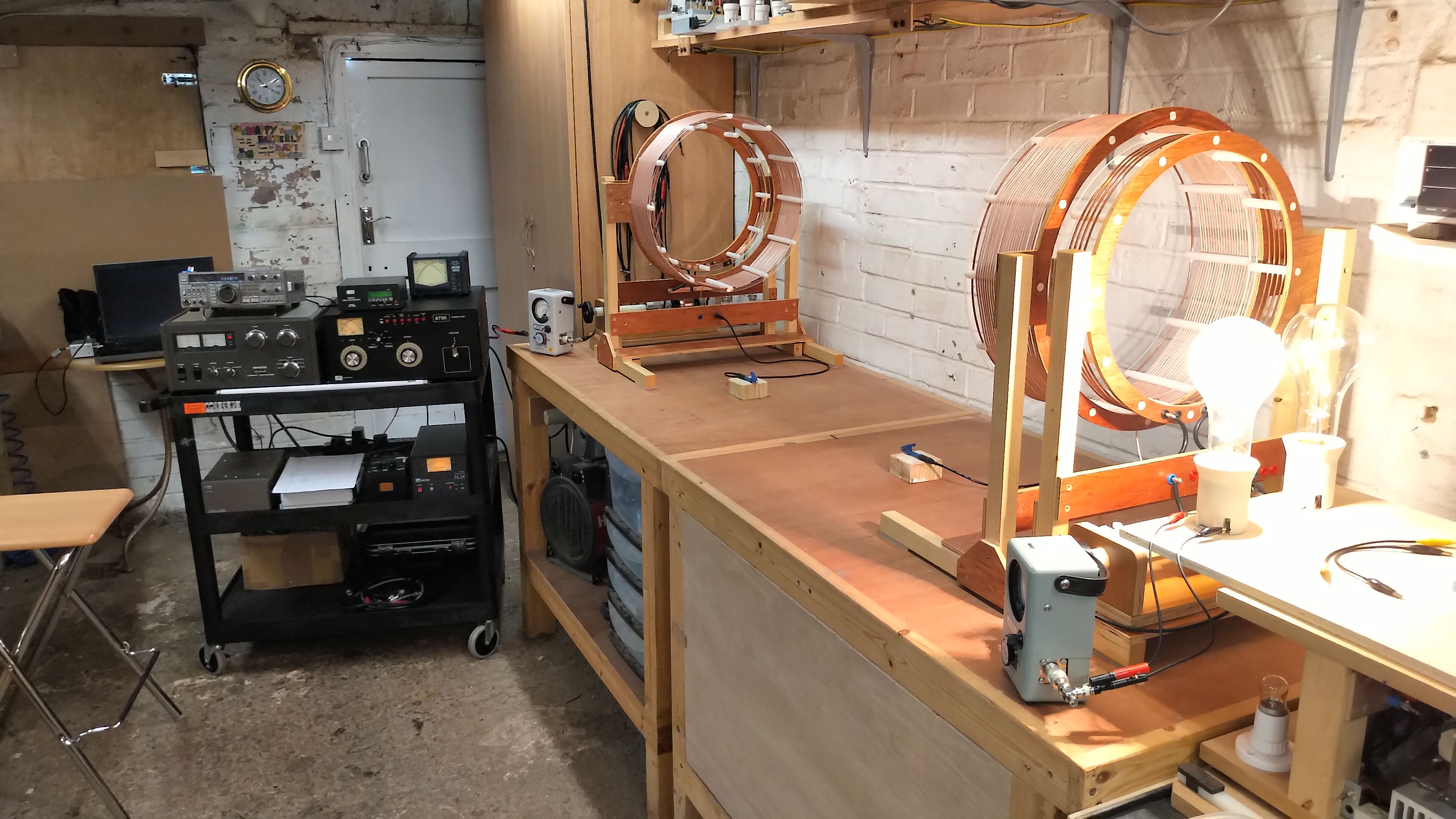
In this post we take a preliminary experimental look at the transference of electric power using a cylindrical coil TC and TMT, energised using a linear amplifier generator, and also the high power transfer efficiency that can be achieved in a properly matched system. The setup, tuning, and matching of the linear amplifier is covered in detail in the video experiment where a 500W incandescent lamp can be fully illuminated at power transfer efficiencies up to 99.9% in the close mid-field region. The power is shown to be transferred to the receiver through a single wire between the transmitter and receiver coil through the longitudinal magneto-dielectric mode, and not through transverse electromagnetic radiation or through direct transformer induction. This high-efficiency, very low-loss transference of electric power is possible as the dielectric and magnetic fields of induction are contained around the single wire.
It is also demonstrated that more than 500W of power can be transferred through a single wire no thicker than a human hair, a 40AWG (0.08mm or 80 microns) nickel plated copper wire, where the power transfer efficiency could be measured up to 100% according to the limits of experimental accuracy of the measurement equipment. Power transfer of this order through such a thin wire is again possible as the dielectric and magnetic fields of induction are contained or guided around the single wire. Removal of the single wire from the receiver end prevents any power transfer to the receiver, which shows that when driven by a linear sinusoidal generator, a lower impedance transmission medium, (in this case the single wire), is needed to guide the induction fields between the transmitter and receiver coils. The experiment presented in this post is the preliminary starting point for a more detailed and extensive study of power transfer efficiency over greater distances in the mid-field region with much longer single wires, and in the far-field with a Telluric transmission medium.
The video experiment demonstrates and includes aspects of the following:
1. Linear amplifier generator setup, matching, tuning, and operation to drive a cylindrical TC and TMT system.
2. Measurement and confirmation of the series and parallel modes of resonance for a balanced TC, against the Z11 impedance results, using the generator exciter and an oscilloscope.
3. Transference of electric power from the generator exciter unit, to a single wire transmission medium incandescent lamp load up to 120W.
4. Transference of electric power from the linear amplifier generator to a 500W incandescent lamp load at the TMT receiver output, and subsequently to two parallel 500W lamp loads.
5. Longitudinal magneto-dielectric (LMD) mode measurement through central null with a fluorescent lamp, and mode interference patterns with an ultraviolet lamp.
6. Transference of electric power efficiency measurements up to 99.9% using an AWG12 single wire between the TX and RX coils.
7. Efficiency measurements up to 100% using an AWG40, 80 micron (0.08mm), 60cm long, single wire between the TX and RX coils.
Video Notes: The maximum calculated power transfer efficiency when using the 12AWG single wire in the video was up to 99.6%. During the introduction the small signal input impedance characteristics Z11, are displayed for a short period in preparation for the subsequent presented linear amplifier setup. These characteristics can also be viewed in Fig. 3.1 below.
Figure 2 below shows the experimental system circuit diagram, followed by an overview of the linear amplifier generator components. Click here to view the high-resolution version.
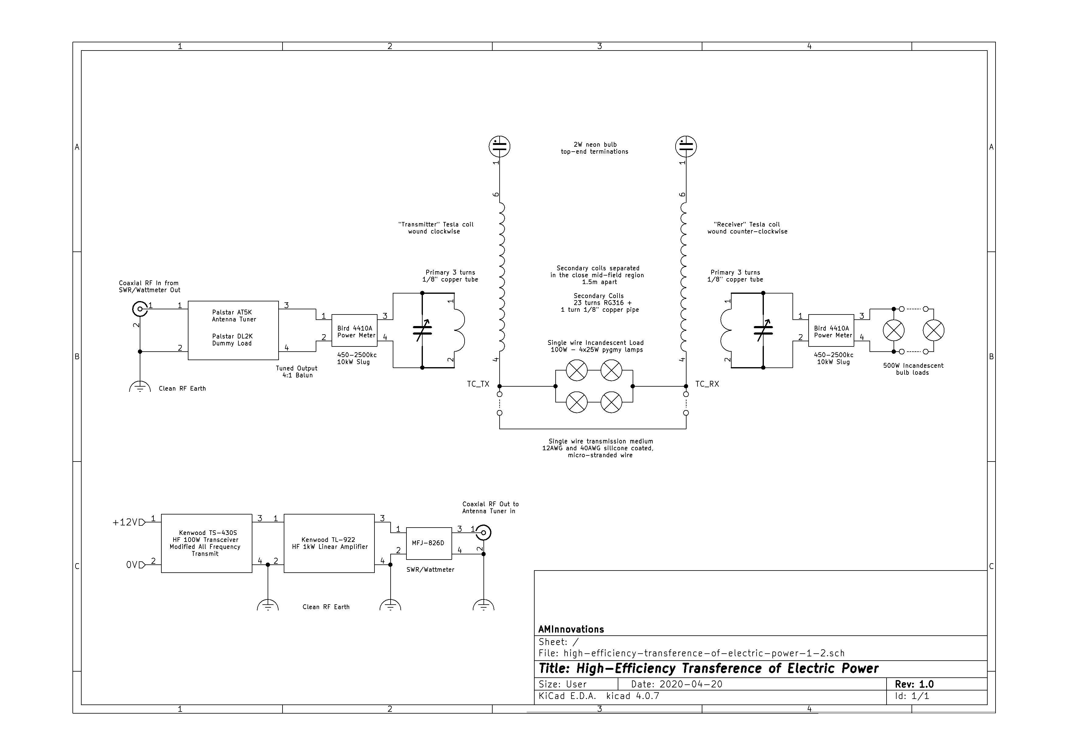

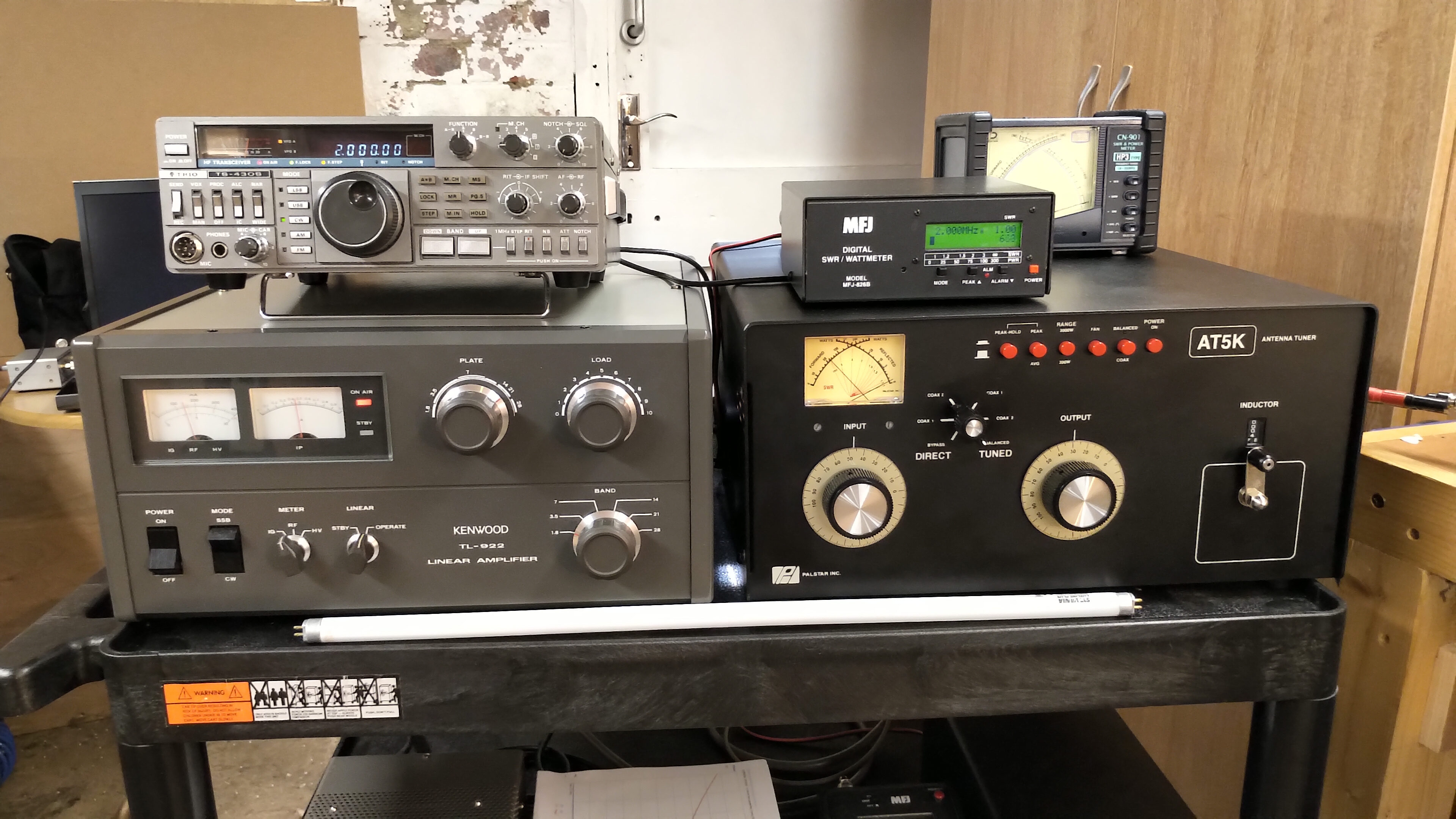
1. The exciter is a Kenwood Trio TS-430S 100W HF amateur radio transceiver. This era of transceiver has digital frequency synthesis, a semiconductor power amplifier, AM and FM modulation, and is easily modified to extend its capabilities. In this case it has been modified to transmit on all frequencies across its tunable range, which makes it into a high-power, up to 120W, bench-top signal generator with modulation capabilities. The transceiver system is not connected to any elevated radiating antennas, and hence will not cause out-of-band interference.
2. The exciter is connected directly to a Kenwood TL-922 1kW linear amplifier which is a vacuum tube based, (dual Eimac 3-500Z), HF power amplifier. This linear amplifier has π-network matching circuits on both input and output. Slightly out of band operation prevents running this linear amplifier at the full 1kW when in the fully matched condition. The output of the linear amplifier is connected through an MFJ-804D digital power and SWR meter to monitor the match at the output of the linear amplifier.
3. The output of the SWR meter is connected to a Palstar AT5K 5kW antenna tuner which handles the impedance transformation from the 50Ω output of the linear amplifier to the ~ 7.5Ω input resistance RS. The AT5K is a T-network matching unit, with input and output continuous variable capacitors, and a continuous variable roller inductor. In balanced output mode a internal 4:1 balun is present at the output of the unit, which further extends the range of possible impedance matching. This unit is capable of tuning a very wide impedance to the 50Ω system impedance, and is required for safe and optimum performance of the linear amplifier when driving TC and TMT systems.
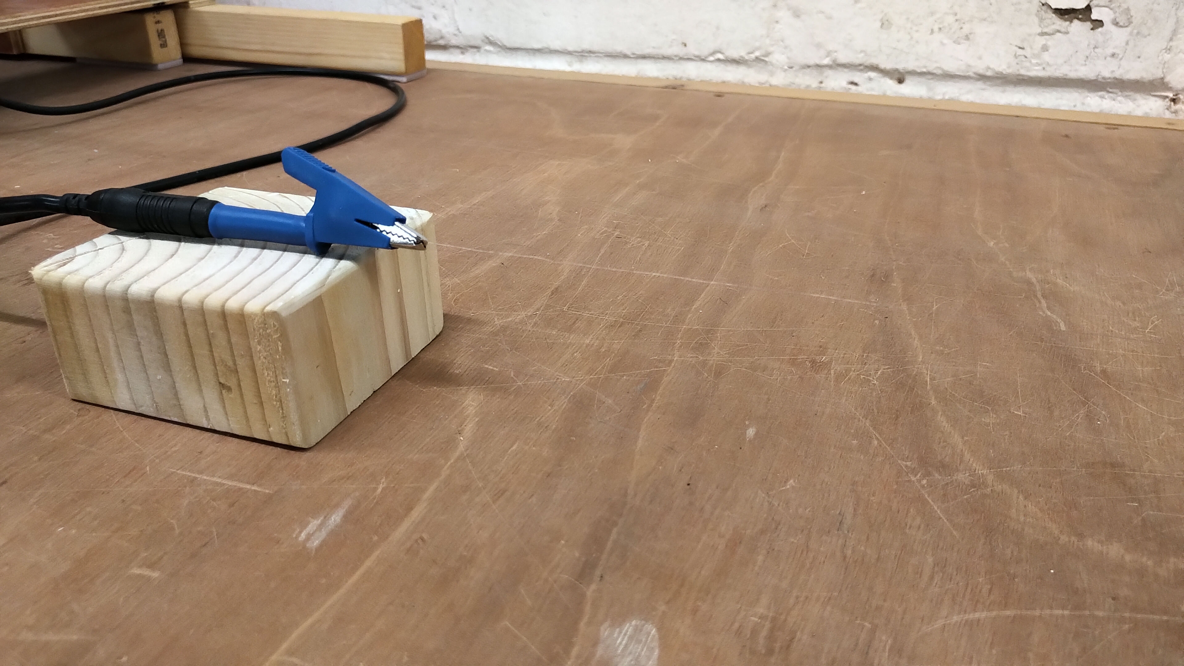
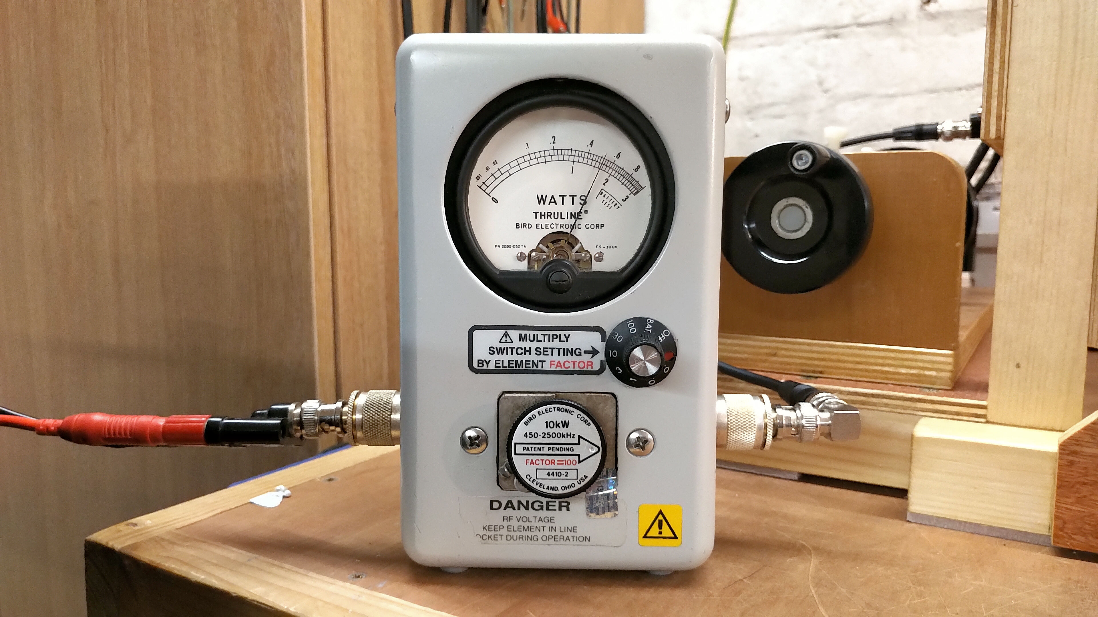
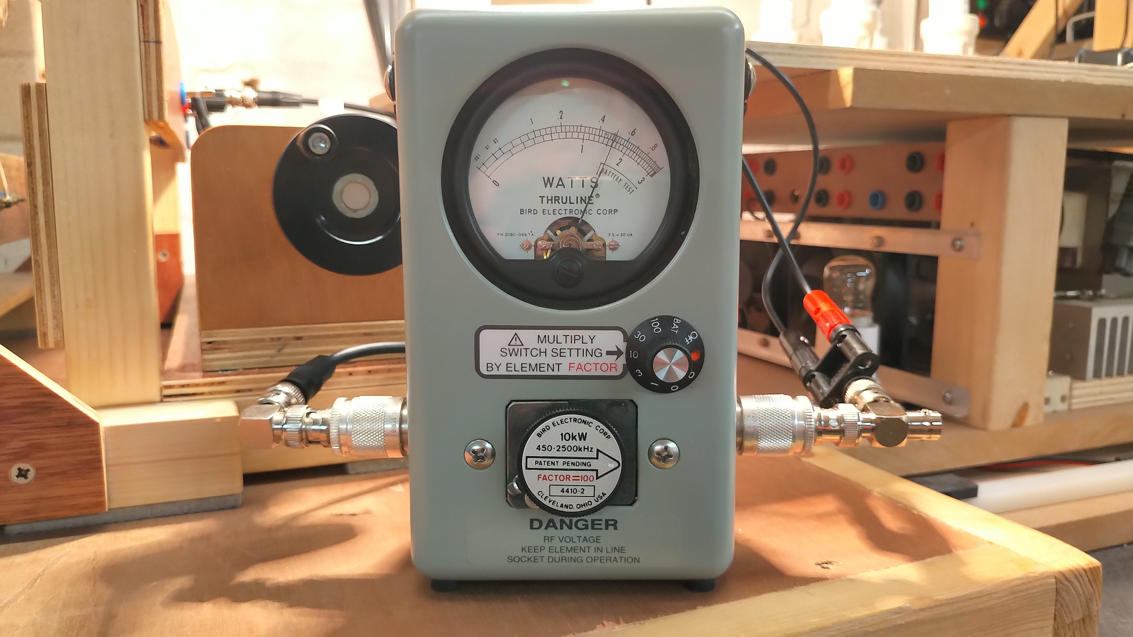
4. The output of the AT5K can be switched to bypass which connects to a Palstar DL2K 2kW 50Ω dummy load which is used to initially tune the output of the linear amplifier for maximum power output at the exciter frequency. When this is completed the AT5K is switched back to balanced tuned output connected to the primary circuit of the transmitter cylindrical coil. Between the output of the AT5K and primary coil is a Bird 4410A Thruline power meter with a 450kc – 2500kc 10kW slug, for measuring the real power actually supplied to the transmitter primary. Between the output of the receiver primary circuit and the 500W incandescent lamp is a second Bird 4410A Thruline power meter with the same rated slug.
In measurements for high-efficiency where the final result is a ratio of the output power to input power, calibration of the key measurement instruments becomes critically important to ensure the highest levels of accuracy and confidence in the measured results. In this case the Bird Thruline power meters at the input and output primary coils were calibrated simultaneously inline with each other, with the actual slugs to be used during the experiment, and on the range that was to be used to make the efficiency measurements. The calibration procedure was as follows:
1. 500W of output power was provided from the linear amplifier generator simultaneously through the two Bird watt meters in series and terminated at the Palstar dummy load. Interconnections were kept to short BNC cables.
2. Both watt meters were first zeroed and then set to scale 10, which for the 10kW 450-2500Kc slug with element factor 100, results in a meter full scale reading of 1000W.
3. With 500W of power provided from the generator to the dummy load both watt meters were adjusted to read the same needle position on the meter scale at 500W. The operation was repeated multiple times with the power being turned-off and reapplied to confirm.
4. The series connection of the meters was then reversed to average out any insertion losses, and step 3 repeated to confirm agreement of the readings, with very slight adjustment to the calibration of each meter for optimal agreement in both steps 3 and 4.
In this way the meters were both calibrated for 500W input power direct comparison on a single range, and with a limit of experimental error of <0.5%. Due to the analogue nature of the meters, readings during the experiment needs to be done carefully and repeatedly in order to minimise errors due to estimation of the needle position when in-between minor graticule marks. It was determined overall that power efficiency measurements can be made by this method within an error limit of ±1%.
Figures 3 below show the key Z11 impedance measurements that relate to different configurations of the experimental apparatus that were used in the video experiment, along with a consideration of their analysis and characteristics relating to the most important phenomena.

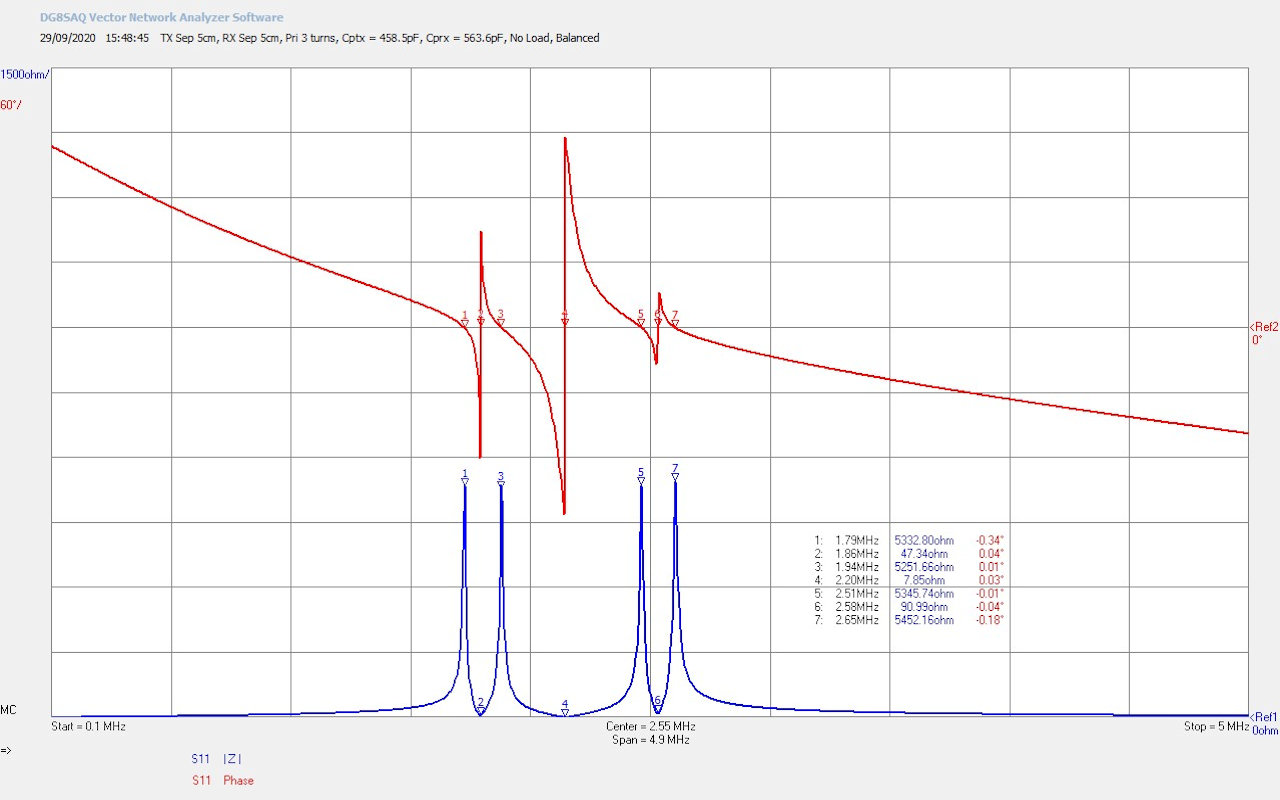


Fig 3.1. Shows the small signal input impedance Z11 for the starting point of the experiment, (also shown on the video), for the transmit cylindrical coil only with a single wire extension that includes a 100W incandescent load. The impedance characteristics consist of the three key points, as explained in detail in the post Cylindrical Coil Input Impedance – TC and TMT Z11. In this experiment the linear amplifier generator was initially tuned to marker M2 the series mode resonance at 2.19Mc. After confirming the Z11 measurements, using an oscilloscope to maximise the voltage output of the secondary, the generator was set at 2.20Mc for the start of the practical experiments. Markers M1 and M3 are the parallel mode resonant points for the transmit Tesla coil, at 1.89Mc and 2.68Mc respectively. In this case the parallel modes have been balanced between the primary and the secondary, in order to maximise coupling through the series mode to the parallel modes, and hence from the generator to the LMD mode in the cavity formed in the secondary coil and single wire extension. The series resonant mode at M2 is suitable for driving the coil using a linear amplifier as the input impedance is minimum, 12.5Ω @ 2.19Mc, which can easily be matched to the power amplifier output impedance of 50Ω, via the Palstar antenna tuner with a 4:1 output balun.
It is interesting to note from the video experiment that the oscilloscope confirmation and measurement of the resonant modes of the Tesla coil is strongly dependent on the matching network used between the generator and the primary of the coil. In the simple case where the exciter was connected to the primary through direct bypass of the antenna tuner, (direct drive), the fundamental series resonant mode could be measured very clearly at 2.14Mc, but the parallel modes could not be identified at all in the measurement. This method is commonly used to measure the Tesla coil series resonant frequency, but completely masks the parallel modes from measurement, leading to an incomplete and ultimately inaccurate characterisation of the properties of a Tesla coil. It should also be noted that the measured maximum voltage peak on the oscilloscope at 2.14Mc does not completely correspond to that measured in the Z11 characteristics of 2.19Mc. In this case where no consideration of input impedance matching has been taken into account the basic oscilloscope measurement yields incomplete and inaccurate measurement results, and whilst gives a close estimate of the best frequency point to drive the Tesla coil, does no yield the optimum frequency and conditions for maximum transference of electric power.
When the same measurement is repeated but with a tuned matching network between the exciter and primary coil, ( in this case the balanced and tuned T-network in the Palstar), the oscilloscope measurement closely matches the Z11 characteristics. Both parallel modes and the series mode can be measured accurately at the correct frequencies, and the initial starting point was again set to 2.20Mc. The difference in the two measurements is a clear example of why it is important to carefully match the output impedance of the generator to the input impedance of the Tesla coil, and this is even before we consider the optimum and maximum transfer of electric power. To maximise power transfer and obtain the highest efficiencies it is crucial to minimise power reflected from the primary circuit to the generator.
Fig 3.2. Here the transmitter and receiver coils are coupled together with a single-wire transmission medium to form a TMT system. No load is placed in the single wire, and no load is attached to the output of the receiver primary. This represents the highest quality factor, unloaded, characteristics of the system, and combines four parallel modes (M1, M3, M5, and M7), and three series modes (M2, M4, M6) together. The TMT system has been carefully balanced using the primary tuning capacitor in the both the transmitter and receiver to match the impedance of the parallel modes across the system. Balancing of the parallel modes in this way appears to contribute significantly to maximising the LMD mode in the cavity through coupling maximum power between the TEM and LMD modes between the primary and secondary coils in both the transmitter and receiver. A more detailed analysis of this TMT system has already been presented in post Cylindrical Coil Input Impedance – TC and TMT Z11 – Fig. 2.1.
It should be noted that the fundamental series resonant mode at M4 has remained constant at 2.20Mc, and for the type of linear amplifier generator being using in this experiment, is the best frequency point to drive the TMT system. At M4 the input impedance is at its minimum and is purely resistive at 7.85Ω, and is well within the matching range of the Palstar antenna tuner with a 4:1 balun at the output. Tuning to drive at M4 is also the most stable part of the Z11 characteristics, which is most determined by the the reciprocal wire lengths of the secondary coils. It is possible to also drive the TMT system using this generator at series mode points M2 and M6. Whilst this will preferentially couple energy into different aspects of the parallel longitudinal modes, the characteristics of these points in impedance are highly dependent on the primary tuning of both coils, and the loading conditions in any part of the TMT system, in the single-wire, at the output of the receiver primary, or even in proximity to other lower impedance structures. Driving the system at unstable positions M2 and M6 would require a lot of continuous tuning adjustments, and inevitably having to run at a higher SWR during experimental operation. For experiments across the characteristics of the parallel modes it is recommended to use a series feedback oscillator which is covered in detail in the second section of post Cylindrical Coil Input Impedance – TC and TMT Z11.
Fig 3.3. Here the TMT system of the previous figure has had a 100W incandescent lamp load added in the single-wire cavity between the transmitter and receiver. The characteristics remain essentially very similar, although the Q of the system is reduced significantly by the resistive component in the cavity. The fundamental series resonant mode at M4 has only shifted down in frequency by ~10kc to 2.19Mc, however the input impedance of the system has now increased to 19.1Ω based on the transformed down additional resistance of the 100W load in the secondary cavity. The tuning of the primary capacitors has been adjusted to maintain a balanced condition between the parallel modes. The biggest impact of adding a load in the cavity is to damp-down the parallel modes, and hence reduce the purity of the LMD mode formed in the cavity of the TMT system.
For clarity, the cavity extends between the top-end of the transmitter secondary, through the single wire transmission medium and load, and up to the top-end of the receiver cavity. Power is transferred from the generator through the primary circuit, and to the secondary primarily in the series TEM mode, which is further coupled to the parallel modes in the both the primary and secondary coils, and hence into the LMD mode across the cavity. Power is coupled out at the receiver through the reverse process from the LMD mode to the receiver parallel modes, and into the series TEM mode in the primary circuit. It is a condition of an LMD coupled TMT system that the frequency of the LMD mode < TEM mode. The LMD mode can be maximised by maximising the parallel modes in the coils which includes:
1. Specific and careful arrangement of the coil geometry (e.g. a balanced cylindrical coil), windings number, ratio and spacing, and coil materials.
2. Tuning of the parallel modes to balance the characteristics between the primary and secondary coils in both the transmitter and receiver.
3. Impedance transformations, characteristics, and loading within the single-wire transmission medium.
Coil geometry and their characteristics for Tesla coils and TMT systems are covered in detail in post Tesla Coil Geometry and Cylindrical Coil Design.
Fig 3.4. Shows the effect of moving the 100W lamp load from the single-wire to the output of the primary circuit of the receiver. The Q of the system remains reduced, and the parallel modes of the receiver coil have been almost completely damped-down (suppressed), so that they merge into the parallel modes of the transmitter, and appearing as only two parallel modes at M1 and M3. With slight transmitter primary capacitor tuning the merged parallel modes of the receiver can be revealed as slight distortions to the peak shapes at M1 and M3. The fundamental series resonant mode at M2 remains constant at 2.20Mc as the wire length in the secondary coils of the TMT system cavity has not changed, but the input resistance has risen significantly to 59.8Ω, as the resistive load of the incandescent lamps is transformed across the TMT system from receiver back to transmitter input. In this case the 59.8Ω input resistance at M2 is closer to the system impedance of 50Ω of the linear amplifier generator.
It should be noted that this represents another way to match the system impedance of the generator to the input of the TMT system, by arranging a suitable resistance load at the output of the receiver. The impedance transformation across the complex transmission line of the TMT apparatus, ensures a good TEM match at the input to the primary. The disadvantage of tuning in this way is that the resistive load reduces the Q of the system, and damps-down the parallel modes of the coils, which ultimately reduces the efficiency of the TMT system for the transference of electric power.
Fig 3.5. Shows the dramatic effect of connecting a 500W incandescent lamp at the output of the receiver, which has significantly unbalanced the TMT cavity, and suppressed the free-resonant characteristics of the receiver, through the low resistance and inductive impedance of the 500W lamp. The large collapse of the receiver characteristics has shifted the transmitter parallel modes M1 and M5 closer together, the lower parallel mode of the receiver at M3 is still present but very small, and the upper parallel mode of the receiver (from the receiver primary coil) is no-longer present. The fundamental series resonant modes are shifted as well, with the transmitter moving down to 2.02Mc, and the receiver moving up to 2.30Mc. The best driving point for the generator is now at M2 at 2.02Mc and with a input resistance of 24.7Ω, which is easily transformed and matched by adjustment of the antenna tuner. M4 the series mode for the receiver could also be used as the driven point, although it is likely that less power will be coupled through the parallel modes at this point and hence into the LMD mode, due to the collapse of these modes from the high loading on the receiver coil.
It should be noted here that despite the imbalance of the impedance characteristics, very high-efficiency power transfer between the generator and the load can still be accomplished through the coupling between TEM and LMD modes in the secondary coils, and through the strong LMD mode maintained in the low impedance cavity of the single-wire transmission medium. In this arrangement with a large, low impedance load at the receiver transference of electric power efficiencies have been measured up to 99.9% in hair-line thickness (0.08mm) single-wire cavities.
Figures 4 below show highlights from the video experiment, and also greater clarity on some of the key power measurements taken during the experiment, including high-efficiency power transfer results at > 99%.
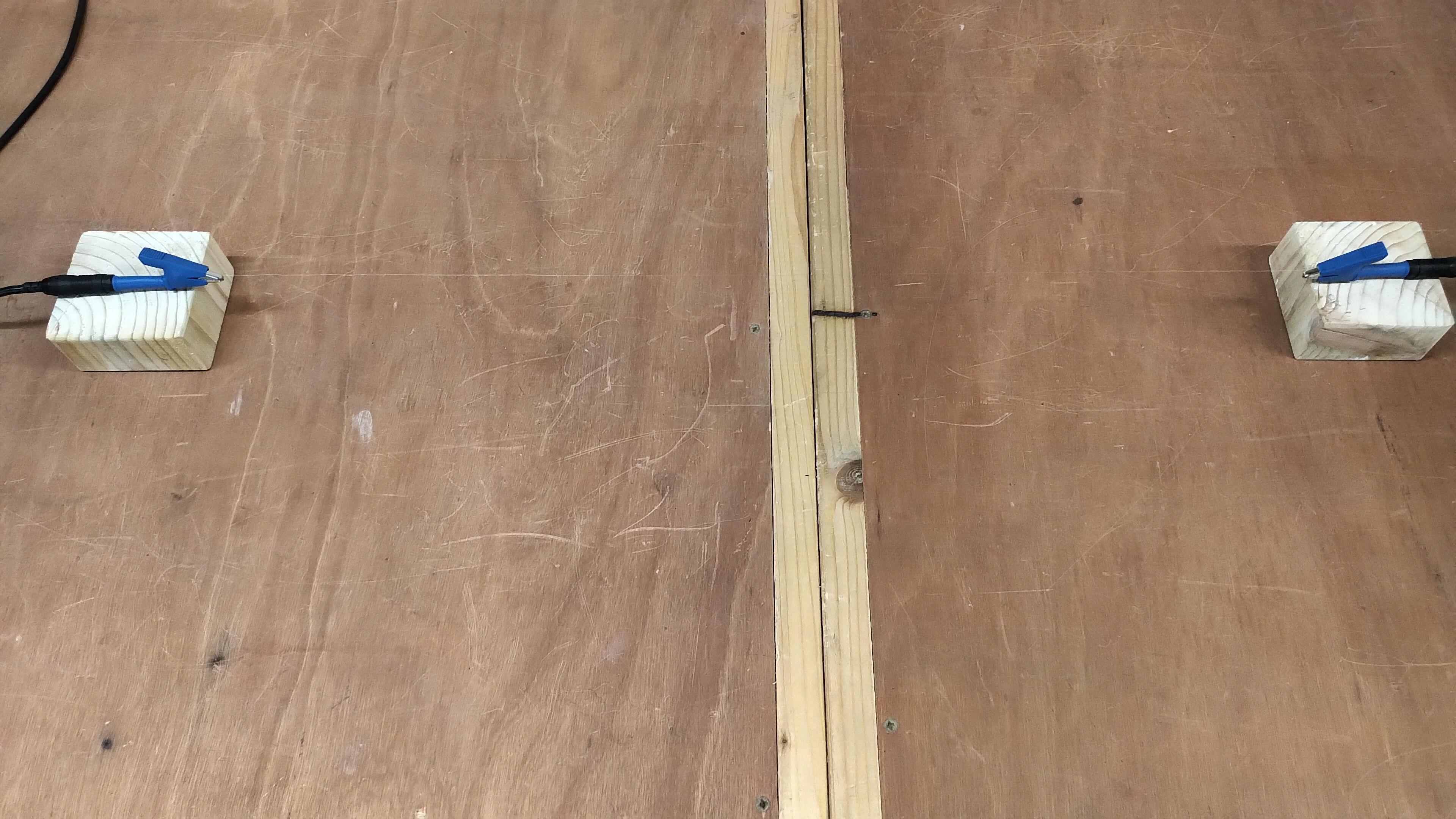


The experiments show the seemingly amazing result of transferring stably 500W of power at very high-efficiency, (peak 800W measured in the experiment, but with lower efficiency), via a single wire 60cm long and 0.08mm thick (40AWG), and comparable to the thickness of a human hair. In a standard electric circuit we would expect to transfer this magnitude of power between the generator and the load using a suitably rated twin-wire arrangement. In the TEM mode the dielectric and magnetic fields of induction establish an alternating potential across the load and an alternating current flowing through the load. As the impedance of the incandescent load is dominated by the resistive part, almost all of the power is dissipated in the lamp element as heat and light, and with resistive and inductive losses in the circuit cabling and connections.
This is in fact what occurs in the receiver primary circuit which is a conventional twin-wire circuit. The receiver Tesla coil acts a step-down transformer and energy is coupled from the secondary coil resonant modes, (both series and parallel), to the primary coil. The dielectric and magnetic fields of induction coupled through to the primary establish in a TEM mode and hence setup alternating potential across the load and an alternating current flowing through the load. The power in the primary receiver circuit can be measured accurately using a standard RF power meter, (such as the Bird 4410A used here), in a standard twin-wire circuit.
There is an equivalent and reciprocal process in the generator primary circuit. The linear amplifier supplies RF power through a standard power meter into the twin-wire primary circuit at the transmitter. The dielectric and magnetic fields of induction established by the generator in the TEM mode, setup an alternating potential across the primary coil and an alternating current flowing through the primary coil. Power is coupled to the secondary coil through the series and parallel resonant modes of the transmitter Tesla coil. Power efficiency can be measured accurately in this system because the transmitter and receiver power measurements both take place in standard twin-wire circuits that are equivalent in impedance using standard twin-wire RF power meters. The primary circuits of both the transmitter and receiver are suitably arranged to minimise resistive and parasitic inductive losses, using good RF connections and cables.
In the cavity established between the transmitter and receiver secondary coils and through the single-wire transmission medium it is conjectured that very high-efficiency transference of electric power through a 60cm 40AWG 0.08mm single wire is possible due to the LMD mode being established across the cavity, where the dielectric and magnetic fields of induction form a longitudinal wavefront that traverses the cavity establishing a standing wave with central null point, and a varying (travelling) voltage and current phase relationship along the cavity. This varying voltage and current relationship in the single-wire cavity can be visualised using the ultraviolet lamp used in the experiment where a travelling interference pattern is setup in the lamp. This interference pattern results from the longitudinal wavefront traversing backwards and forwards between the two secondary top-loads guided by the single wire in-between. In this way the longitudinal cavity extends from the top-load of the transmitter secondary through to the base, into the single-wire, and into the base of the receiver secondary up to the top-load.
When the tuning of the cavity is adjusted through the parallel modes the interference pattern can be made stationary as demonstrated in the video, and represents the optimal tuning position for the LMD mode in the cavity, it is also the point where power transfer efficiency is highest, and most power can be transferred through the cavity between the transmitter and receiver. This is also the point where a diffuse fluorescent lamp will show a null point in the electrical centre point of the cavity. Either side of this tuning the interference pattern will be seen to move towards the receiver and transmitter eventually starting to collapse towards either end of the single wire medium as the LMD mode collapses in the cavity. Coupling to the LMD mode in the secondary coil is dependent on the parallel modes in the coil and these can be adjusted very accurately using the primary tuning capacitors in the transmitter and receiver primary circuits. The LMD mode appears optimised and maximum when the primary and secondary parallel modes are balanced using the primary tuning capacitors, as shown in figures 3.
In summary, it is conjectured here that very high-efficiency transference of electric power is directly possible because of the LMD mode established in a single wire cavity, where the dielectric and magnetic fields of induction are guided around the low impedance single-wire conductor. The single-wire acts in this case like it were a monopole waveguide which would only be possible where the LM and LD modes are spatially in phase, but temporally out of phase, the condition that I conjecture is necessary for the LMD mode to form in the cavity. Real power can be transferred and dissipated at the receiver load via the single-wire transmission medium, because both the dielectric and magnetic fields of induction are guided across the cavity, and where both of these induction fields are necessary to transfer power over the cavity distance. It does not appear possible that transference of electric power can occur here through dielectric field induction alone between the transmitter and receiver coil, but rather that both the magnetic and dielectric induction fields extend across the system by virtue of LMD wavefront in the cavity, and indeed if the single-wire is disconnected from either end (guiding cavity terminated), then no power can be transferred from source to load.
All this said, it now makes sense and can be understood how 500W of power can be transferred from source to load in a TMT system where part of the cavity is a single-wire conductor the thickness of a human air. This ultra-thin section is still only a part of the guiding conductor in the cavity, and appears as yet an even more effective guide to the dielectric and magnetic fields of induction in the configuration of the LMD mode. It is conjectured here from the experiments and measurements so far, that the efficiency of transference of electric power in an LMD transmission system appears to increase as the single-wire transmission medium is reduced in conductor volume per unit length, to the boundary condition limit of the skin depth for the material, in this case ~ 0.046mm (46µm) in copper at 2Mc, where the efficiency would reach a maximum before falling-off again.
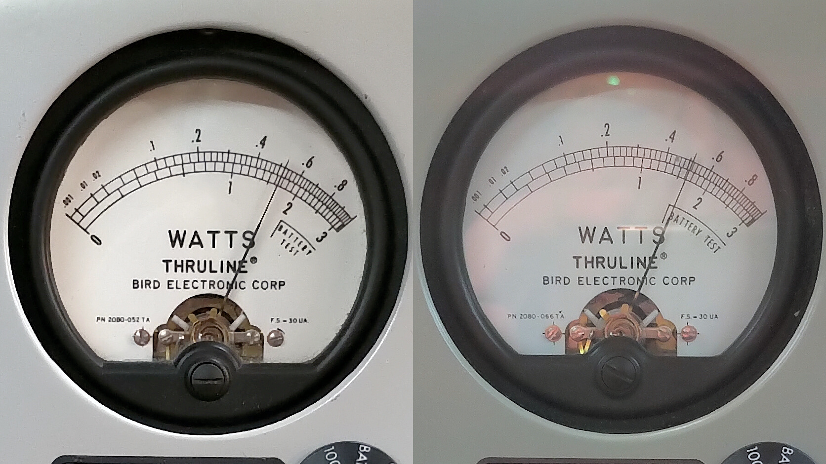
Fig. 4.6. shows the comparison of the transmitter and receiver power measured during sustained transference of 500W of power between the source and load, where the wattmeter gauges have been combined from Figs. 4.4 and 4.5 into a single image. The transmitter meter on the left shows 520W of power, and the receiver on the right 515W of power. The calculated transference of electric power efficiency in this case is > 99% ±0.1%, and could be measured consistently during the period of operation. Other measurements of power transfer efficiency were taken at various positions and states of tune in the video experiment and consistently in the range 95% – 100%. 100% power efficiency was measured initially when using the 0.08mm single-wire conductor but dropped to a constant 99.9% after further tuning adjustments.
Summary of the results and conclusions so far
In this post we have experimentally observed high-efficiency transference of electric power sustained at over 99%, and maximum 100%, with a estimated error of ±0.1%. The experiments were conducted in the close mid-field region in a TMT system driven with a linear amplifier generator, and using high power incandescent lamp loads in the receiver primary circuit. From the experimental results and measurements presented the following observations, considerations and conjectures are made:
1. The high-efficiency transference of electric power across a 0.08mm single-wire transmission medium is possible because of the Longitudinal magneto-dielectric (LMD) mode established in the cavity between the transmitter and receiver secondary coils.
2. The transfer of power in the LMD mode across the cavity results in the dielectric and magnetic induction fields being guided around the single-wire like a monopole waveguide. Power does not appear to be coupled from transmitter to receiver by dielectric induction alone.
3. The LM and LD modes are spatially coherent (in-phase) and temporally out-of-phase, combining to form the LMD mode that belongs to longitudinal transference phenomena.
4. The LMD mode shows voltages and currents that can be measured along the wire with changing phase relationship, and is considered in more detail in Transferece of Electric Power – Part 1.
5. The LMD mode forms as a standing wave in the cavity with a null point at the centre of the reciprocal cavity which can be observed using a fluorescent lamp.
6. The LMD mode can be observed through the interference pattern generated in a ultraviolet lamp placed close to the single wire cavity, from the longitudinal wavefront traversing backward and forward across the cavity. Tuning of the cavity using the parallel resonant modes in the transmitter and receiver varies the direction of interference, and is stationary at the optimum point.
7. The efficiency of transference of electric power in an LMD transmission system appears to increase as the single-wire transmission medium is reduced in conductor volume per unit length, to the boundary condition limit of the skin depth for the material.
8. The optimal efficiency transference of electric power requires optimal matching of the generator to the transmitter coil at the fundamental series resonant mode in order to transfer as much power as possible into the secondary cavity, correct tuning of the LMD mode through coil geometry and parallel mode tuning, and optimal matching between the receiver coil and the load to extract the maximum power.
This post has explored aspects of the TEM and LMD modes in the high-efficiency transference of electric power, including generator matching, tuning, and observation and measurement of various phenomena associated with TMT operation using a linear amplifier generator. The experiments conducted here are in the close mid-field region and form an encouraging starting point to extend the distance between the transmitter and receiver. Further work in progress, and to be subsequently reported, includes transference of electric power using longer single-wires where the transmitter and receiver are placed in different rooms, and buildings, and comparison over the same distance with ground connected transmission, and full Telluric transmission for far-field experiments.
Click here to continue to the next part, looking at High-Efficiency Transference of Electric Power – 11m Single Wire.
1. A & P Electronic Media, AMInnovations by Adrian Marsh, 2019, EMediaPress