


In this second part on high efficiency transference of electric power, we take a look at the characteristics and power efficiency of a cylindrical coil TMT system where the transmitter and receiver coils are spaced further apart in the mid-field region. In this experiment a single wire transmission medium 11m long is used to separate the coils into different rooms at the laboratory, and a remote camera is used to observe the power at the receiver load measured by an RF wattmeter. Transference of electric power over 11m, and the characteristics of a TMT system coupled by the LMD mode at this distance, is shown to be remarkably different from the close mid-field region, and requires a very different setup and configuration of the experimental apparatus in order to optimise the efficiency of power transfer up to 96%.
In the close mid-field region with a 2m single-wire in the previous experiment on High-Efficiency Transference of Electric Power, the maximum transfer efficiency was achieved when the TMT system was configured, tuned, and operated at the point where the parallel modes were balanced, and the generator was optimally impedance matched to the system. It was conjectured that this balance contributes to maximising the power transferred from the generator to the twin-wire primary circuit TEM mode, to the single-wire LMD mode within the cavity formed between the transmitter and receiver secondary coils, and back to the twin-wire primary circuit TEM mode to the load.
In the mid-field region with an 11m single-wire we will see that this balanced mode setup leads to a maximum efficiency of ~40%. It is demonstrated that it is necessary to significantly mismatch the balance between the transmitter and receiver coils in order to get the LMD mode to extend across the single-wire transmission medium and restore transfer efficiency to over 90%. Transmitter and receiver primary circuit mismatch is mainly used to restore the transfer efficiency, along with fine adjustment through generator to TMT system TEM mismatch, measured at a range of Standing Wave Ratio (SWR) of 1, π/2, φ (the golden ratio), and 2.
The video experiment demonstrates and includes aspects of the following:
1. Small signal ac input impedance Z11 for a cylindrical coil TMT system in the mid-field region, and connected via an 11m 12AWG single wire transmission medium.
2. Z11 balanced parallel mode impedance measurements, for a reciprocal TMT configuration with 3 primary turns and matched primary capacitor tuning.
3. Z11 unbalanced parallel mode impedance measurements, for a non-reciprocal TMT configuration with 4 transmitter primary turns, 2 receiver primary turns, and mismatched capacitor tuning.
4. Transference of electric power from the linear amplifier generator to a 500W incandescent lamp load at the TMT receiver output via the reciprocal TMT configuration, and with a measured efficiency around 40%.
5. Transference of electric power to a 500W incandescent lamp load at the TMT receiver output via the non-reciprocal TMT configuration, and with a measured efficiency of up to 96%.
6. Demonstration of the high tension and associated discharge that can be drawn from the high-end of the receiver secondary coil, via the 11m single wire.
7. Transference of electric power efficiency measurements up to 96% (90% average) at 400W dissipated load power (peak 500W), in the 160m amateur radio band at 2.01Mc, and via an AWG12 single wire 11m long between the TX and RX coils.
Video Notes: The receiver power meter reading is shown on the inset video in the top right corner. For clear viewing and reading of the inset meter readings, and the VNWA software measurements, “720p” or “1080p” video quality is recommended, and may need to be selected manually from the settings icon once playback has started.
The experimental system circuit diagram, followed by an overview of the linear amplifier generator components is available here.
Figures 1 below show the key small signal input impedance characteristics Z11 presented in the video experiment, along with a more detailed analysis as to their impact on the observed and measured experimental results.
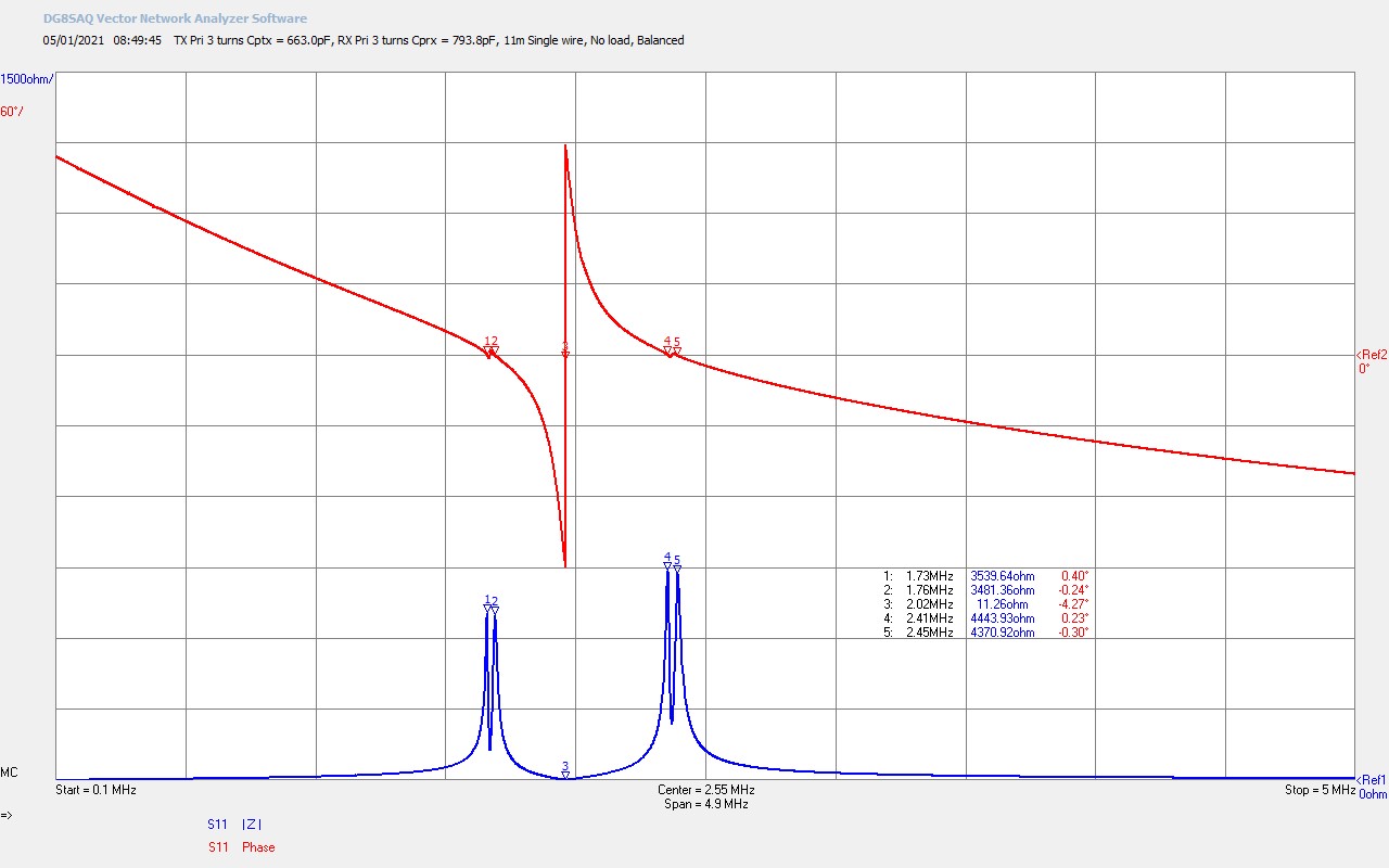

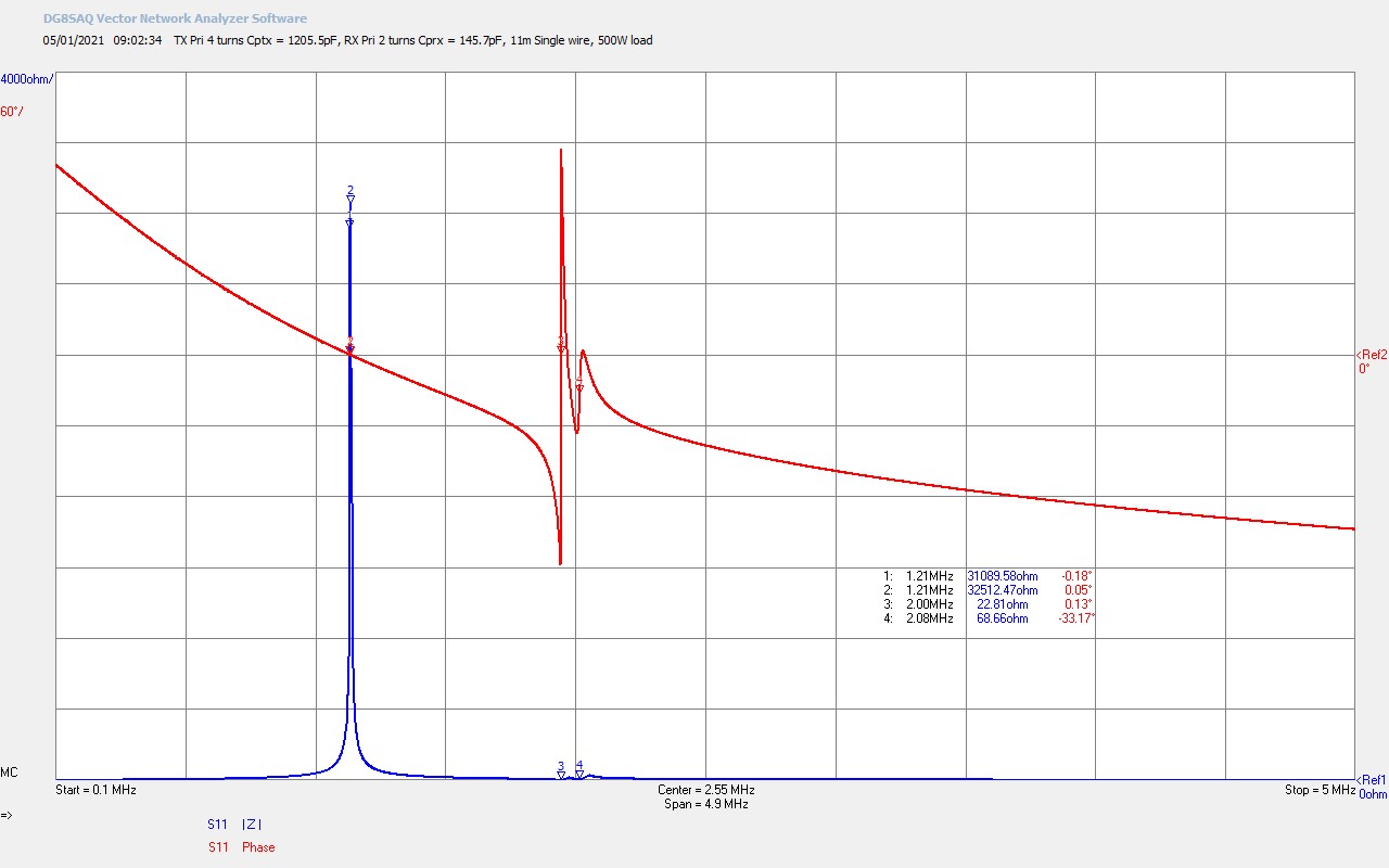


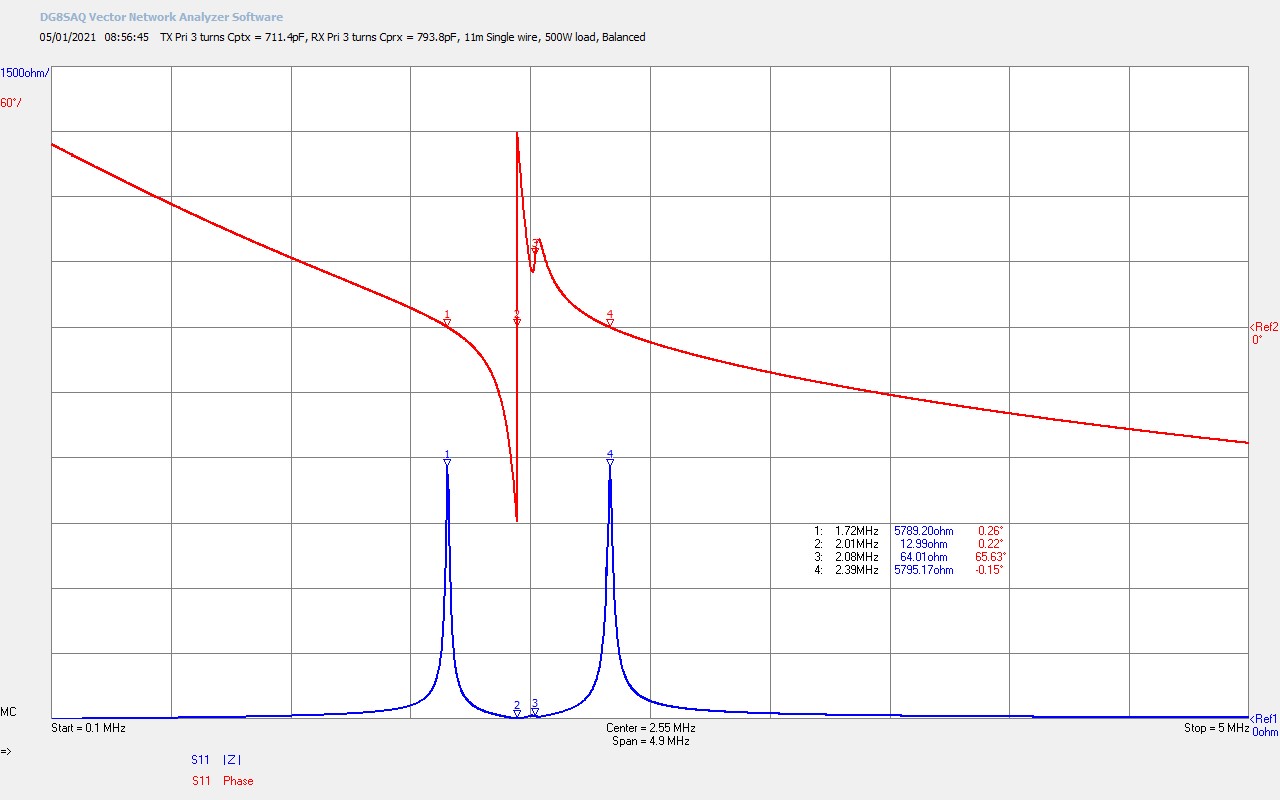

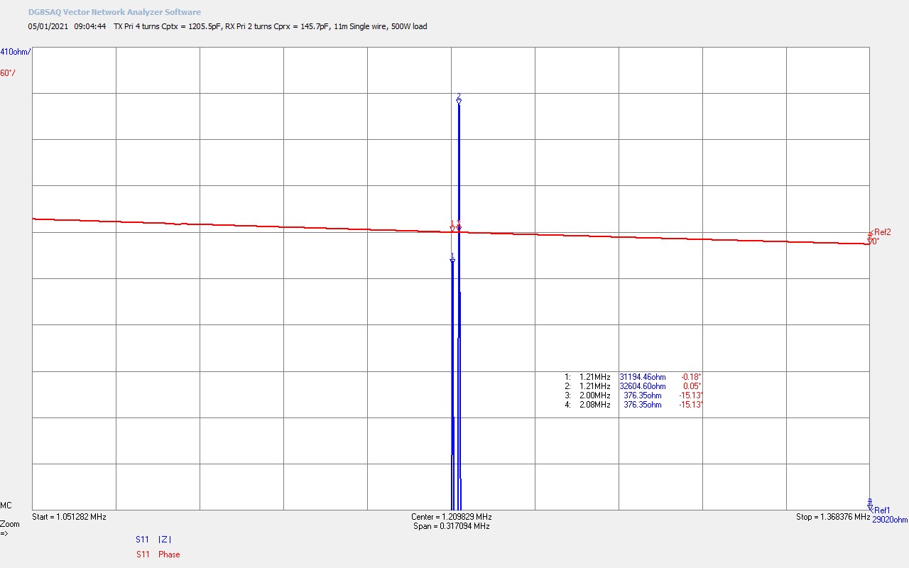
Fig 1.1. Shows the balanced and reciprocal input impedance for the cylindrical TMT system with 11m single wire transmission medium. The parallel modes, at markers M1, M2, M4, and M5, are balanced in the normal way by adjusting the primary tuning capacitors at both the transmitter and the receiver. The fundamental series resonant frequency M3 @ 2.02Mc has a series resistance RS = 11.3Ω, and is the primary drive point for the linear amplifier generator used in the experiment, with fine tuning around this point established at 2.01Mc as the optimum point. The parallel modes, one from the primary and one from the secondary, for both the transmitter and receiver coils are balanced, and show the frequency splitting that occurs when resonant modes of a very similar frequency are coupled together.
This form of impedance characteristic has been very well covered before in many posts on the website, and is discussed in detail in Cylindrical Coil Input Impedance – TC and TMT Z11. Previously these characteristics have been studied in the close mid-field region, typically with a single wire in the region of 1.5-2m long, or at least 2-3 times the diameter of the secondary coil, (0.5m in the case of the cylindrical TC). In this region the coupling between the transmitter and receiver coils, via the single wire transmission medium has been shown to be significant and the parallel modes split up to 200kc apart in frequency, as can be seen here. Within the split parallel regions there is a well defined and distinctive phase change from the extended series mode. The extended series modes, both upper and lower, can also be used as drive points for a linear amplifier generator, although the series resistance at these points is higher than the fundamental series mode, and ultimately will couple less total power from the generator through the TMT system.
With the single wire now extended to 11m in the mid-field region it can be clearly seen in this impedance scan that the coupling between the parallel modes of the transmitter and receiver has reduced, the frequency split is less at 30kc, and the extended series mode phase change is only just defined between markers M1-M2 and M4-M5. The fundamental series mode remains dominant at M3 and is the optimum drive point for linear amplifier generator. Overall the transmitter and receiver coils are coupled together by the single wire transmission medium in the TEM mode, but the coupling is reduced from the close mid-field region, and the additional impedance of the longer single wire is transformed back through into the transmitter primary and reflected in the increased series mode resistance at M3, RS = 11.3Ω.
Fig 1.2. Shows the effect of adding a 500W incandescent lamp load at the receiver primary coil output. The transmitter primary tuning capacitor CPTX has been adjusted from 663pF to 711pF in order to balance the transmitter parallel modes. The receiver primary tuning capacitor CPRX remains the same at 793pF. The resistive and inductive loading presented by the high-power incandescent lamp at the receiver has significantly changed the operating characteristics of the TMT system from a well balanced cavity, to a strongly unbalanced cavity, at least in terms of the TEM input impedance Z11.
The parallel modes of the receiver coil have been almost entirely suppressed with only a very slight presence at M3, and the overall resonant circuit properties of the receiver distorted and skewed away from the reciprocal coil characteristics of the unloaded receiver TC, to the characteristic shown at M3. It is important to note that this huge imbalance in the receiver end of the cavity in both the TEM mode, and I would conjecture the LMD mode due to the definite and distinctive change in the parallel modes, leads to a setup in this experiment where the transmitter end also needs to be unbalanced in order to reestablish the maximum efficiency in the transference of electric power. It is conjectured and discussed later that the setup change to the transmitter establishes a balance again in the LMD mode in the cavity when the total effect of the receiver and the longer single wire are taken into account together.
The fundamental series resonant mode has shifted down very slightly to 2.01Mc, RS = 13Ω, which was found to be the optimum drive point for the linear amplifier generator during the tuning and setup part of the experiment prior to the video experiment itself. The balanced reciprocal setup shown in figures 1.1 on this page, and 2.1 here , which was so effective in the close mid-field region, is shown to yield a maximum power transfer efficiency of now more than 35-45%. It is clear that the coupling introduced by the single-wire transmission medium and the impedance that this presents to both the TEM and LMD mode is critically important in both the setup and operation of a TMT system over distance.
Fig 1.3. Here the setup of the transmitter and receiver has been changed from that of the balanced reciprocal cavity condition, which yields power transfer efficiencies no higher than 35-45%, to the seemingly mismatched characteristic that yields measured transfer efficiencies up to 96% in the experiment. This setup requires the transmitter primary turns to be increased from 3 to 4, and a significant increase in the primary tuning capacitor CPTX = 1206pF. In correspondence, the setup of the receiver primary turns is also decreased from 3 to 2, and the primary tuning capacitor is significantly reduced to CPRX = 146pF. In this setup the input impedance Z11 for the TEM mode appears highly imbalanced, however for the LMD mode it is conjectured that a strong coupling and balance is re-established.
The fundamental series resonance at M3 has again only shifted very slightly in frequency to 2.0Mc, as the wire length of the experiment, the biggest contributor to this mode, remains constant, and with an increased series resistance RS = 22.8Ω. This still represents the best generator drive point for this experiment, with the lowest series resistance, and maximum coupling to the both the series and parallel modes that are active in this configuration. Transmitter parallel modes at M1, M2, and heavily suppressed around M3 and M4, are shifted quite considerably by the primary tuning capacitor mismatch. The dominant parallel modes, and hence conjectured to contribute most strongly to the LMD mode in the cavity, are now at M1 and M2 and involve both the transmitter and receiver, which will become apparent in the next figure. It should be noted that this figure is on a vertical magnitude of impedance scale of 4kΩ, whereas the previous figures where set to 1.5kΩ. This emphasises the very strong lower parallel modes and suggests that the transmitter pump action, from the generator to the LMD mode in the cavity, has been preferentially increased at this lower frequency of 1.2Mc.
The reduction in the primary setup at the receiver appears to have loosened the coupling between the primary and secondary coils of the receiver, which in turn has increased the Q of the free resonance in the secondary coil, increasing the phase change at M3, and emphasising the receiver characteristics transformed across the single wire cavity back to the transmitter. In short it appears like the LMD pump action into the cavity has been increased, whilst the Q of the receiver has also been increased. It is conjectured here that this combination of effects re-establish a balanced condition for the LMD mode, and hence a low impedance path for this mode across the cavity. With the LMD mode established across the cavity the efficiency of power transfer is pushed right back up to 95+%. Losses in the TEM mode are clearly increased with the longer single wire, but it is conjectured this is not the case for the LMD mode which is coherent spatially but not temporally over the entire cavity.
The split in frequency between the fundamental series mode at M3 and the upper extended series mode at M4 is now only 80kc, which is a very different condition than that which occurs in the balanced non-loaded mode. This close correspondence between these series two modes at the transmitter and receiver suggests part of the mechanism that allows very high-efficiency transference of electric power, where power is coupled from the primary to the secondary and hence into series modes to parallel modes, and then back through parallel modes to series modes at the receiver, a transformation across the TMT system from TEM to LMD and back to TEM mode in the load. Ultimately real power is passed from the generator through to the load which requires the TEM mode in both primary circuits, and the LMD mode as a result of the combined LM and LD modes across the cavity of the TMT.
Fig 1.4. Here we see a zoom of the peak of the dominant parallel mode from the previous figure at M1 and M2. Very interestingly we see that this peak is actually split into two peaks, suggesting two parallel modes that are dominant in both the transmitter and receiver but very weakly coupled. This now sets up the condition that we have two parallel modes separated by only ~ 1kc, and two series modes separated by only 80kc, from both the transmitter and receiver. I conjecture that it is this combination of series and parallel modes at each end of the TMT that makes it possible to yield very high-efficiency transference of electric power in this TMT system with a longer single-wire.
So what appears to be a loaded and unbalanced setup actually yields a TMT system that is balanced and matched for both the TEM and LMD modes combined. From a TEM perspective of the input impedance Z11 this appears to be heavily loaded and biased towards the transmitter, but on closer inspection and analysis suggests a configuration that balances the system between transmitter and receiver for maximum efficiency, minimum impedance for power transfer, and optimal conditions for the 500W incandescent load used in the experiment. Fine tuning of this configuration was further demonstrated by introducing a non-zero reflection coefficient from the transmitter primary circuit to the generator. This was accomplished by progressive adjustment of the antenna tuner away from the optimum SWR of 1.0, increasing up to 2.0. A standing wave ratio of π/2 to φ (the golden ratio) were found to increase the efficiency slightly making the difference between a stable 90% efficiency up to a maximum in this experiment of 96%.
It is suggested here that the TEM mismatch at the transmitter primary circuit is a method of fine tuning the balance of the circuit for the TEM and LMD modes combined. The balance between these two modes, and hence the energy coupled into and between these modes, and across the complete TMT system and cavity, appears to have the most impact on the power transfer efficiency.
Summary of the results and conclusions so far
In this post we have experimentally observed high-efficiency transference of electric power sustained at 90%, and with fine tuning and adjustment up to a maximum of 96% with an estimated error of ±1%. The power was transferred using a cylindrical coil based TMT system, where the transmitter and receiver are coupled by an 11m single wire transmission medium. 400W of power could be stably passed from the linear amplifier generator to the incandescent load at maximum transfer efficiency (90-96%), and up to 500W was tested at a reduced efficiency ~85%. From the experimental results and measurements presented the following observations, considerations and conjectures are made:
1. The “ideal” balanced reciprocal cavity setup, optimal in the close mid-field region, is not efficient for optimum power transfer in the more distant mid-field region, and most specifically when driving a heavy load at the receiver output.
2. An unbalanced TEM setup at the transmitter and receiver coil appears to restore the overall combined balance of the TEM and LMD modes across the entire TMT system restoring the high-efficiency power transfer characteristics in the mid-field region.
3. The unbalanced TEM setup appears to increase the LMD pump action into the cavity, whilst the Q of the receiver has also been increased by loosening the primary receiver coupling. It is conjectured here that this combination of effects re-establish a balanced condition for the LMD mode, and hence a low impedance path for this mode across the cavity.
4. The Z11 impedance characteristics in the unbalanced setup and when loaded at the receiver with a 500W incandescent lamp show a fine split between the series modes and the dominant lower parallel modes, which appears to show the transmitter and receiver coupled together in both the TEM and LMD modes
5. This close correspondence between these modes at the transmitter and receiver suggests part of the mechanism that allows very high-efficiency transference of electric power, where power is coupled from the primary to the secondary and hence into series modes to parallel modes, and then back through parallel modes to series modes at the receiver, a transformation across the TMT system from TEM to LMD and back to TEM mode at the load.
6. The maximum transfer efficiency could be fine tuned by mismatching the generator to the primary transmitter circuit and hence creating a reflection coefficient in the transmitter part of the system. SWRs in the region 1 to 2 were tested, with the best results around π/2 to φ (the golden ratio).
7. It is suggested, but needs considerable further work to develop, that the impedance presented by the single-wire transmission medium to the LMD mode is not the same as that presented to the TEM mode, and where a narrow single wire to the limit of the skin depth would appear as a high impedance at the driving frequency to the TEM modes, this is not the case for the LMD modes. For the LMD modes (LM and LD) the single-wire appears as a low impedance monopole waveguide which is spatially coherent over the extent of the cavity.
This experiment has opened up a range of interesting questions that need further consideration and considerable investigation to answer and progress, and most particularly from conclusion 7; to understand and establish in more detail the impedance presented by a single-wire transmission medium to the LMD mode generated in the cavity. It would also be interesting to compare the single-wire to a Telluric transmission medium, which will be the focus of the next experiment in this series. This experiment will look at transference of electric power over a 40m single-wire where the transmitter and receiver are in separate buildings of the lab, and also to compare the measured performance to a Telluric connection between the two via a basic ground system at each end.
Click here to continue to the next part, looking at Transference of Electric Power – Single Wire vs Telluric.
1. Tesla, N., Colorado Springs Notes 1899-1900, Nikola Tesla Museum Beograd, 1978.
2. A & P Electronic Media, AMInnovations by Adrian Marsh, 2019, EMediaPress
3. Dollard, E. and Energetic Forum Members, Energetic Forum, 2008 onwards.