


At the 2022 Energy, Science, and Technology conference[1] in Spokane USA, AMInnovations gave an extensive and detailed presentation on Advanced Measurements Techniques for Tesla Coils, which included a two-part demonstration on the live analysis of a 2-coil Tesla transformer, and a live demonstration of the Golden-Ratio/Fractal-Fern discharge for the first time since its discovery by Eric Dollard in 1978. This was the first ESTC conference that AMInnovations could attend since 2019 due to the travel restrictions from the UK to the USA resulting from the global Covid pandemic. The full official ESTC video presentation and demonstrations, over 4 hours in total, can be purchased directly from A & P Electronic Media[2] here, and a preview of this presentation is shown below. The AMInnovations presentation in pdf format as presented at the conference can be downloaded here. The Tesla transformer used in both demonstrations is the original Golden-Ratio/Fractal-Fern Discharge Coil from the Wheelwork of Nature series, first analysed using the vector network analyser to reveal the ac small signal input impedance Z11, and then driven using a high-power 2.5kW Class-C Armstrong auto-tune power oscillator. This demonstration shows for the first time since Eric Dollard’s demonstration in 1978, the Golden-Ratio/Fractal-Fern Discharge showing the underlying natural order and organisation of electricity, as part of this fascinating electrical phenomena.
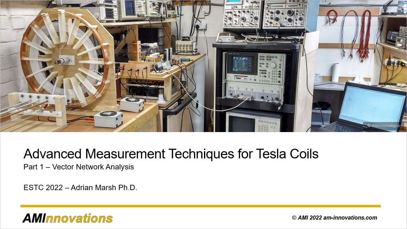
Building, operating, and optimising a working Tesla magnifying transmitter (TMT) system for the maximum transfer of electric power with minimum loss, requires detailed measurement, tuning, and accurate generator and load matching. Measurement of such a TMT system in the frequency domain, using affordable yet sophisticated equipment such as a vector network analyser (VNA), can reveal a wealth of important experimental data. Properly interpreted this data can show how best to operate and tune the system, as well as revealing a deeper understanding of how these fascinating electrical systems work. Vector network analysis is a vast and complex subject which has classically involved considerable training, an established background in electrical engineering, combined with very expensive equipment. The purpose of the presentation at ESTC was to introduce this advanced measurement technique in a simple and practical fashion with equipment affordable to the individual researcher, experimenter, or inventor.
The second video below shows the Golden-Ratio/Fractal-Fern discharge experiment presented at ESTC 2022. Prior to the conference, and in case the equipment did not reach the final destination for the conference, or was damaged in transit, the full experiment was run and filmed in the AMInnovations lab for use at the conference in place of the live demonstration. This video also includes an overview of the equipment used, and the conditions necessary for generation of the Golden-Ratio/Fractal-Fern discharge, which are also covered extensively in the Wheelwork of Nature series.
The third video shows an unplanned live video experiment run during the ESTC 2022 conference which combined the Fractal-Fern demonstration apparatus, and the carbon button lamp made by Griffin Brock[3], who also presented and demonstrated at the conference. The experiment shows a range of interesting plasma discharge phenomena as the button lamp gradually collapses from its vacuum state up to standard air pressure. The range of visual plasma effects give the impression of a solar system in the bulb, followed by the death of the star to become a black hole, and then emerging as a “cosmic” worm hole, and finally the supernova effect breaking out of the containment of the bulb. This experimental sequence of plasma effects has been colloquially named the “Cosmic Worm Hole” experiment.
On the 10th July actually during the 2022 ESTC conference it would have been Tesla’s 161st birthday. In honour and celebration of Nicola Tesla and his monumental achievements throughout his life, we filmed this short video with a model of Tesla in front of the Golden-Ratio/Fractal-Fern experimental system.
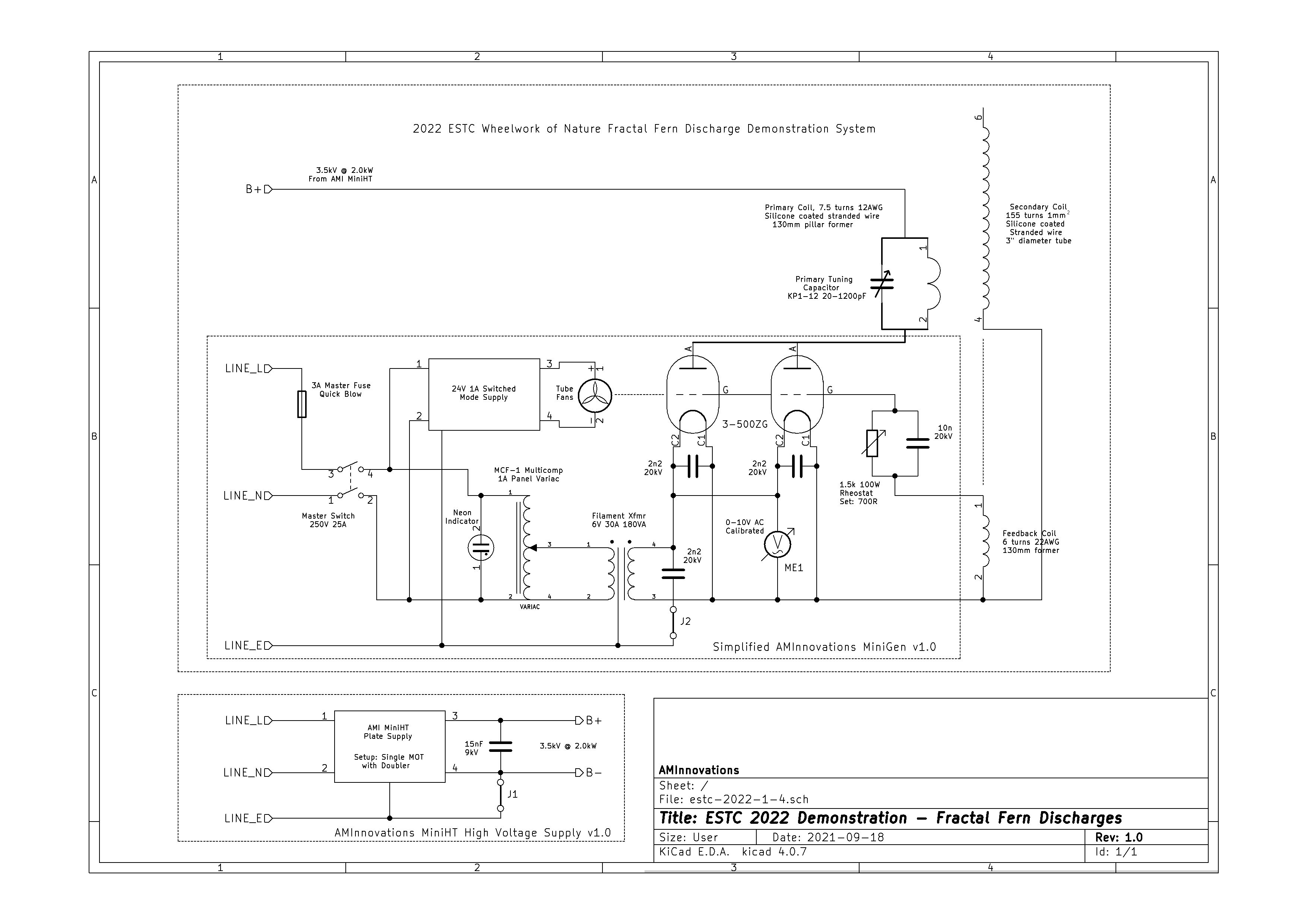
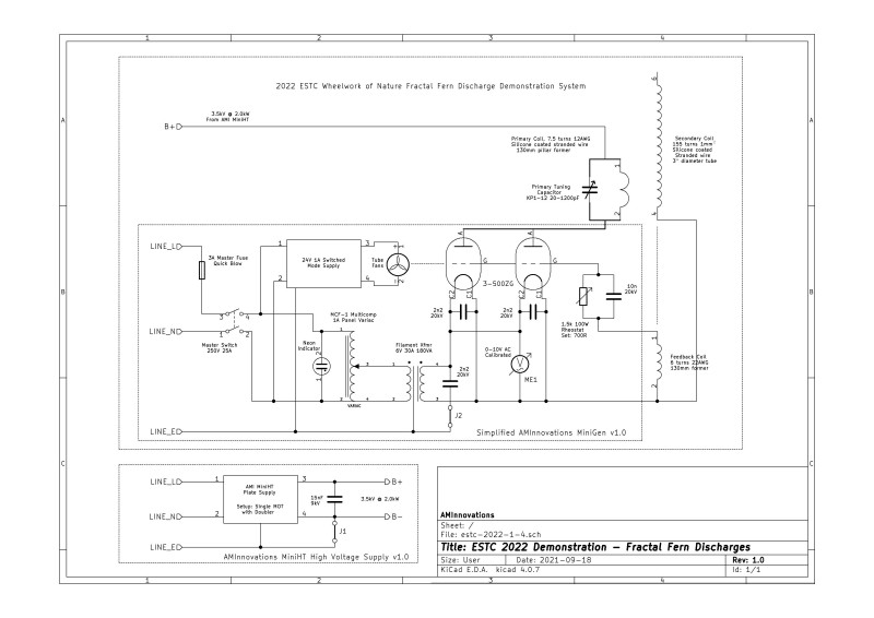
Figure 1 below shows the simplified schematic for the Golden-Ratio/Fractal-Fern Discharge apparatus used at ESTC, which consists of the 2-coil Tesla transformer, and the AMInnovations bespoke Minigen and MiniHT unit, which are specifically configured and matched to produce this special form of plasma discharge when used with the specific coil. The high-resolution version can be viewed by clicking on the following link ESTC 2022 Demonstration.
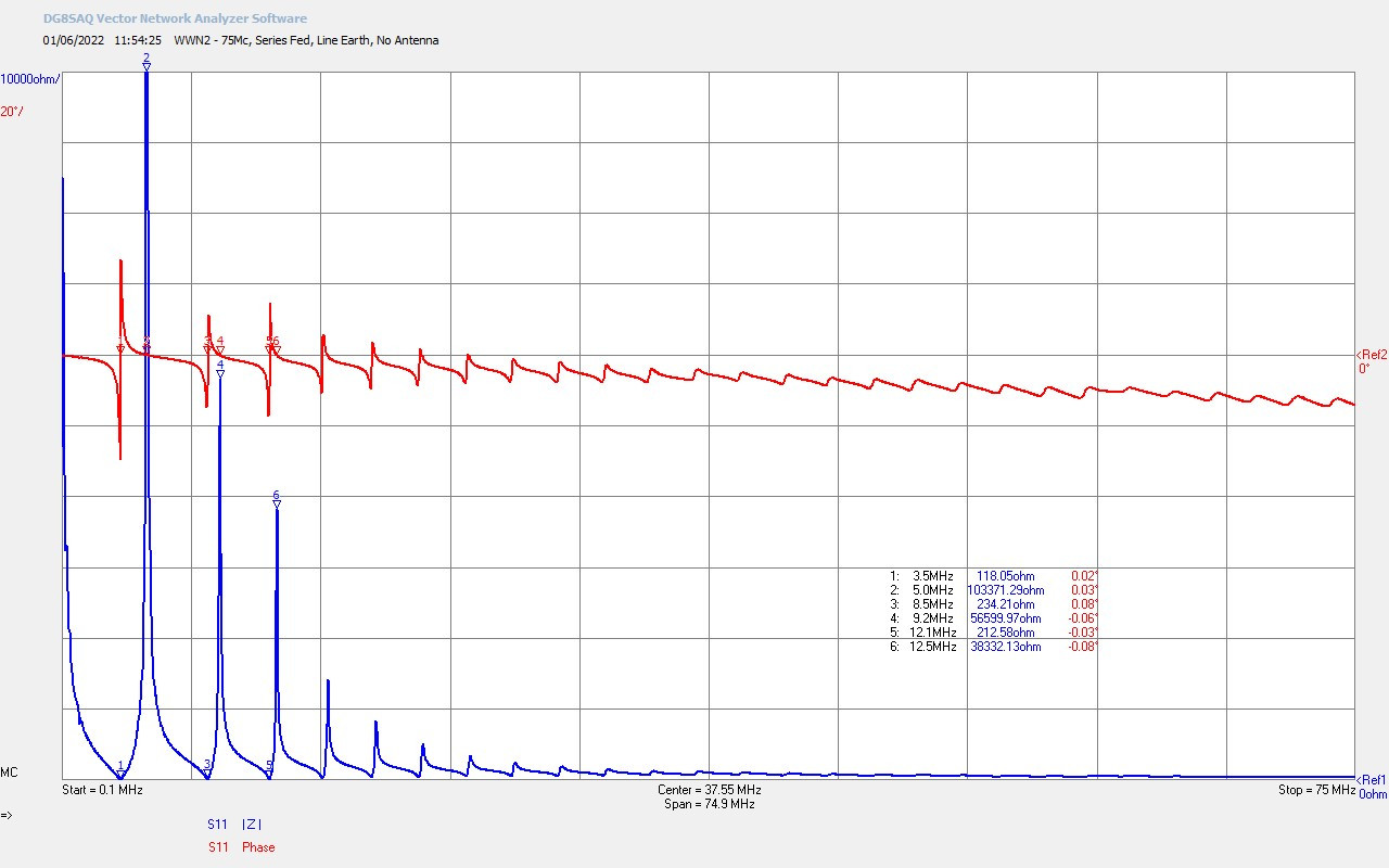
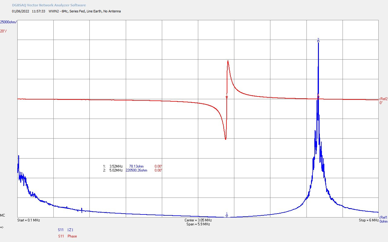
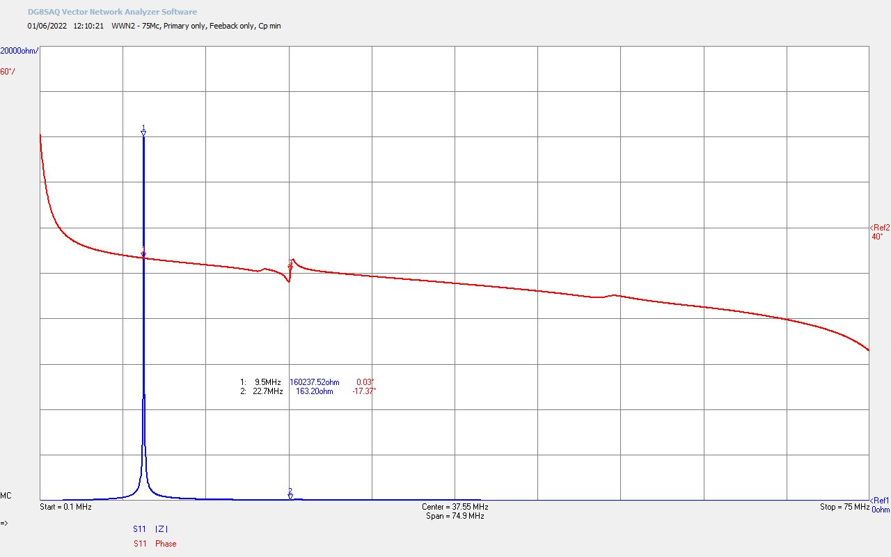
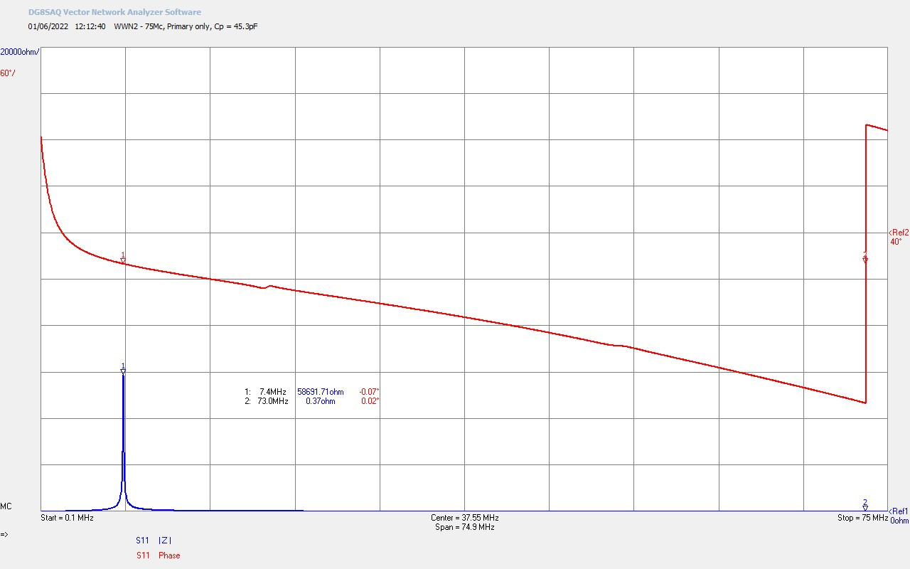
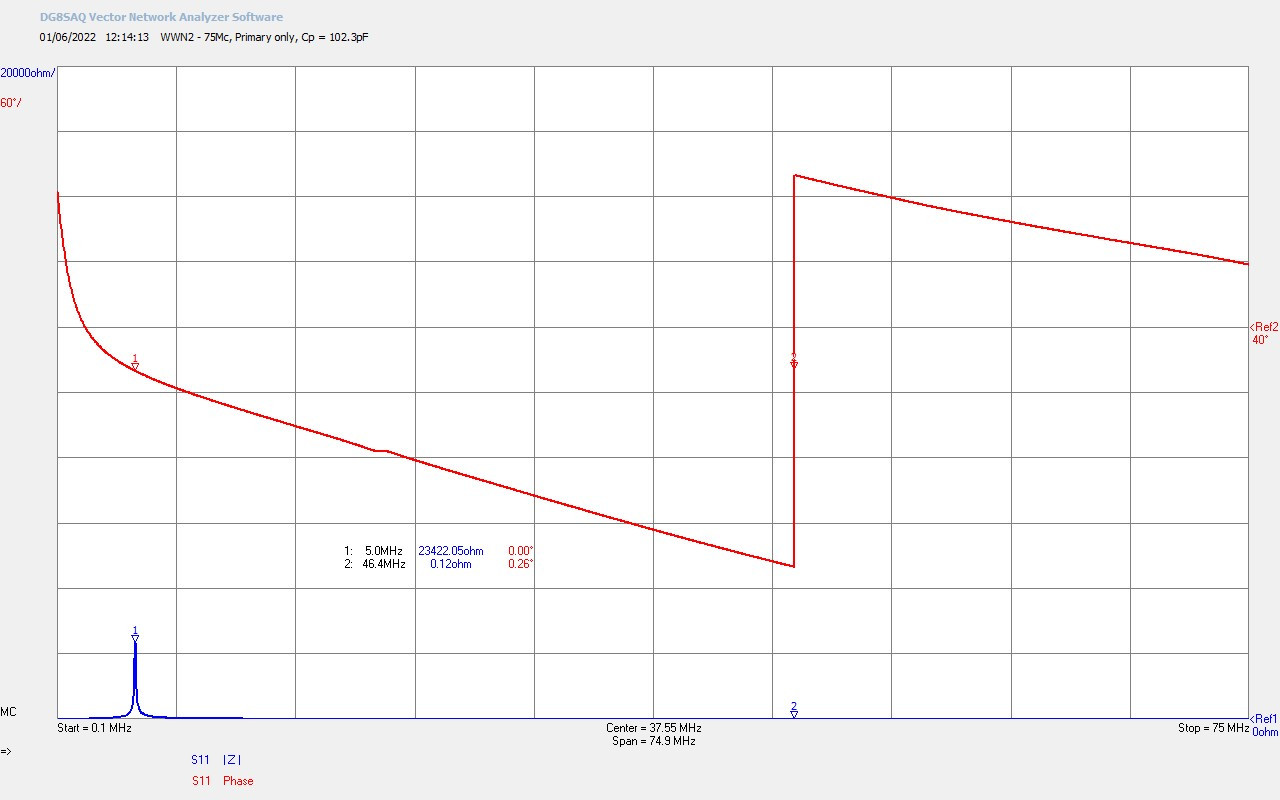
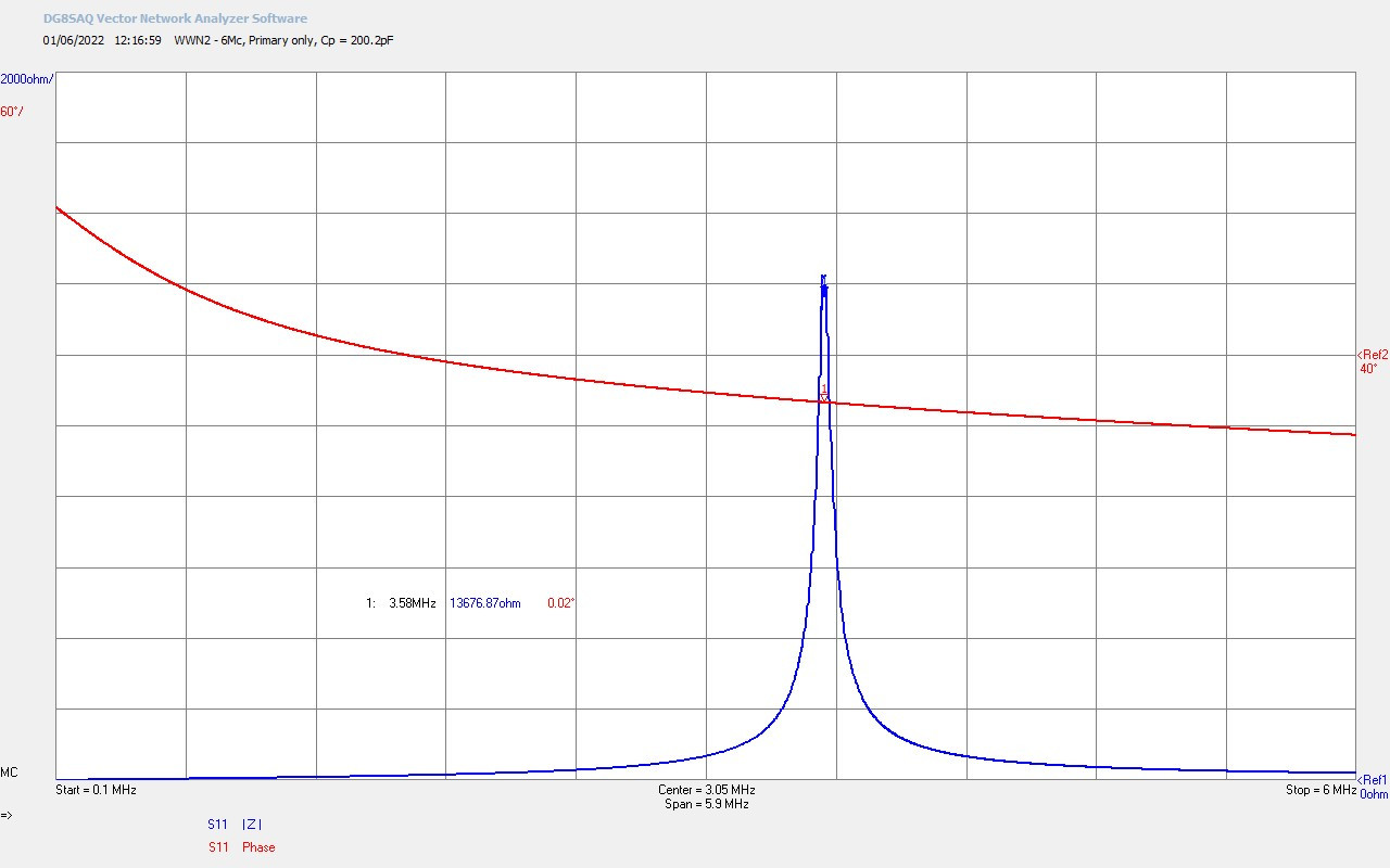
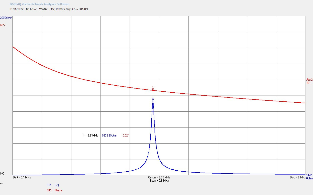
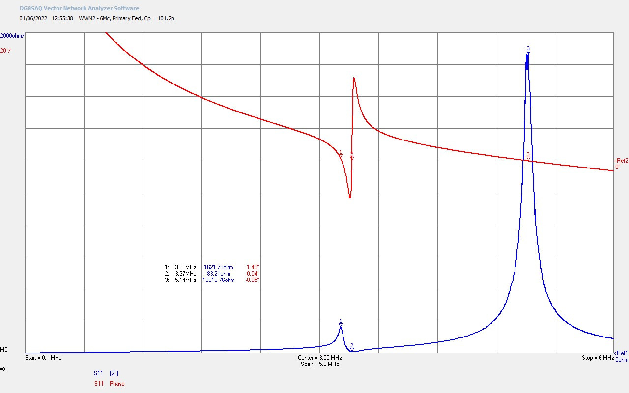
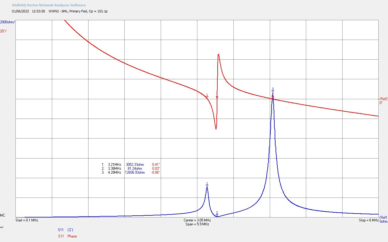
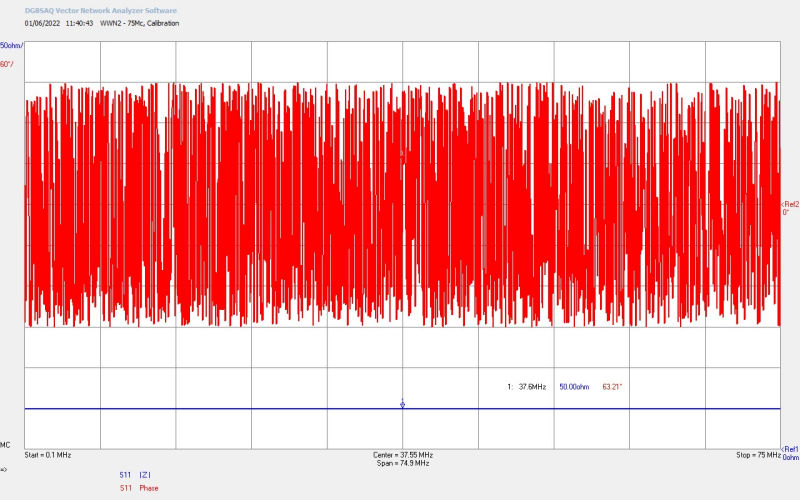
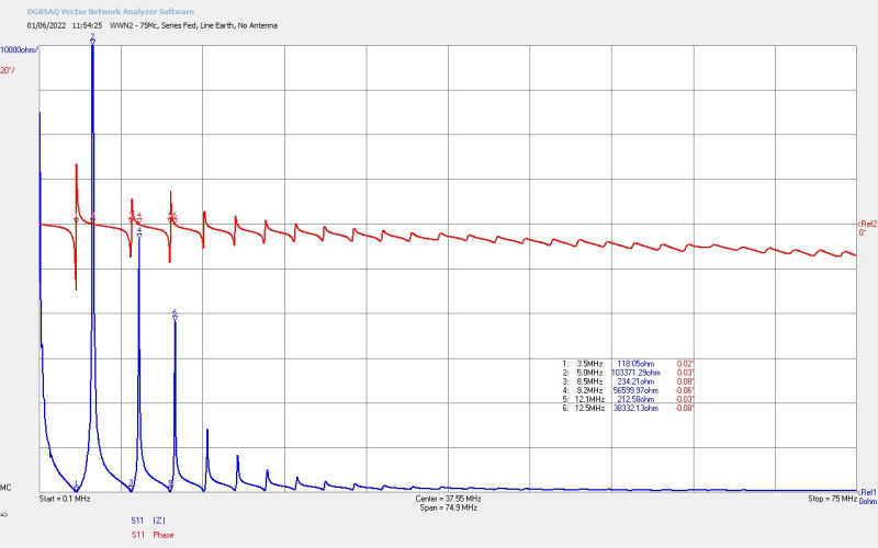
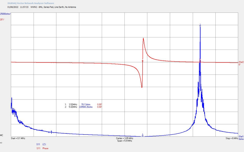
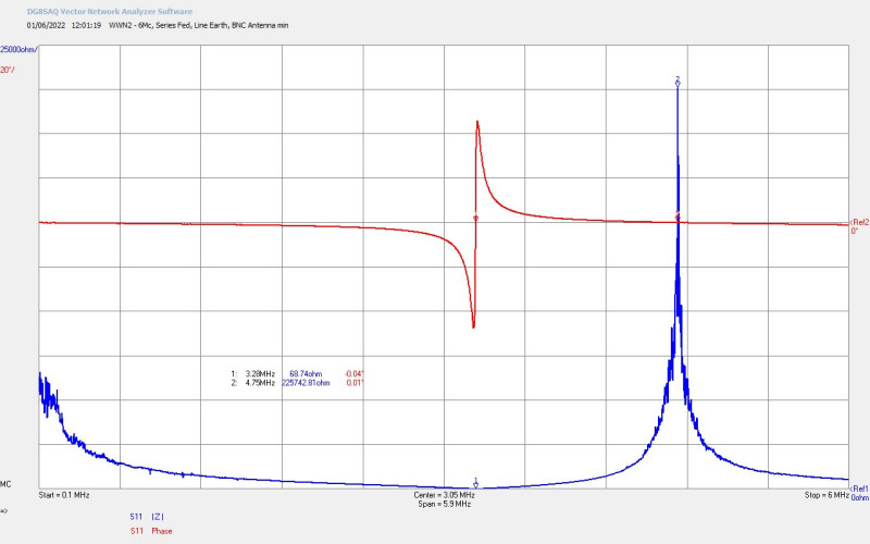
Figures 2 below show the small signal impedance measurements for Z11 for the Golden-Ratio/Fractal-Fern Discharge coil which were measured for the presentation and prior to the conference.


Overall the 2022 ESTC Conference was a great success and AMInnovations played a significant role in contributing high quality and cutting edge science and technology, and culminating in a live demonstration never before seen by the New Science community since Eric Dollard’s demonstration in 1978. The presentation and demonstrations covered the following:
1. A philosophy of science type introduction to the why, how, and what of electrical measurement.
2. An introduction to the properties of Tesla coils, including resonance, coupling, tuning, and matching generators and loads.
3. An introduction to the principles of vector network analysis.
4. Taking a look at equipment suited to this measurement technique both at the high-end, and the affordable end, with a comparison of the range of measurements available from both, and the likely accuracy and limitations which they present.
5. How to calibrate, setup, and prepare a network analyser to measure a Tesla coil.
6. How to make impedance measurements over a frequency band, and interpret the meaning of the measured results.
7. Impedance measurement comparison under different operating conditions, including the effects of coupling, primary, secondary, and extra coil tuning, and loading.
8. How to identify the best points of operation from the measurements, and then optimize the system for the maximum transference of electric power.
9. How to match a generator to a Tesla coil using the measured impedance characteristics.
10. A live measurement demonstration using the Golden-Ratio/Fractal Fern Discharge coil connected to a portable and affordable vector network analyser.
11. A Tesla transformer discharge demonstration using the VNA measured coil to show the Golden-Ratio/Fractal Fern Discharge electrical phenomena for the first time since Eric Dollard in 1978.
1. ESTC 2022, Energy, Science, and Technology Conference, A & P Electronic Media , 2022, ESTC
2. Marsh, A. Advanced Measurement Techniques for Tesla Coils, A & P Electronic Media, 2022, EMediaPress
3. Brock, G. Electrical Investigations & Researches, 2022, GriffinBrock
4. A & P Electronic Media, AMInnovations by Adrian Marsh, 2019, EMediaPress
Telluric Transference of Electric Power – MF Band 110 Miles
In this field experiment telluric transference of electric power is tested in the medium frequency band (MF) at 1860kc over 110 miles. This is the final experiment for now in this series which uses a two-coil TMT (Tesla’s magnifying transformer) system where the transmitter and receiver are constructed with a primary and secondary coil. A new series of telluric experiments will be undertaken using a three-coil system where the TMT coils have a primary, secondary, and extra coil. With the two-coil system at 110 miles, and the ground electrode in the sea, no signal could be detected even when using a portable spectrum analyser with sensitivity down to -110dBm. In the overall series on telluric transference of electric power, the longest distance where a signal could be detected was at 27 miles in a natural lake, and where both radio and telluric-wave components could be measured as contributing to the received signal. Beyond this distance no further signal could be received, using the same TMT system in two very different coastal regions in the UK, at 70 miles on the south coast, and at 110 miles on the east coast. At up to 600W of input power at the transmitter, and a range of variations at the receiver, including with increased magnetic coupling between primary and secondary, no component signal was detected at 1860kc. Other signals could be received from transmitters in the surrounding region forming a control test that the receiver system was working correctly.
The video experiment demonstrates and includes aspects of the following:
1. Portable Tesla receiver (RX) setup and tuning, using a cylindrical coil tuned in the 160m amateur radio band, for radio-wave and telluric-wave field experiments in the far-field region.
2. Telluric ground connection using a submerged aluminium metal plate in the sea on the east coast of the UK 110 miles from the TX.
3. Small signal ac impedance measurements using a vector network analyser, to tune the RX Tesla coil to the series and parallel resonant modes.
4. Received signal measurement using a tinySA portable spectrum analyser, with input sensitivity down to as low as -110dBm across the band 1.5-2.0Mc.
5. Fine tuning to different modes using a telescopic aerial at the top-end of the RX secondary coil.
6. At 110 miles in the sea no result could be obtained down to -110dBm using the portable spectrum analyser, and no audible tone could be detected using the ICF-2001D radio receiver, at either the parallel or serial modes.
7. The spectrum analyser was able to detect signals at 1707kc and 1925kc from other distant transmitter sources, but showed no signal at the experimental frequency of 1860kc.
Video Viewing Note: The wind was very strong in this field experiment, and it is difficult at times to make out the audio, and hence this video is only a short summary of the key highlights of the experiment.
Two-Coil Telluric Transmission and Next Steps
This series of telluric experiments has used the same two-coil system from the close mid-field region at 18m up to the distant far field region at 110 miles, and has demonstrated that a very small telluric-wave component could be transferred between the TX and RX coils of the TMT system up to 27 miles distant. In these basic experiments we are using the earth as a form of telluric conductor or transmission medium, with emphasis on the lowest possible impedance at the ground system connection for both TX and RX coils, and establishing the longitudinal magneto-dielectric (LMD) mode across the cavity of the TMT system. In other experimental series such as High-Efficiency Transference of Electric Power, and in the Transference of Electric Power series, it has been demonstrated that a very high-efficiency of power transfer > 95% could be established in the close mid-field region with a single wire transmission medium up to 11m long. In this scenario it was conjectured that the LMD mode was well established and tuned across the cavity of the system, and it was demonstrated that the tension at the upper end of both the TX and RX secondary coils was very high, and a potential null point was established in the mid-point of the wire. In addition, a varying temporal phase relationship was measured between the voltage and the current along the length of the single wire, and with spatial phase coherence, a conjectured indication that the LMD mode is formed in the cavity.
When the single wire was increased to 30-40m long in the mid-field region the LMD mode was could not be properly established and a large proportion of the transmitted power ~60% was lost to radiation from the single wire in the TEM mode. In the comparative experiment in Transference of Electric Power – Single Wire vs Telluric ~45mW of power was transferred through a telluric channel 18m point to point between the ground system and connections, with 500W of power supplied to the primary of the transmitter Tesla transformer. It was conjectured that almost all of the transmitter power at 1860kc was absorbed into the ground at very close proximity to the ground system, and very little of the supplied power was able to reach the receiver Tesla transformer. This appears to be consistent with increasing distance from the transmitter, as the received signals become progressively smaller and smaller in the far field region. In Telluric Transference of Electric Power – MF Band 2-8 Miles at the first field location 2 miles from the transmitter it was possible to clearly receive with 6 bars of signal strength at only 10W TX power at 1860kc for the telluric-wave and radio-wave combined, and 1 bar for the radio-wave only. The attenuation of the signal at 1860kc under the ground appears enormous, and it was considered again that this loss is dominated by absorption of the transmitter power by the earth directly surrounding the main telluric ground system in the high medium-frequency band.
At the 8 mile man-made reservoir location, although the signal tone could just be detected at 10W TX power, it was necessary to use up to 400W of TX power to get reasonable signal strength up to 4 bars. It was also noted that the ratio of telluric to radio-wave components was around 1 : 1, and the far-field transmission distance had not significantly increased by going up to 8 miles at the transmitter frequency at the top-end of the MF band. It is considered here that the telluric channel/connection at the RX coil end was not as good as for 2 mile case, and especially in taking into account that the water-body used for the telluric ground was both man-made and may not be so well connected to the earth’s aquatic system. It is conjectured that the LMD mode was not established as dominant in the TMT transmission cavity, and that power reception at 8 miles was dominated by the TEM mode of far-field radio-wave propagation.
In Telluric Transference of Electric Power – MF Band 27-70 Miles it was been demonstrated that telluric transference of electric power was possible over 27 miles using a 1860kc cylindrical coil TMT system, although the signal was very small and could only just be detected. At 70 miles no signal could be received either from the telluric-wave or radio-wave. The results received were consistent with those obtained in previous telluric transference of electric power experiments, and also Telluric Transference of Electric Power – Brookmans Park AM Radio Transmitter, where it was demonstrated at 909kc that only ~ 50mW of power could be received at the Tesla transformer receiver 300m (approximately one wavelength) from a 150kW broadcast radio transmitter station.
So the overall conclusions from all these experiments so far in the telluric transference of electric power series are currently as follows:
1. The frequency of the generator in the MF band at 1860kc (and 909kc for Brookman’s Park) leads to very high power absorption losses in the earth close around the transmitter ground system, resulting in very little transferred power through the ground.
2. The tension or “pressure” exerted on the Tesla transformer receiver coil is extremely low even when connected to a ground node, natural water feature, or the sea, and only tiny amounts of power could be received and transformed into the primary circuit at the receiver.
3. The size, extent, and low impedance of the ground connection at both the TX and RX would be critical in the currently investigated telluric transmission in order to minimise signal loss at all stages of the transmission. This huge signal loss across all parts of the transmission medium implies that the TEM mode of transmission is dominant over the LMD mode.
4. This telluric sequence of experiments explores the ground as a simple “conductor” in the form of a single wire transmission medium between TX and RX, and it has been shown at the LMD mode could not be adequately established, or made to be dominate in the cavity of the TMT system.
5. These telluric experiments do not attempt to couple into the earth’s natural telluric currents, through the use of a modulated signal, and hence the high losses through the ground are equivalent to trying to transmit a normal broadcast radio signal in the TEM mode through the ground, which is well understood in electromagnetism to be subject to huge attenuation over only very short distances.
In view of all the experimental results gained so far it appears clear that the transmitter is not able to “push” the transmitted signal from the TX to the RX in the TEM mode through the ground, there is simply no mechanism for this which does not lead to very high absorption of the transmitter power in the earth. At close to medium far field distance the TEM mode can reach the receiver coil both through both telluric-wave and radio-wave transmission, and decays in signal strength over the distance as we would expect for a normal radio transmission. In all the telluric experiments undertaken so far it appears that the LMD mode has not been adequately established between TX and RX outside of the near mid-field region. It is conjectured that in order to establish the LMD mode between TX and RX in the far field it would be necessary to establish a coherent cavity between the two coils, where transmitted power can be “pulled” or “drawn” through the transmission medium to the receiver. It may be possible to establish this coherent cavity using a three-coil system employing Tesla’s extra coil at the transmitter and receiver, which is also a closer reflection of Tesla’s original magnifying transmitter system. It is further conjectured that the extra coil will assist in creating a cavity between the secondary and extra coil, and hence down into the ground system. It may also be possible to establish this coherent cavity by using a modulated signal to couple into the earth’s natural inner telluric currents, and hence the LMD mode established across the natural cavity of the telluric medium through a “resonant” synchronicity between the transmitter, receiver, and the earth.
The next steps are to explore transference of electric power both via single wire and telluric transmission mediums using a three-coil system, where both TX and RX have a primary, secondary, and extra coil. The design and tuning of a three-coil system is more complicated than the two-coil, as we now have two resonant coils which interact through a very short single wire between them, making them a pair of coupled resonators. Coupled resonators transfer energy back and forth between them, “beating”, which results in frequency splitting, and significant shifts in both the series and parallel modes of the resonant system. A study of the impedance dynamics of a three-coil system will be presented in a subsequent post, along with preliminary experiments on the single wire and telluric transmission properties. Modulation is also planned to be introduced, along with experiments at lower frequencies, and ultimately if possible down into the LF-band where Tesla was working with his own experiments. Lower frequency experiments present considerable challenges, including TMT size and scale, generator type and compatibility, radio regulation and licensing, availability of field locations, and resourcing and funding. If these challenges can be overcome then it may be possible to finally confirm or refute the possibility of high-efficiency telluric transference of power, and understand in much greater detail and accuracy the legacy that Tesla has left us to explore.
1. A & P Electronic Media, AMInnovations by Adrian Marsh, 2019, EMediaPress
2. Dollard, E. and Energetic Forum Members, Energetic Forum, 2008 onwards.
Telluric Transference of Electric Power – Brookmans Park AM Radio Transmitter
In this post we continue to explore telluric transference of electric power, by using a Tesla transformer receiver 300 metres from Brookmans Park AM Radio Transmitter. The radio transmitter broadcasts four stations in the medium frequency band (MF) in the south-east of England, and is one of the most powerful AM broadcast transmitters in the United Kingdom, nominally rated at 150kW @ 909kc, and 400kW @ 1089kc, along with two other higher frequencies. A specifically designed and tuned Tesla transformer receiver, which can be tuned both at 909kc and 1089kc for both the series and parallel resonant modes, is used to receive power from the transmitting station, both through the normal transverse radio-wave above the ground, and through the telluric-wave under the ground. This telluric experiment is very similar to the crystal radio initiative (CRI) originally proposed by Eric Dollard, where a Tesla transformer was to be used to power a 100W light bulb using power transferred through the ground from a broadcast AM radio transmitter. The CRI required specific design of the receiving Tesla coil and ground system, optimised for receiving power from the telluric wave. In this experiment we demonstrate a Tesla transformer that receives ~55mW of power combined in the radio and telluric wave, using a very good ground system, and in very close proximity, around one wavelength, to the radio transmitter.
Brookmans Park AM Radio Transmitter[1-3] (BPRT), was designed and constructed in the early 1920s by the British Broadcasting Corporation (BBC) as a powerful dual-frequency transmitter to serve London and the home counties, and replace the dedicated single frequency transmitter in the centre of London. The site was originally developed with twin T-antennas, a form of electrically short monopole antenna which is capacitively loaded at the top in order to maximise radiated power. The twin T-antennas allowed broadcast on two frequencies, and were driven by a tube RF generator housed in the transmitter station, and powered from a series of onsite dynamos, references[1-3] give an interesting and comprehensive early history of the radio station. Subsequently two mast antennas were added to the site, which when phased correctly created a more directional broadcast towards London, and in later years served as individual antennas for more broadcast frequencies. Today the Brookmans Park site transmits on four AM frequencies, and has a range of satellite telecommunications, and FM applications. The video experiment includes a brief walk through Brookmans Park to see the various antennas, layout, and considerations as to their applicability to telluric transference of electric power experiments. Although four frequencies were available at BPRT[4], 909kc @ 150kW, 1089kc @ 400kW, 1215kc @ 125kW and 1458kc @125kW, the two lowest frequencies were selected as the most suitable for telluric transference of power (keeping the frequency as minimum as possible), and of these two, 909kc was found to produce the best power output at the receiver, (even despite 1089kc being at a higher transmitter power).
The crystal radio initiative[5] was devised by Eric Dollard on the Energy Science Forum[6] around 2012, with the objective, “to scale a crystal radio set, a step at a time, into a Tesla Transformer for the reception of medium wave band, 300–3000kc AM broadcasts” … “A Tesla Magnification Transformer, properly proportioned can, in theory, actually draw power from a local 50 kW station. Several hundred watts of power reception is likely. This would prove Tesla once and for all, no antenna, just a good ground, and a nice and bright 100 watt light bulb”. In conventional broadcast radio transmission a monopole antenna, such as a vertical mast or T-antenna, consists of a radiating mast above ground, and a radial conductive ground plain, usually buried just below the surface of the ground, and consisting of many copper radial conductors extending from the base up to a quarter wavelength away from the mast base. The generator via a tuning network, is connected directly across the vertical mast and the radial ground-plane and transmits a vertically polarised radio-wave omni-directional from the mast. The radial ground plane must be a very low impedance at the transmitted frequency, typically < 2Ω, and is intended to properly terminate the displacement current from the vertical mast, forming a very low return impedance to the generator. In this way losses in the system are minimised and the broadcast transmitter is optimised for maximum transmission of the radio-wave, (or ground-wave in normal radio terminology, and not to be confused with the telluric-wave).
At Brookmans Park at 909kc the transmitter is nominally rated at 150kW. Now if only 1% of this power were able to escape through the ground-system then up to 1.5kW may be available for transference to a receiver system. For this to happen in the MF band the power needs to not be absorbed by the earth, and also be in the correct transmission mode. The radio transmitter is a conventional transverse electromagnetic (TEM) transmission source, and the Tesla transformer receiver is designed for the longitudinal magneto-dielectric (LMD) mode formed in the cavity of the secondary. In a Tesla Magnifying Transformer system (TMT) where both the transmitter (TX) and receiver (RX) are LMD transformers, it is conjectured that large amounts of power can be transferred at high efficiency over very large distances, with very low losses, and at very low frequencies ~ 45kc. In this experiment and in the CRI case we have a TEM transmission mode radio transmitter at 909kc, with what would be considered leakage power from the ground system, and provided this power is not absorbed by the earth, could be transferred to an LMD Tesla transformer with a good ground system via the telluric wave. This is the case of a TEM TX transformer with an LMD RX transformer, and at a higher frequency that is easily absorbed in the earth, so it forms a particularly interesting experiment to see what level of power, if any, can be received by the Tesla transformer receiver, and what level of load could be driven from this harvested power.
The video experiment demonstrates and includes aspects of the following:
1. An introduction to Brookmans Park AM Radio Transmitter Station, broadcasting 150kW @ 909kc, and 400kW @ 1089kc, along with two other additional AM frequencies.
2. The configuration of the vertical mast and T-antenna monopole antennas on the site, to form a phased directional transmitter (TX), and optimised for ground-wave transmission of the transverse electromagnetic mode (TEM).
3. A brief introduction to Eric Dollard’s crystal radio initiative (CRI), the challenge to power a 100W incandescent lamp using a Tesla coil transformer, and using an AM Broadcast radio station as the generator.
4. A modular Tesla coil transformer receiver (RX) designed to tune both the parallel and series resonant modes to 909kc and 1089kc, corresponding with two of the station’s transmitting frequencies, and optimised for the longitudinal magneto-dielectric (LMD) transmission mode.
6. At 300m from the transmitting station antenna, in the near-field and within the induction field of the TX, a maximum of ~55mW of power could be measured using an HP435B with HP8481H thermocouple sensor, and with RX tuned to the parallel mode at 909kc, and using a tested good ground connection.
7. The telluric wave was measured to contribute ~39mW to the total received power, and the radio wave ~16mW of power, showing that more power was received directly through the telluric channel between TX and RX.
8. The received power was sufficient only to power an LED, and no significant voltage tension was measured across the secondary coil terminals. A 0.5W and 3W neon lamp, along with a 5W incandescent lamp could not be illuminated.
9. It is conjectured that the very low received power of ~55mW from a transmitter output of up to 150kW only 300m distant, results from a combination of the following:
a. The mismatch between TX (TEM) and RX (LMD) transformer modes.
b. High absorption of power by the earth close to the TX ground system at 909kc.
c. Inadequate electrical tension developed across the secondary coil of the Tesla transformer receiver, which suggests no LMD mode is developed between TX and RX transformers.
Design of Tesla Transformer Receiver coil
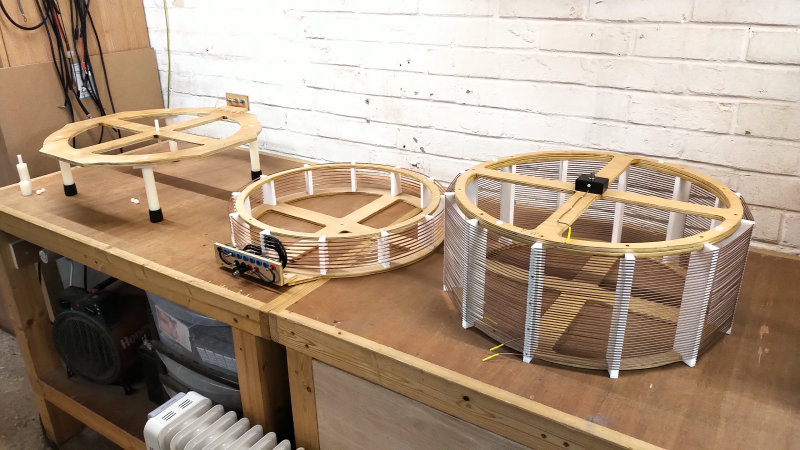
Telluric transference of electric power experiments thus far reported on this website have been conducted at 1860kc in the 160 metre amateur band, and using a Cylindrical Coil design. These experiments have demonstrated so far that 1860kc in the MF band is too high a frequency for a Tesla TMT system, as almost all of the RF power is absorbed by the earth in very close proximity to the transmitter ground system. In order to improve on these experiments lower frequencies are being investigated, and including this experiment at 909kc at Brookmans Park. Operating at lower frequencies means larger coils, and hence it was considered to design a more modular coil system consisting of a generic base, and with interchangeable, and extendable primary and secondary coil systems to work at a range of different frequencies, both with and without an extra coil.
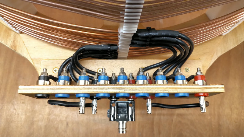
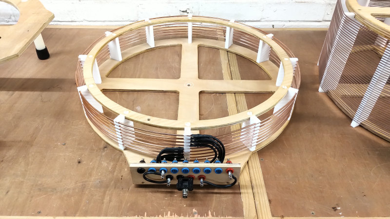
For the opening experiment at Brookmans Park a dual frequency secondary coil was designed to allow the receiver to work at both 909kc and 1089kc for both the series and parallel modes of the coil. The primary was developed to have up to 8 configurable turns to tune the optimal balance between quality factor of the resonant mode, and the magnetic coupling coefficient k between the primary and secondary coils. The primary coil turn number and position can be selected via a jumper system on a turn by turn basis from only 1 turn, up to a full 8 turns. In practise and after measurement 6 turns of the primary was found to be optimal for the secondary coil used, and this will be considered later in the small signal ac input measurements.
The design of the Tesla transformer receiver starts with the secondary coil, and using design characteristics previously empirically determined to be optimum for transference of electric power experiments using a TMT system. Much more detail on these characteristics and how they were determined can be found in the experimental and measurement posts in Transference of Electric Power, and Tesla Coil Geometry and Cylindrical Coil Design. For this design without an extra coil the following was used:
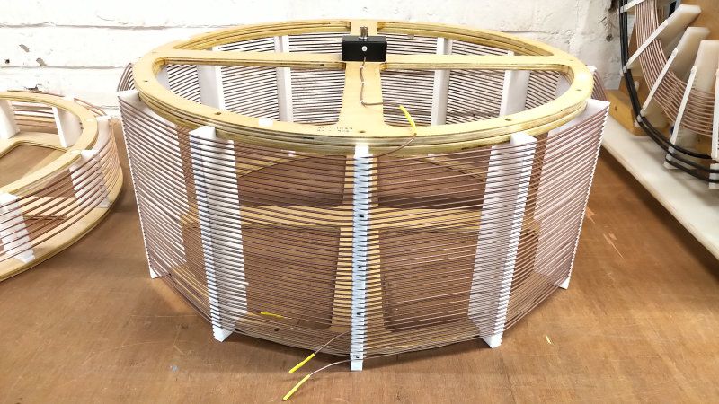
1. A low aspect ratio width to height, loosely wound, cylindrical coil section, based on a 56cm diameter coil which can be used into the low-end of the MF frequency band, down to ~ 475kc with additional secondary coil sections added in a modular construction, or with a third extra coil design.
2. A secondary conductor spacing-turns ratio of ~63%, using a 1.85mm diameter RG178 coaxial conductor with a 5mm turn pitch.
3. A primary conductor with spacing-turns ratio of ~67%, using a 3mm diameter copper tube with a 9mm turn pitch.
4. A vertically stacked primary and secondary with ~25-50mm spacing between coils, and dependent on the configuration of secondary coil frequency (909kc or 1089kc).
5. Possibility for selection of equal weights of conductors in the primary and secondary coils through primary turn number, and to be best balanced with the impedance, quality-factor (Q), and magnetic coupling coefficient k between both coils.
6. Theoretical resonant frequency for 909kc and 1089kc to incorporate a telescopic aerial at the secondary top-end to tune the series or low parallel resonant mode of the Tesla transformer to the exact frequencies of the radio transmitter. In this case the theoretical design needs to add between 100-150Hz to the desired resonant frequency, which will then lower to the target frequency with the addition of the telescopic aerial.
With consideration of these design characteristics the theoretical secondary coil design using Tccad 2.0 is as shown in Figures 1 below.
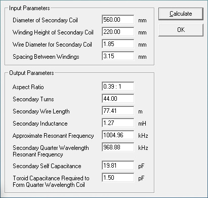
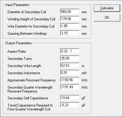
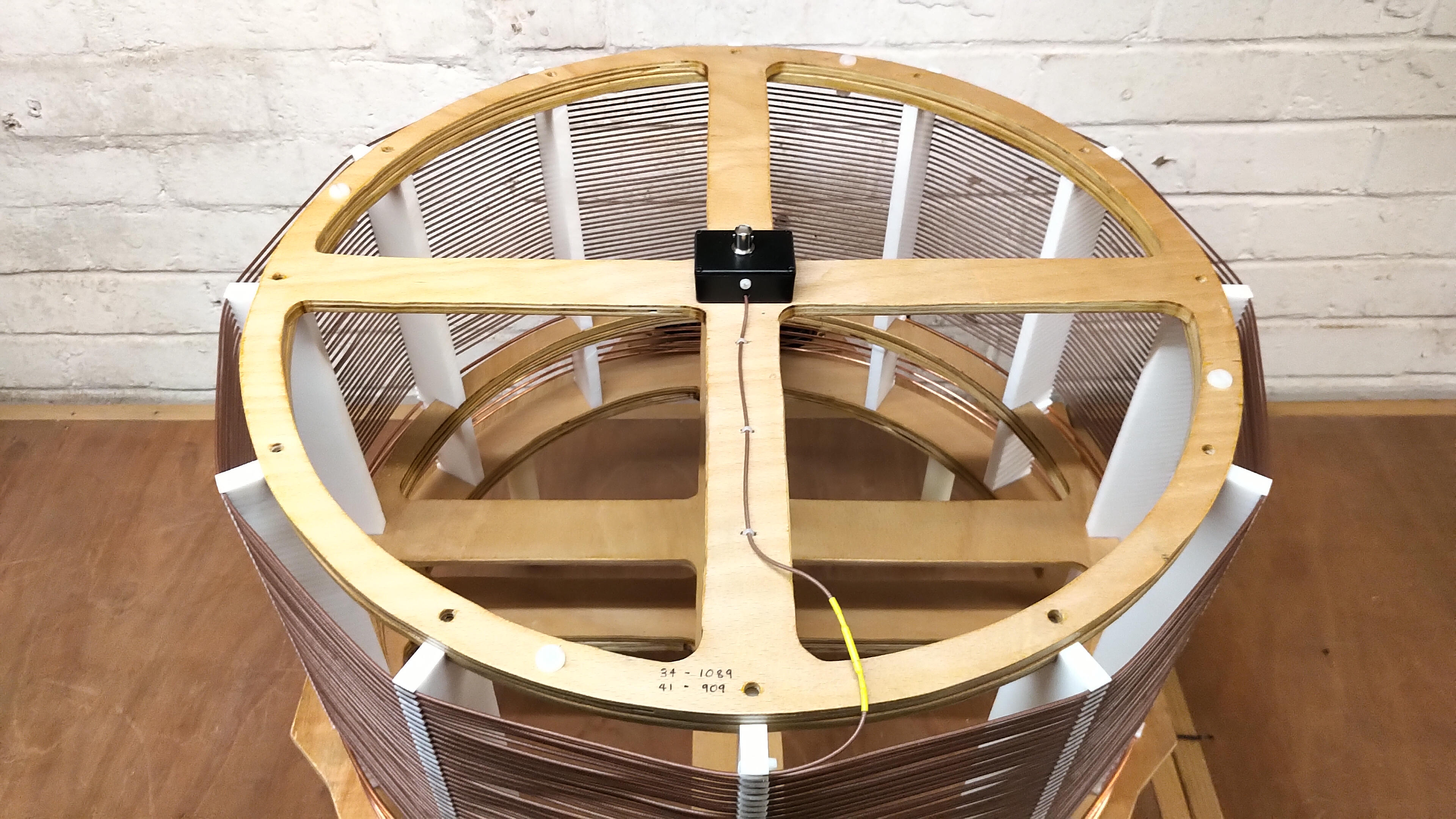
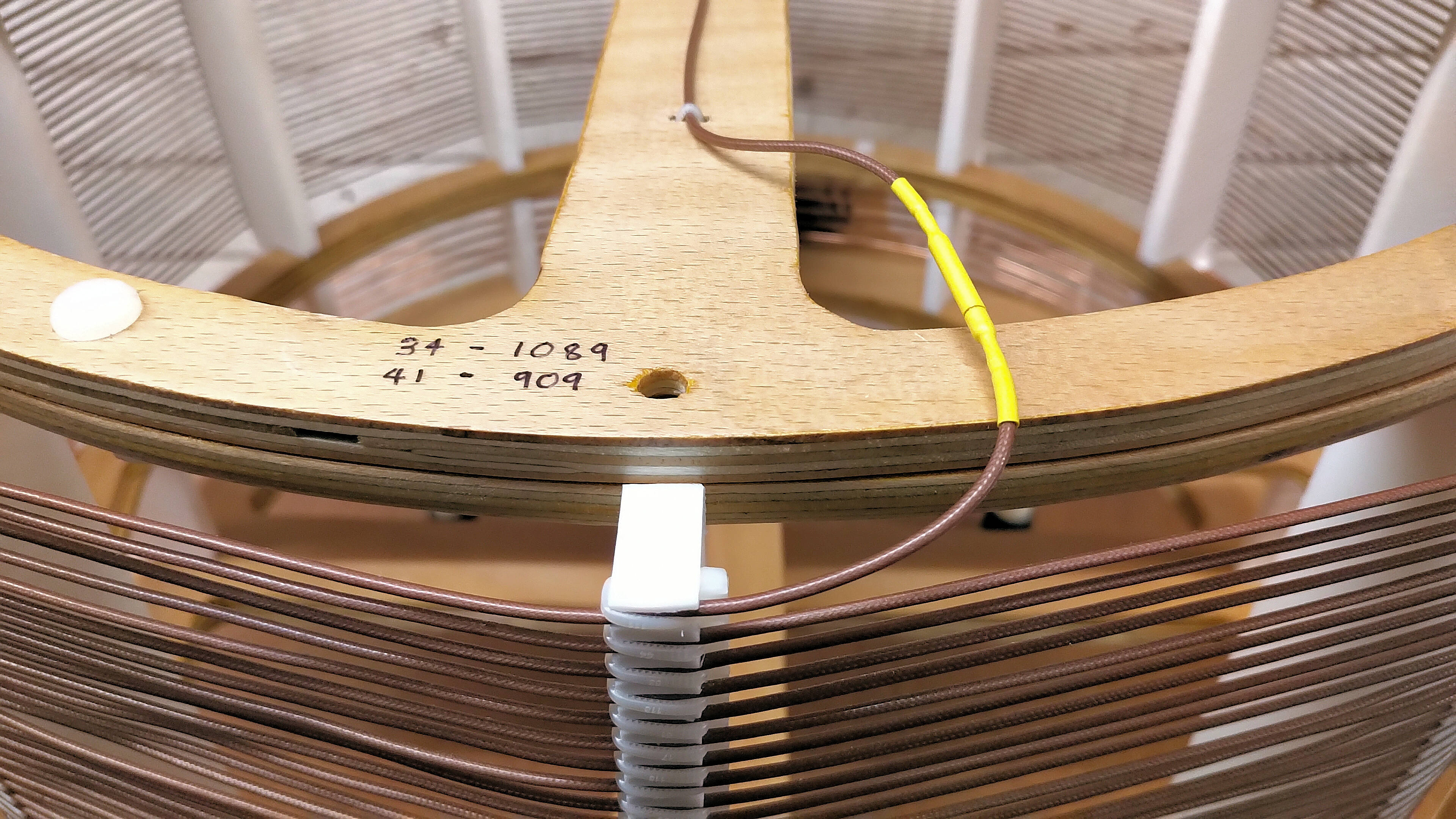
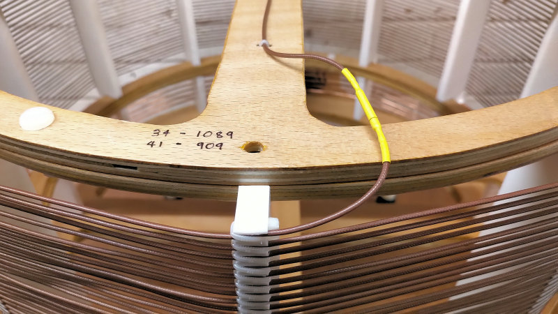
In practise when the small signal ac impedance measurements were made with the DG8-SAQ USB vector network analyser (VNWA) the number of turns were reduced slightly from the theoretical design. With the telescopic aerial at a minimum extension of 15cm at the secondary top-end, and a good RF ground connected to the secondary bottom-end, the lower parallel mode could be tuned for 1089kc with 34 turns, and for 909kc with 41 turns. In both cases with the telescopic aerial maximally extended, the series mode could also be tuned at 1089kc and 909kc, providing flexibility and simple configuration during the field experiments.
The 1089kc coil was wound with a 2mm terminal connector at each end, so the additional 7 turns for the 909kc could be added at the lower end of the coil without any need for unwrapping windings from the coil former. The extra turns can be placed at the top or bottom-end of the secondary coil, but in this case the bottom-end was used to add extra turns, and in order to simplify tuning at the high impedance end of the coil, where the quality factor and magnification is at its maximum. Adding turns at the bottom-end also requires a change in configuration of the primary coil turns (by the jumpers), in order to accommodate for the change in magnetic coupling coefficient k with increased physical distance between the 909kc and 1089kc coil bottom-end. The optimum number of primary coil turns to start with is determined during the small signal ac impedance measurements, and then adjusted slightly up or down during the actual field experiment.
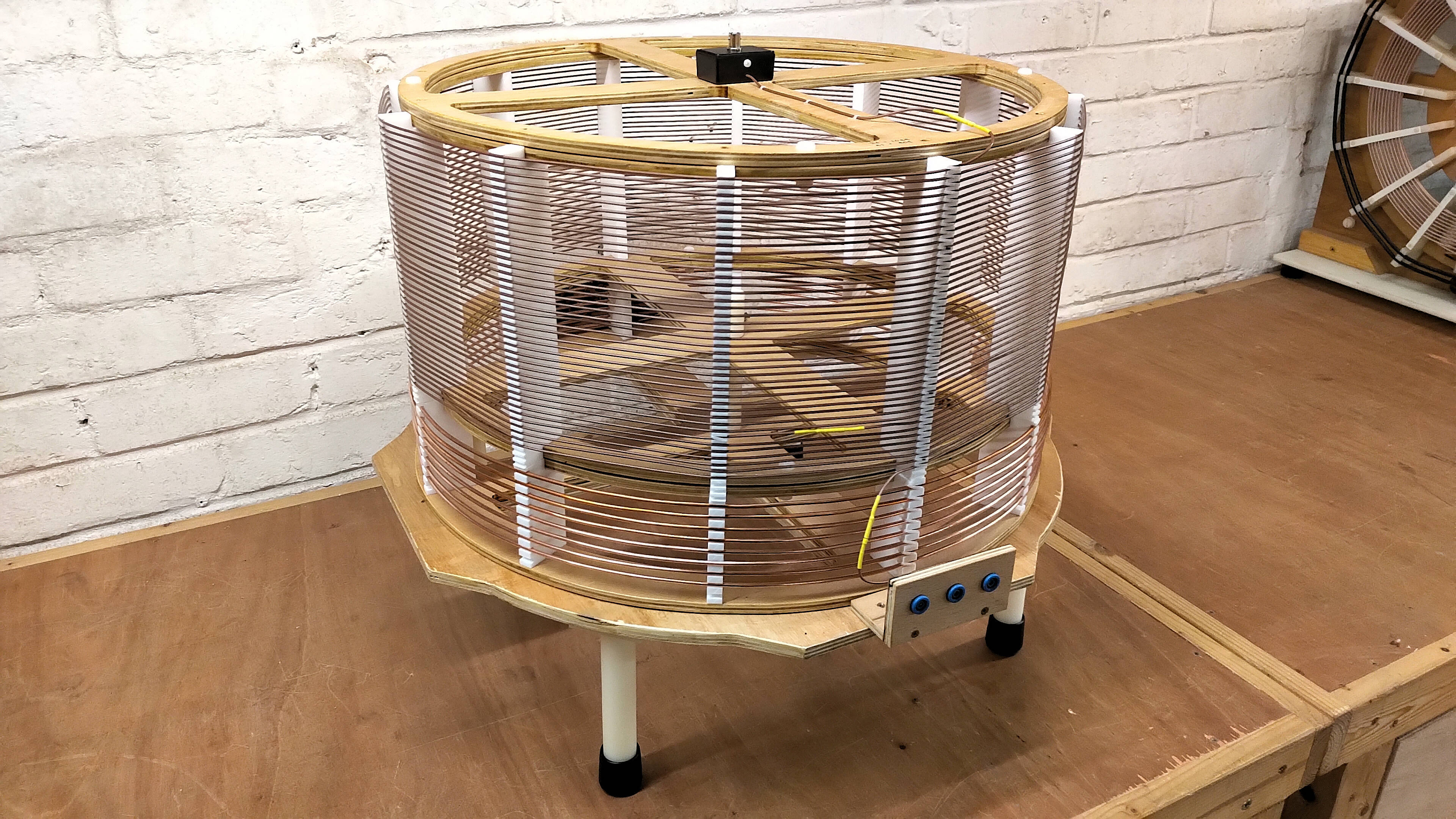
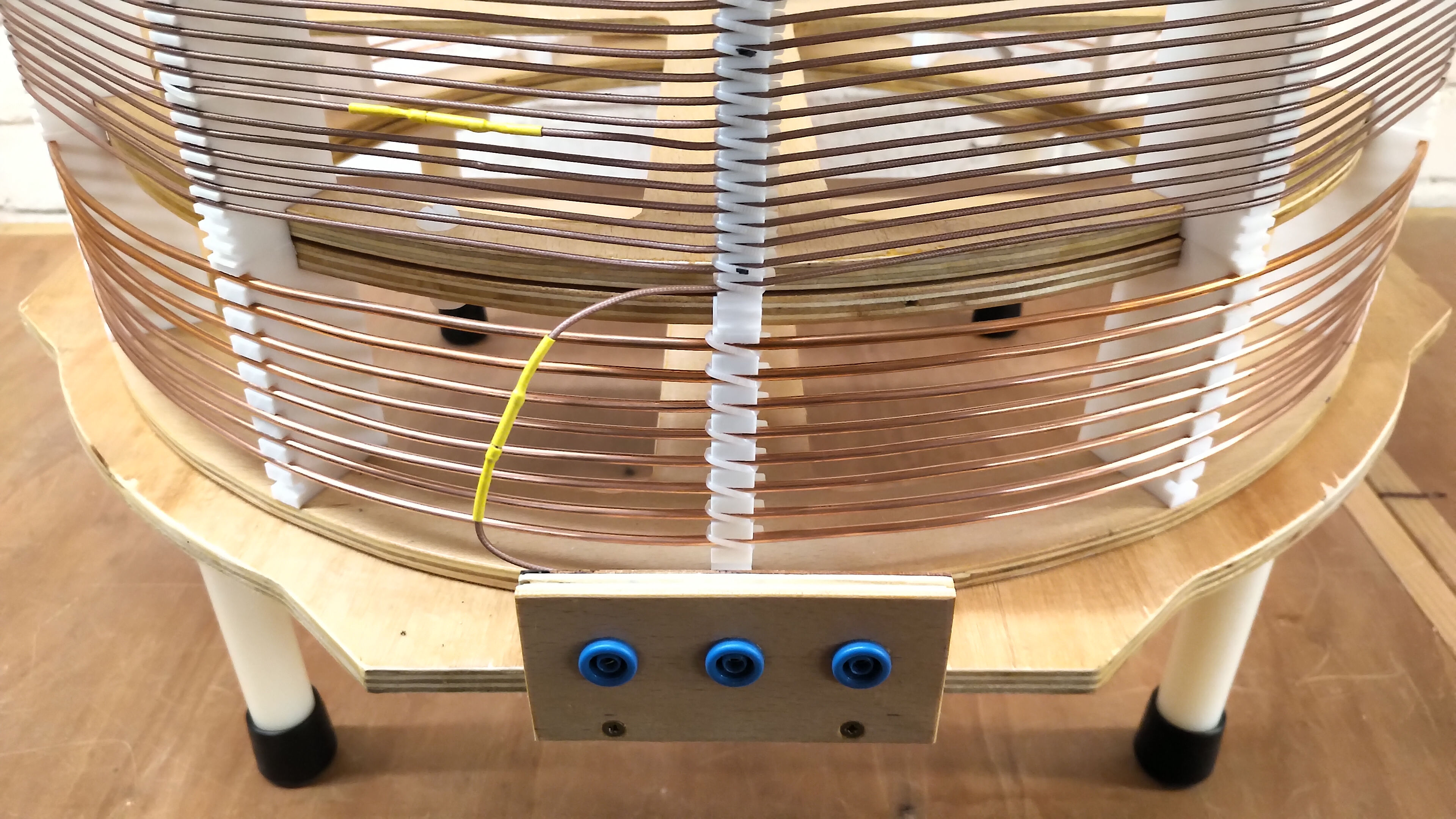
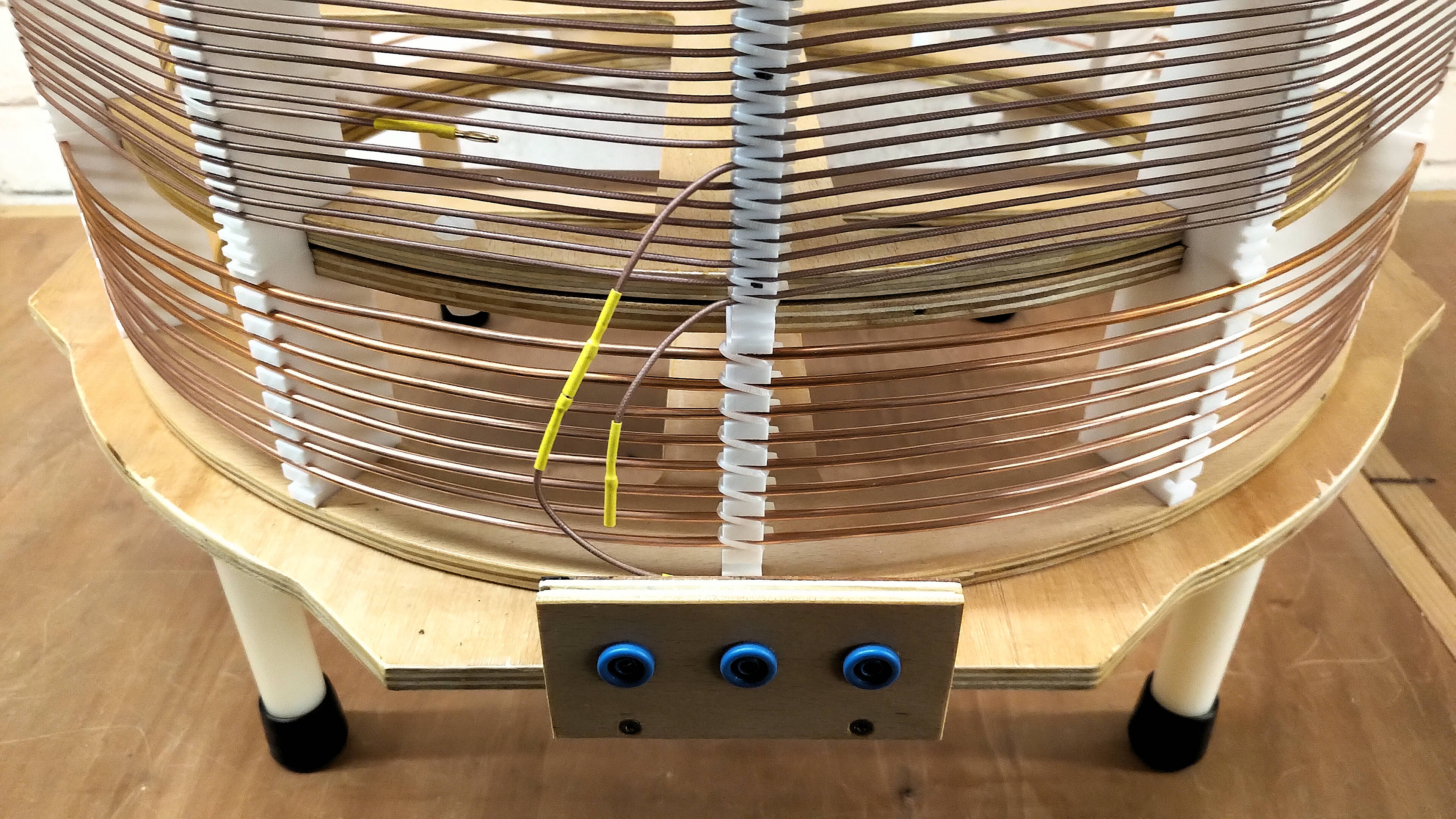
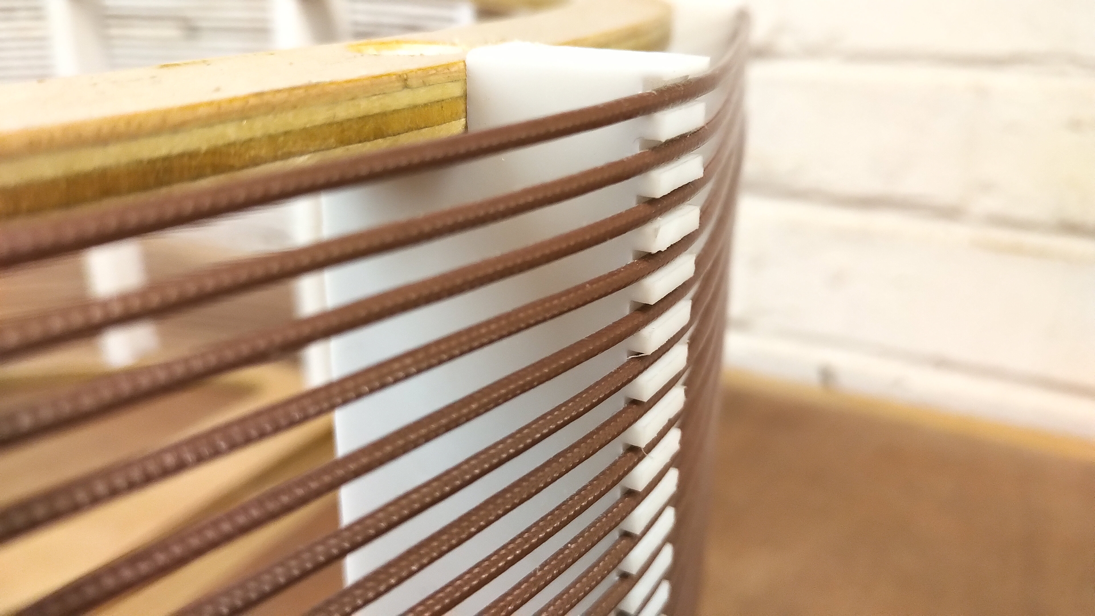
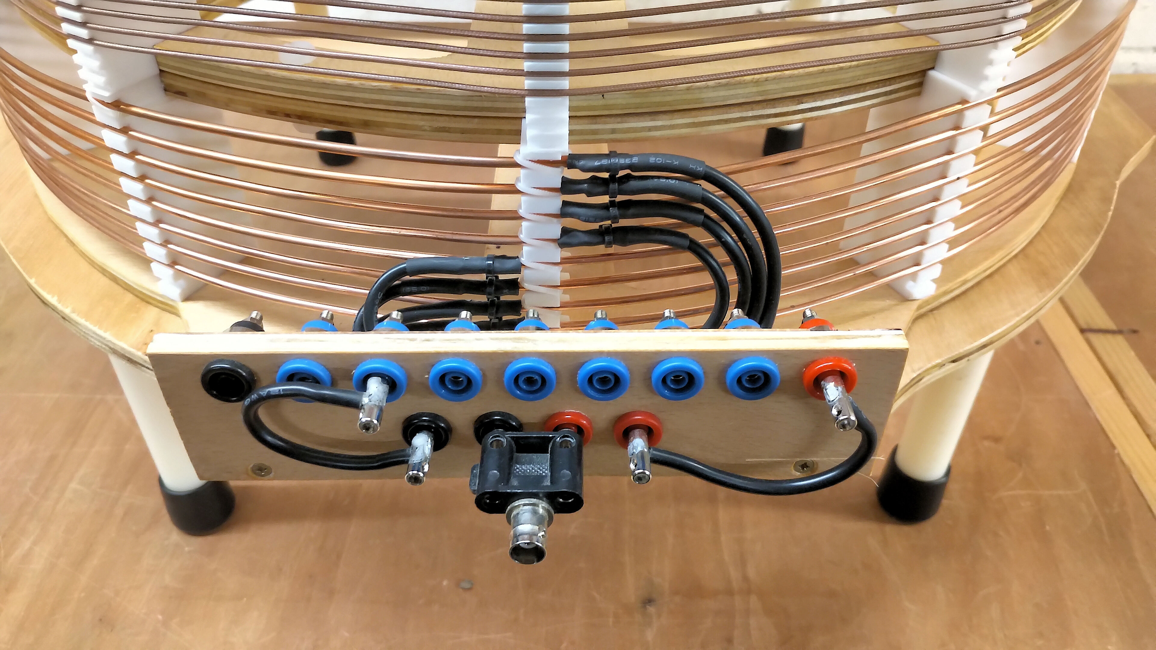
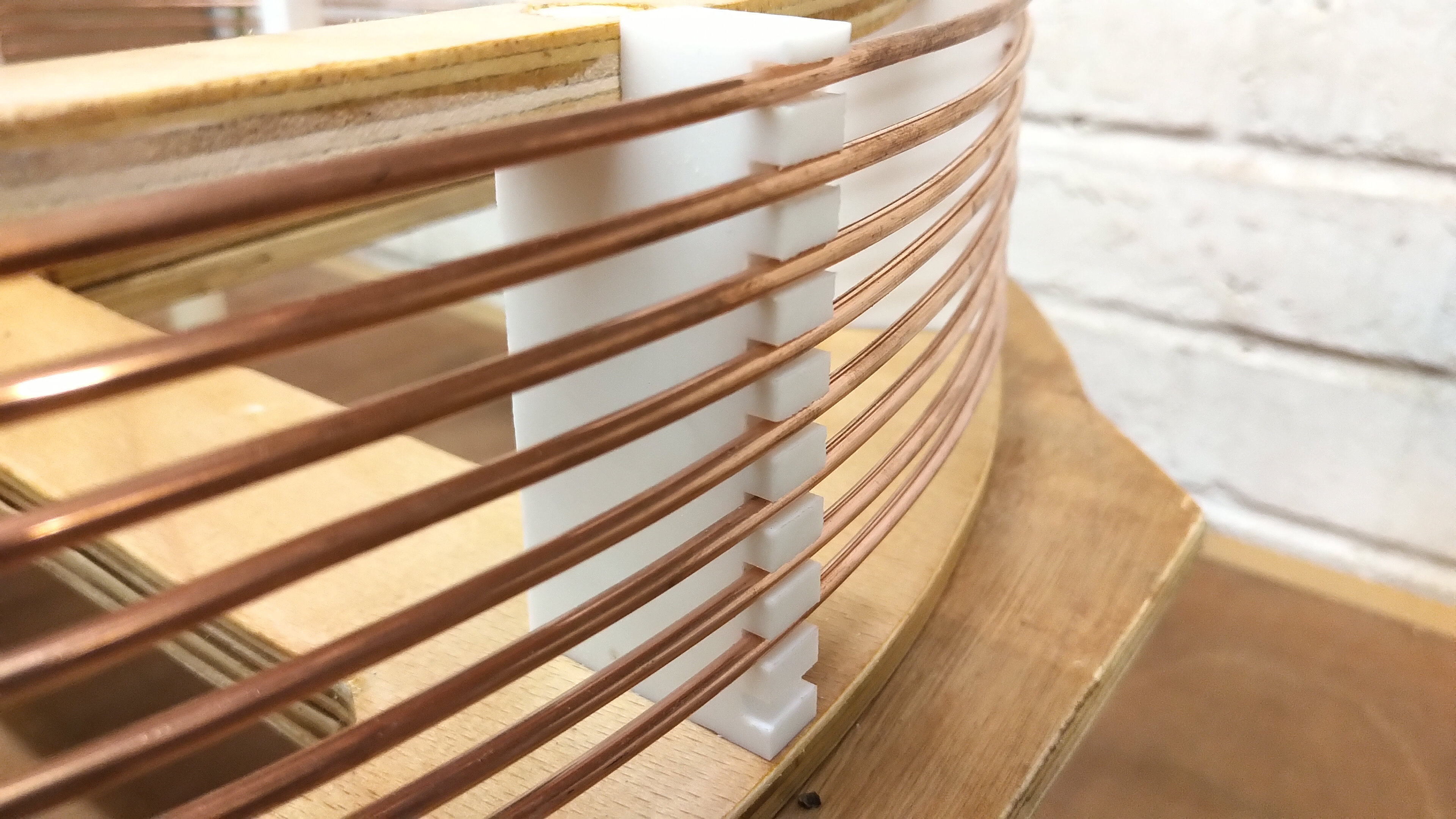
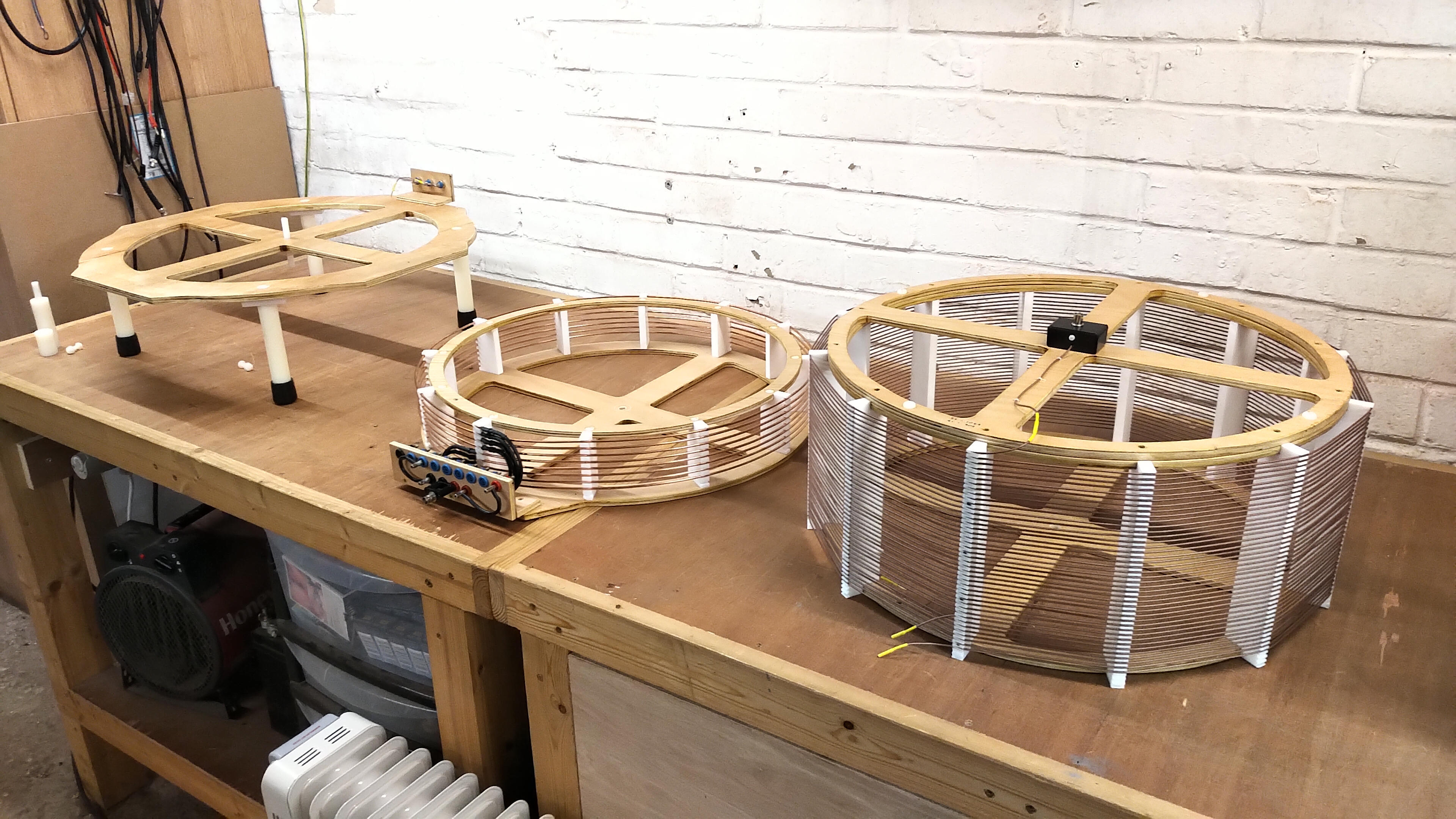
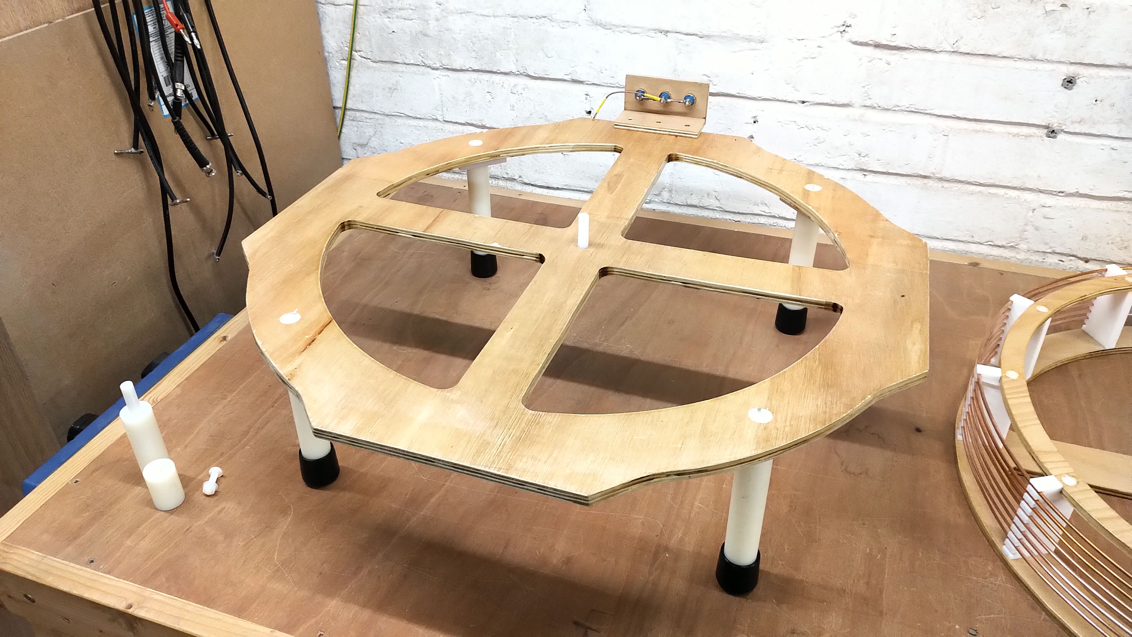
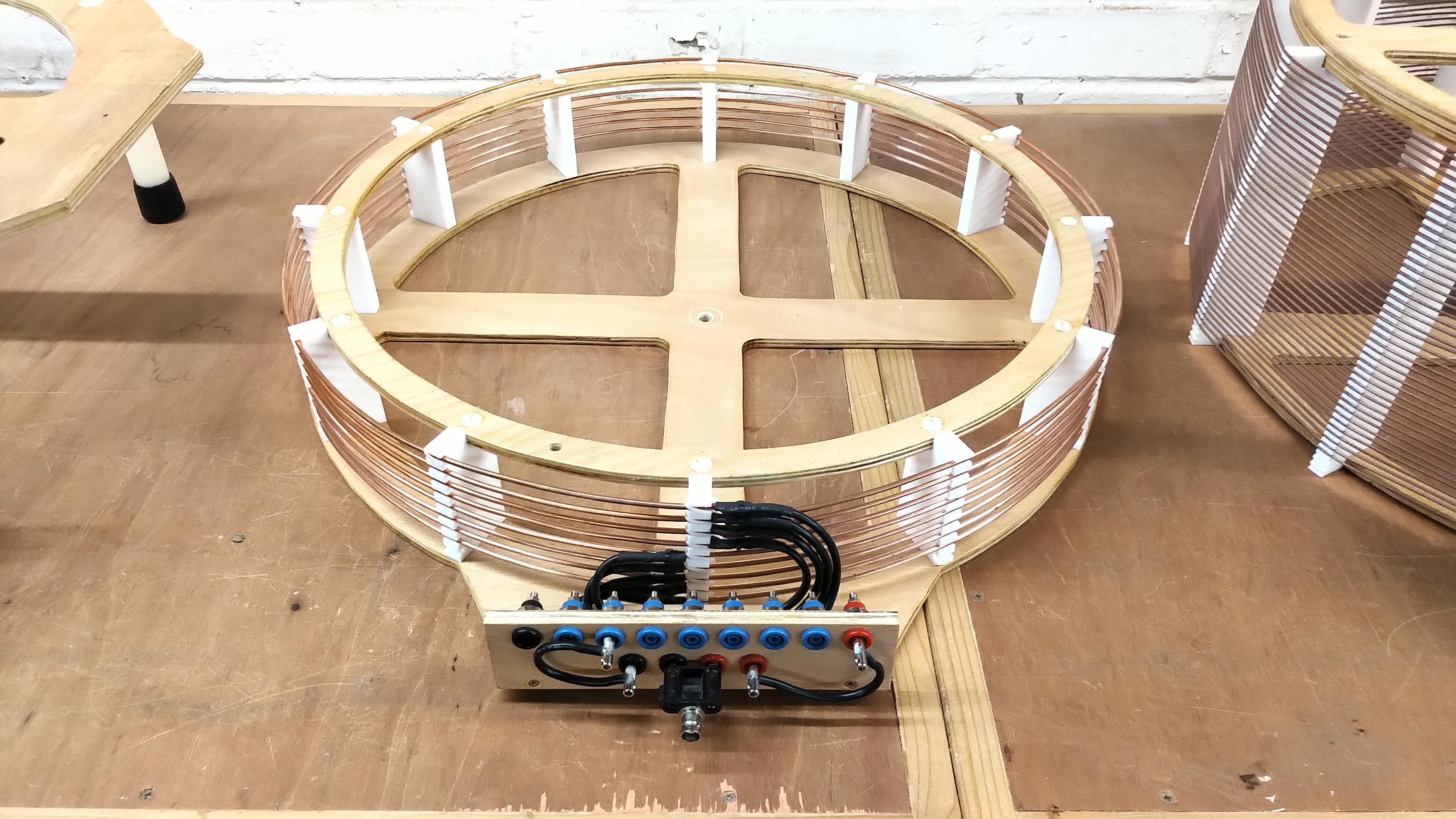
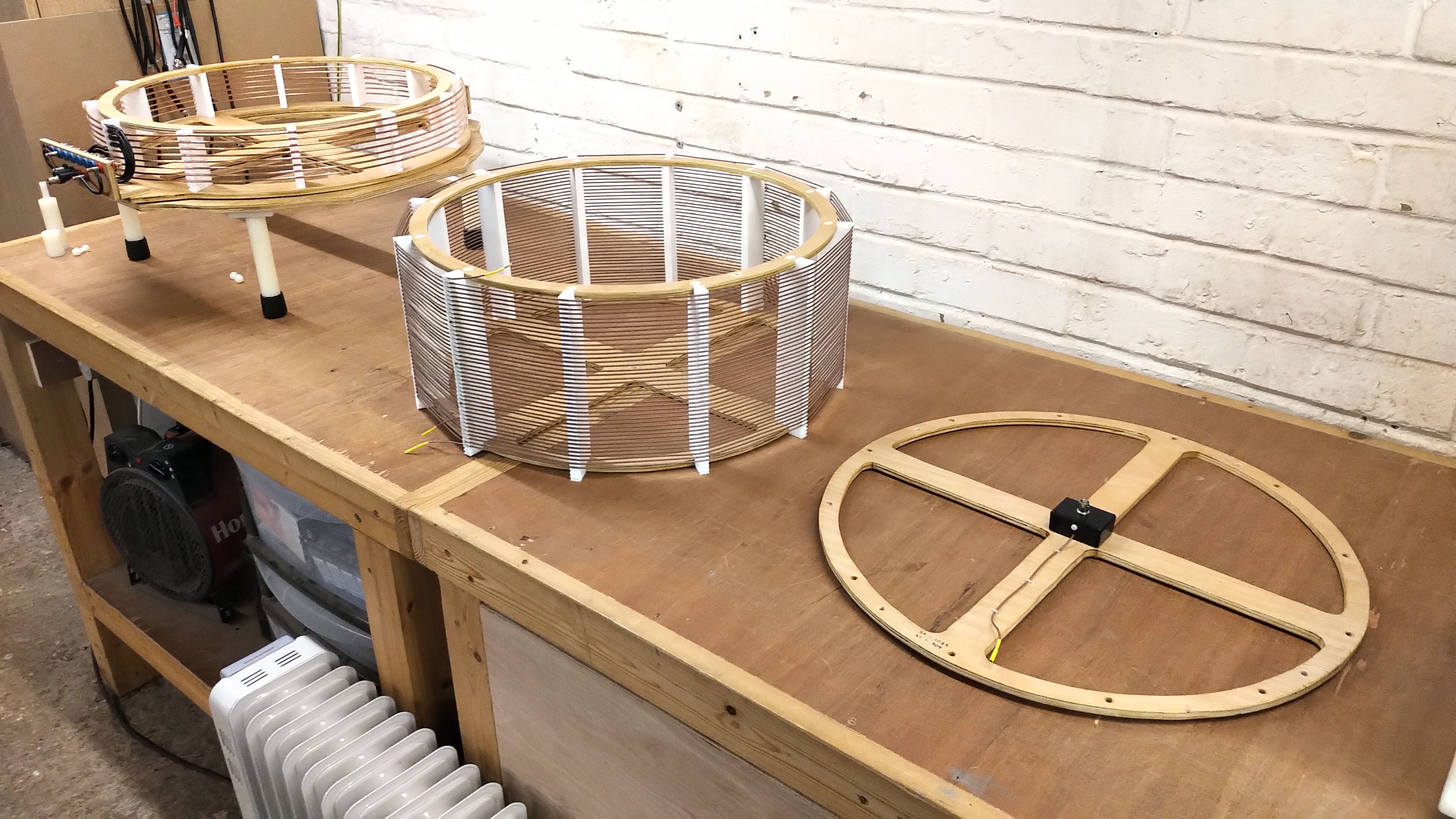
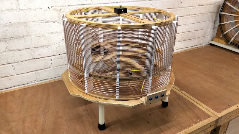
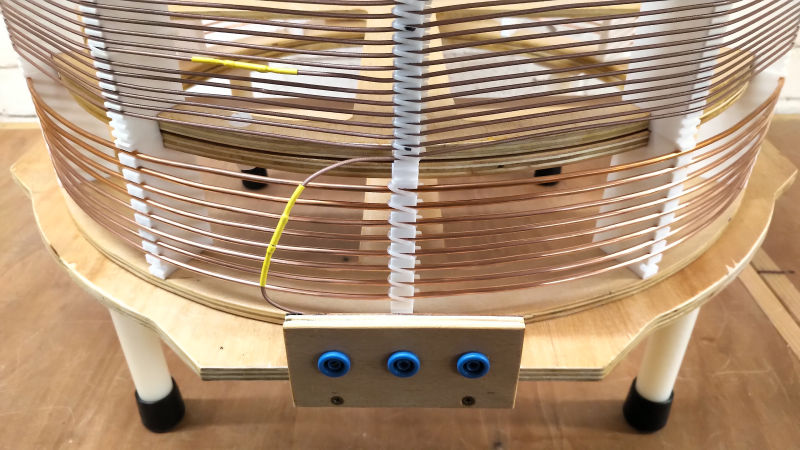
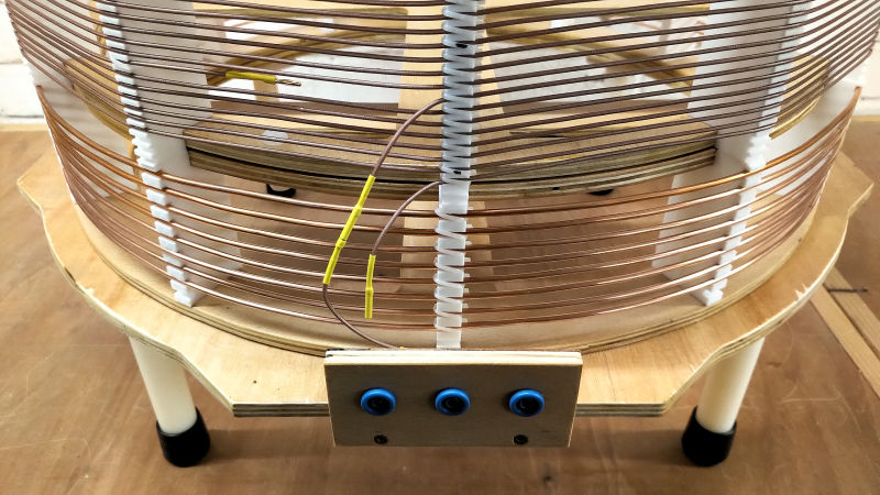
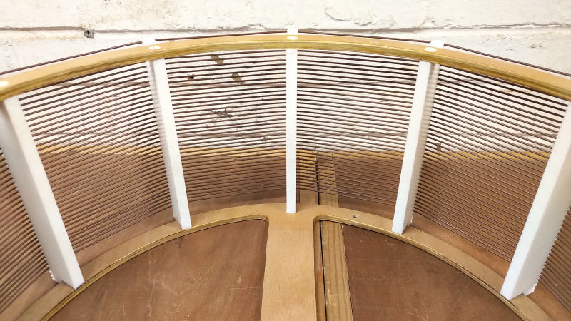
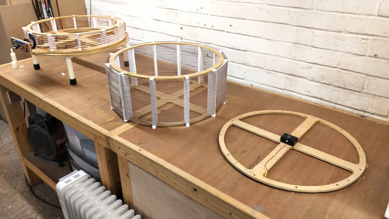
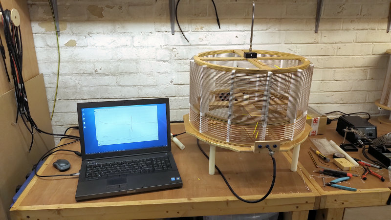
Figures 3 below show some of the construction features of the vertical cylindrical coil design, including the modular coil construction and base, the secondary coil former, mounting, windings and coil frequency configuration, and the primary coil former, windings and configurable turns electrical connections. It is interesting to note that the secondary coil is designed with turns right to the upper end of the former. This construction method allows another secondary to be placed on top of the first, connected with inline 2mm connectors, and with a direct continuation of the windings with the same conductor and turns pitch, and hence making a modular and extensible coil system to address a wide range of different frequency experiments. The system can be extended functionally down to 475kc with a secondary coil only, and even further to lower frequencies when an extra coil design is used. These lower frequency designs and experiments will be reported subsequently on the website, and are mentioned here to give the reader an understanding of the scope and flexibility of the this experimental design.


Small Signal AC Input Impedance Measurements
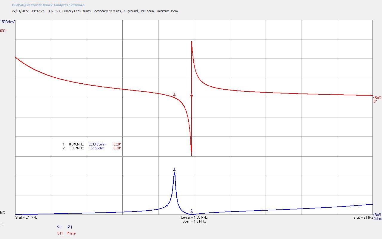
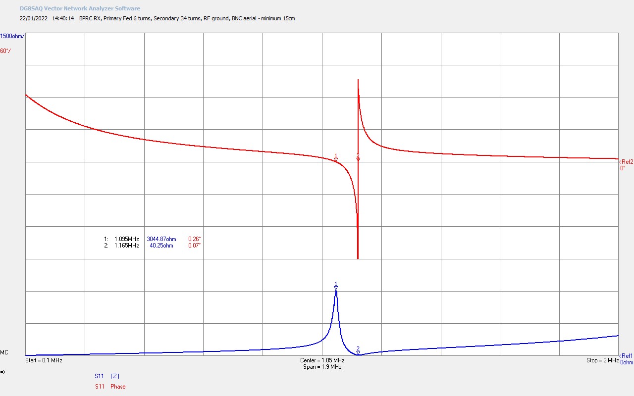
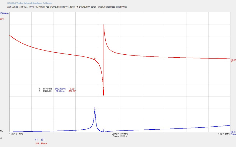
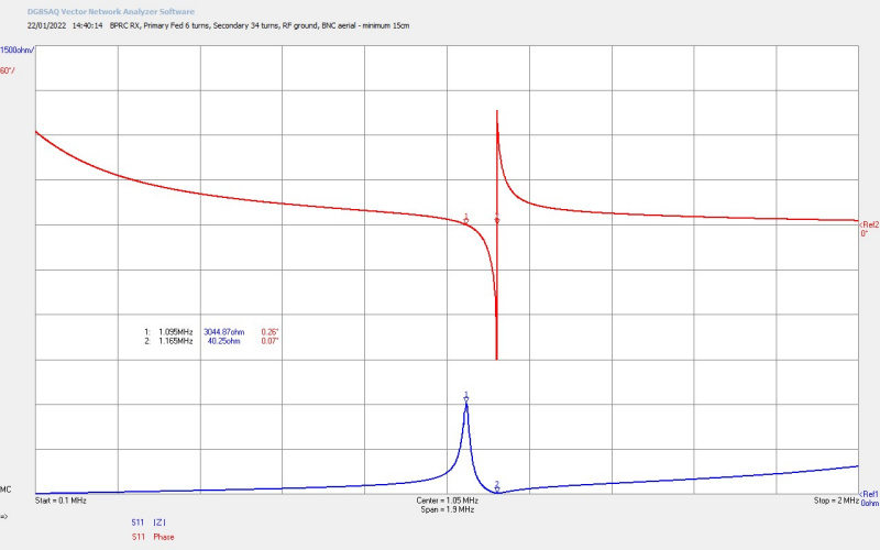
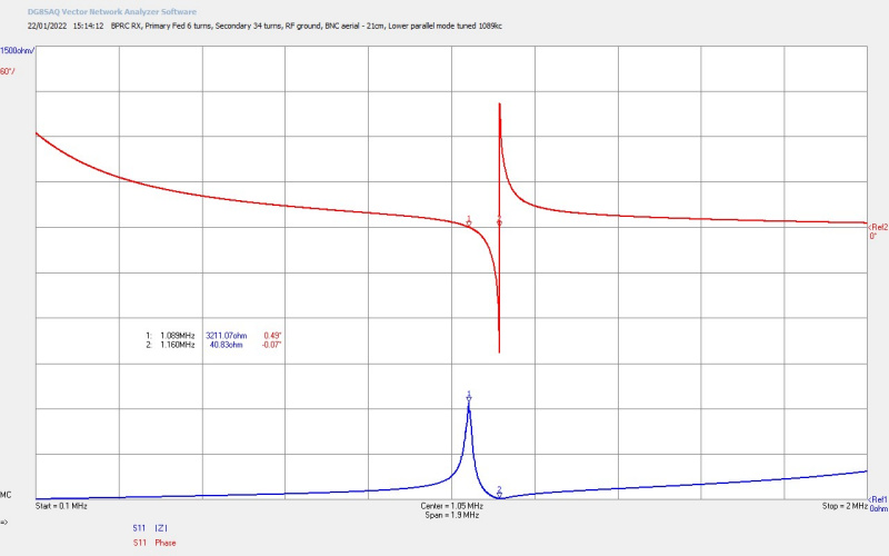
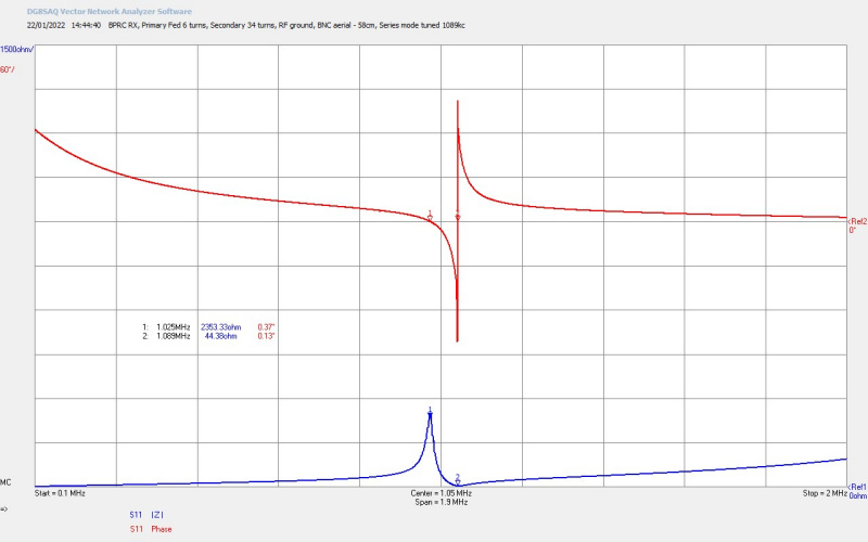
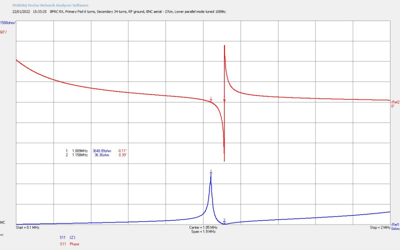
Figures 4 below show the small signal ac input impedance Z11 measured directly on the complete Tesla coil transformer at both 909kc and 1089kc. The transformer was measured with a telescopic aerial at the top-end for fine tuning, and a good RF ground at the bottom-end as would be the case in the field experiments at Brookmans Park. These measurements were made using an SDR-Kits VNWA vector network analyser, as used on many experimental pages on this site.


To view the large images in a new window whilst reading the explanations click on the figure numbers below.
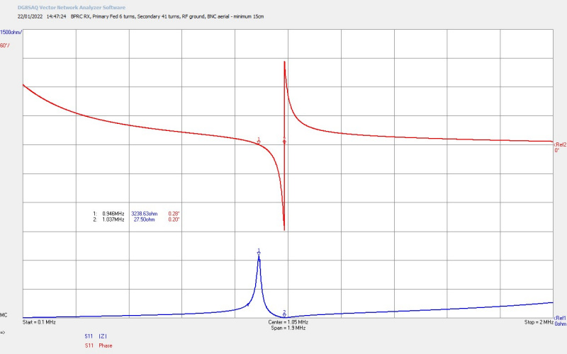
Fig 4.1. Here the secondary coil is configured with 41 turns for 909kc tuning, and the aerial has been set to minimum extension. The parallel mode @ M1 is at 946kc, and the series mode @ M2 is at 1037kc. This is the highest frequency of tune for the 909kc secondary and means that through extension of the telescopic aerial both the parallel and series modes can be tuned to the required frequency. The primary has been set to the optimum 6 number of turns which achieves the best balance between high quality factor of the secondary coil, and magnetic coupling k coefficient between the primary and secondary coils.
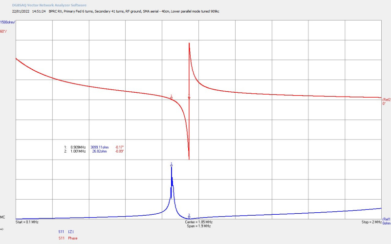
Fig 4.2. The telescopic antenna has been extended to 40cm which increases the wire length at the top-end of the secondary coil, reducing the resonant frequency of both parallel and series modes. Here the parallel mode @ M1 is now correctly tuned to 909kc, and the series mode @ M2 of 1001kc.
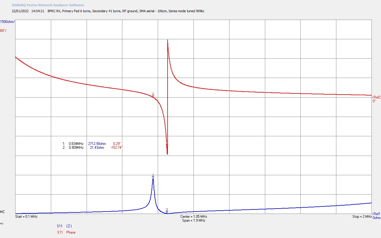
Fig 4.3. With further increase in telescopic aerial extension to 106cm the series resonant mode is now correctly tuned to 909kc and the parallel mode has fallen further @ M1 to 834kc.
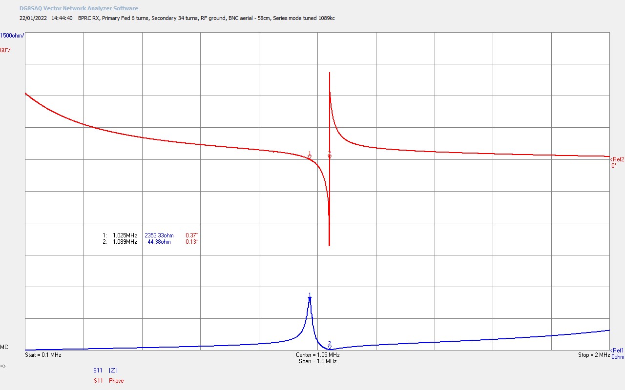
Figs 4.4, 4.5, and 4.6. Show the same process for the 34 turn secondary configured for 1089kc tuning.
Figures 5 below show the small signal ac input impedance Z11 measured directly on the Tesla coil transformer at 1089kc from 1 primary turn up at the full 8 primary turns. All figures are presented on the same vertical and horizontal scales to allow for direct comparison as the number of primary turns increases.
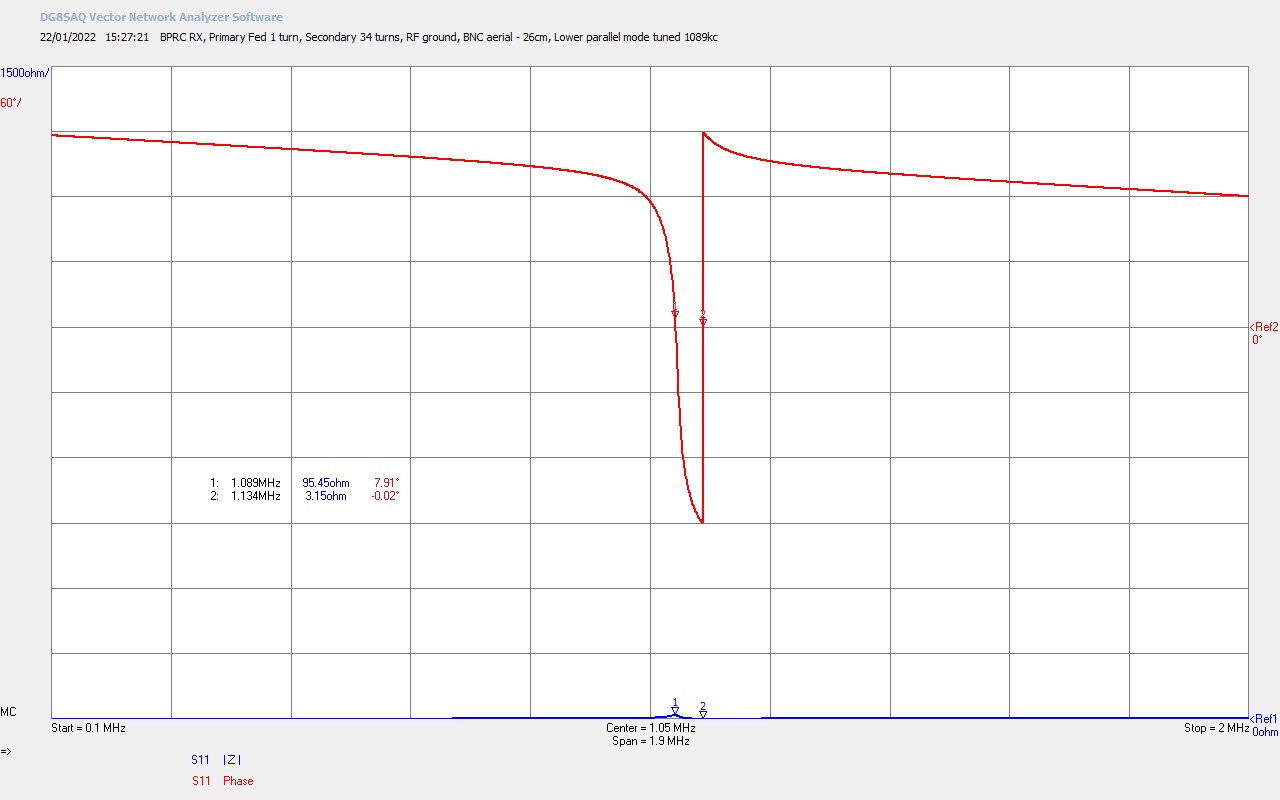
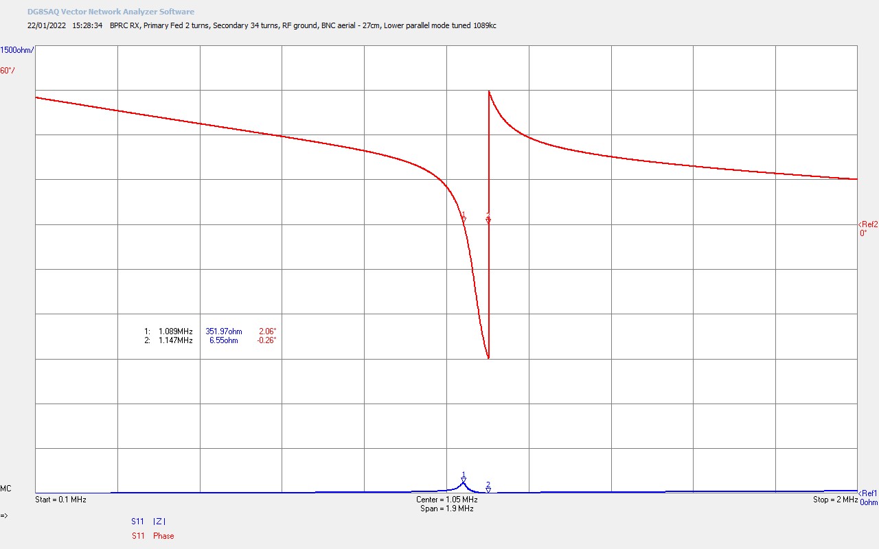
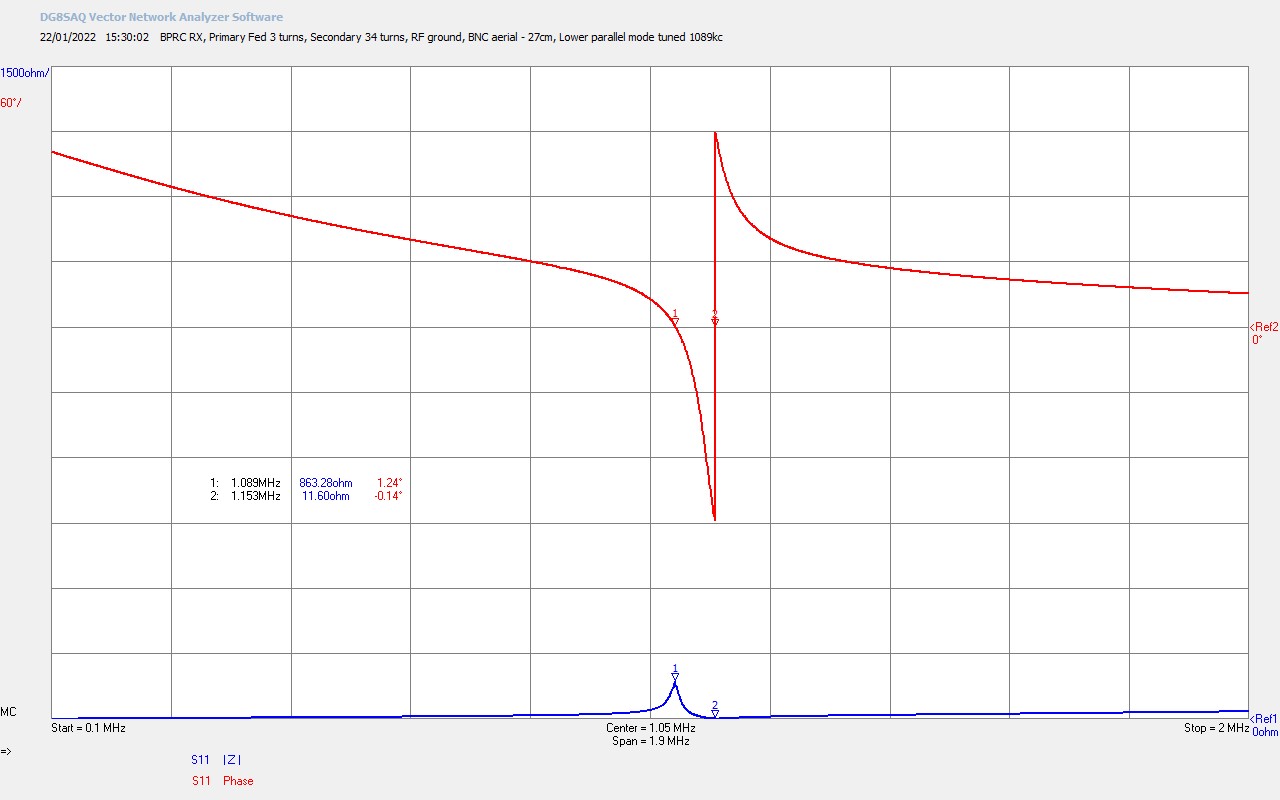
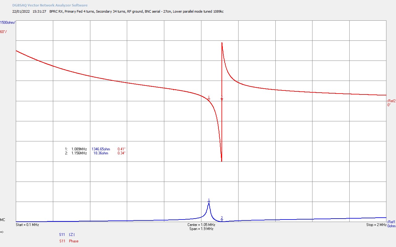
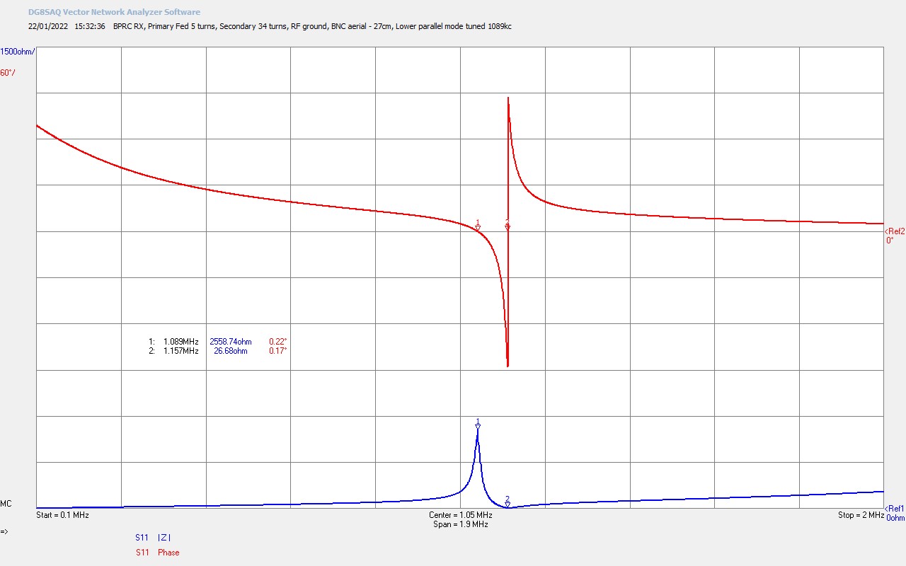

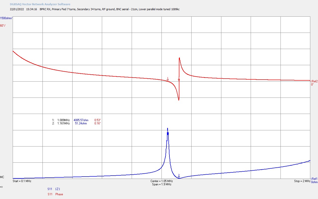
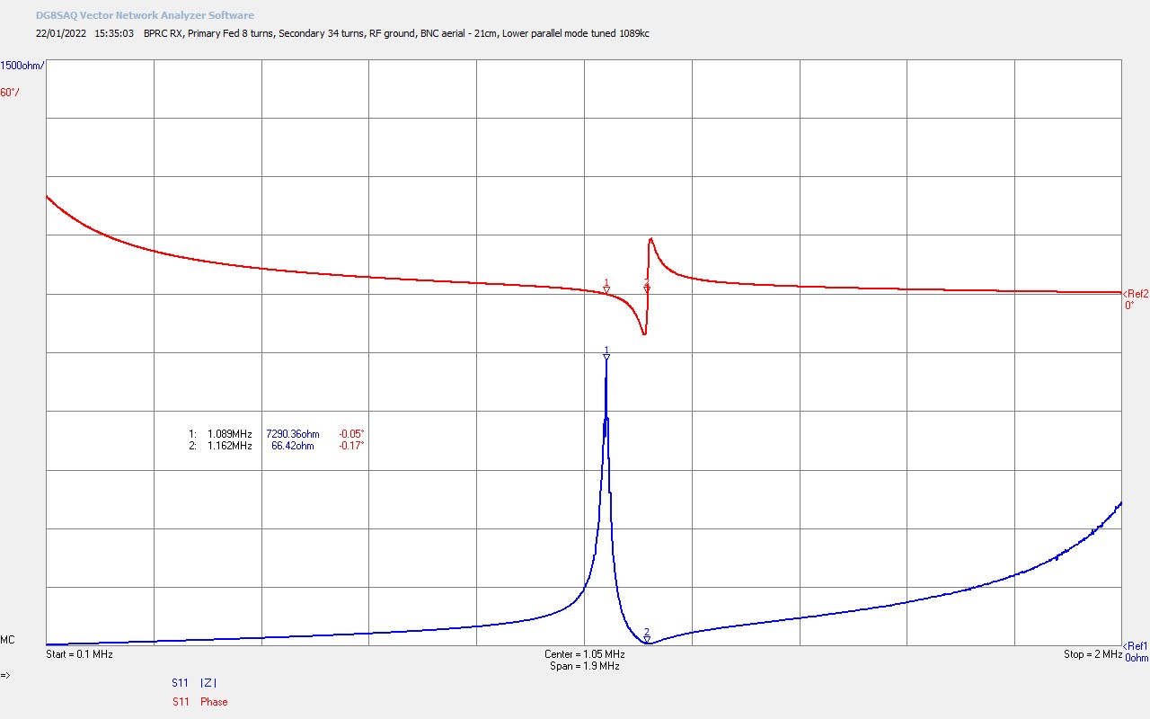
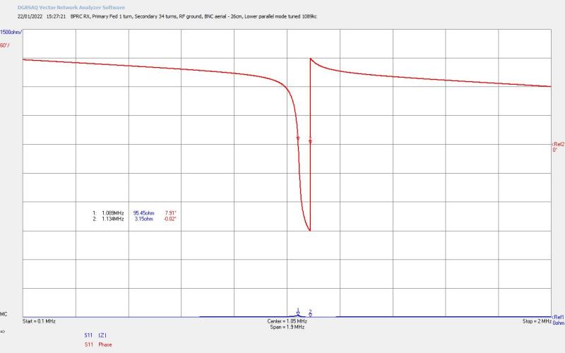
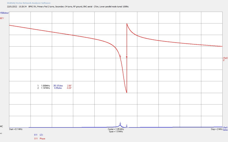
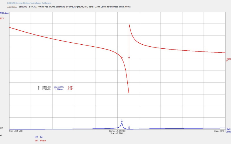
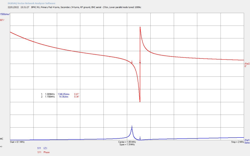
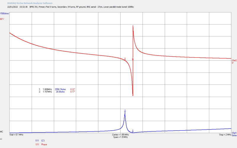
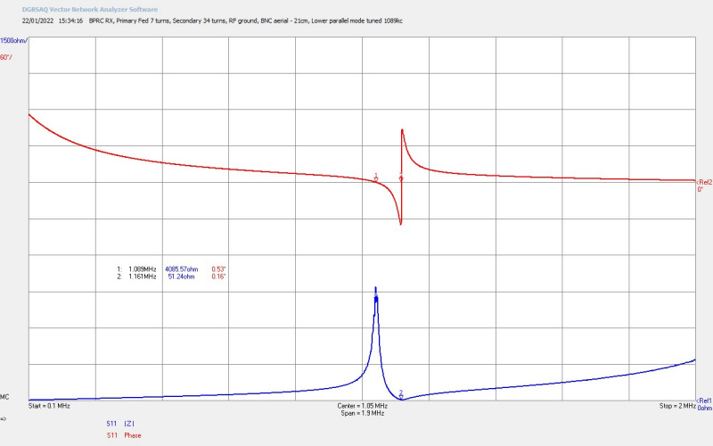

At 1 turn the coupling to the secondary coil is very low, it is under-coupled, which is insufficient to properly develop the parallel and series modes. At 2 turns the coupling has improved a bit but is still insufficient to properly develop the two resonant modes properly. From 3 turns up to 6 turns the coupling increases considerably, and all of these turn taps could be used to operate the Tesla transformer, where 6 turns is the optimum balance between the high quality factor, and hence free resonance of the secondary coil, and optimum coupling to the primary, and hence well developed parallel and series modes transformed into the primary. At 7 and 8 turns the secondary coil is over-coupled with the primary, the Q factor of the secondary is damped down, and the receiver starts to become too dominated by the characteristics of the primary, or tending towards force “driven” by the primary.
Used as a transmitter or receiver coil, 6 turns has been found to be best with this specific cylindrical coil design, in terms of its impedance and coupled characteristics. Where equal weights of copper in the primary and secondary coils is significant to the type of experiment and intended purpose of the system e.g. in a high-efficiency TMT system optimised for the LMD mode, where you achieve the best transformation efficiency and balance of the TEM and LMD modes with the most continuous boundary conditions in the transformer, (equal weights or surface areas of conductor dependent on frequency band of operation). For more details on these boundary conditions and the optimal tuning of a TMT system see the Transference of Electric Power series.
Experimental Results, Considerations, and Conjectures
This experiment demonstrated that ~55mW of power could be received in a Tesla coil transformer, tuned at 909kc at the parallel resonant mode of the coil, when attached to a very good RF ground, and at a distance of 300m from a 150kW broadcast radio transmitter at the same frequency. It was determined by measurement that the telluric wave contributed ~39mW to the total received power, and the radio wave ~16mW of power, showing that more power was received directly through the telluric channel between radio transmitter and the RX coil. The level of received power was sufficient only to light an LED bulb either by the radio-wave on its own (no direct ground connection), or by the telluric and radio-wave combined. It was also noted using two different neon bulbs that no significant tension was established across the secondary coil when connected to either the on-site ground node, or by a ground rod driven into the ground in the same proximity, or by the radio-wave alone when retuned and not connected directly to ground. The presence of very little tension across the secondary coil would makes it impossible to extract any useful power from the Tesla transformer receiver, and the tension of the coil and the level of the received power at 55mW is consistent.
To illustrate what is meant by tension across the Tesla coil secondary let us consider what is necessary to light a 100W light bulb using such a transformer. This experiment can be done on the bench with a generator using a suitable amateur radio exciter or linear amplifier, or a high-power oscillator arranged to oscillate at the correct frequency. The generator is connected in reverse on the Tesla transformer with the ‘hot’ terminal of the generator output connected to the bottom-end of the secondary coil, and the ground terminal connected down to a good RF earth, and is arranged to output 100W of power at the series resonant frequency of the secondary coil. The primary coil is connected only to the two terminals of a 100W incandescent lamp, the number of turns on the primary having been arranged to best match the impedance of the incandescent lamp when fully illuminated for maximum power transfer. There will of course be minor losses in receiving the power in the load through the optimised Tesla transformer, and with careful arrangement these can be < 1%.
With this experiment arranged and operational it can be seen that in a well matched and tuned condition ~ 100W of power from the generator will fully illuminate the incandescent lamp. In this condition a neon lamp will show a strong potential gradient across the windings of the secondary coil, from a maximum at the top-end and to a minimum at the bottom-end. This tension across the secondary coil is easily in the range of kVs, and enough also to draw a small streamer of the top of the secondary coil with a fluorescent bulb or other lower impedance receptacle. So, to light a 100W incandescent lamp, or even for that matter a 5W incandescent lamp, using a Tesla transformer, there will always be a certain tension across the secondary coil. With this established it is clear that the experiment at Brookmans Park, even in close proximity to a very powerful radio transmitter, no significant tension was generated across the secondary coil, either from the induction field from the transmitter, the received radio-wave, or the received telluric-wave. Indeed if that much tension was present then I would expect to get an electric shock or RF burn simply by touching the on-site ground node or earth rod in the experiment. Clearly the quantity of power required for such tension is not being passed through the earth by any transmission mode, and hence was not available for harvesting by the Tesla transformer receiver.
In the telluric experiment Transference of Electric Power – Single Wire vs Telluric ~45mW of power was transferred through a telluric channel 18m point to point between the ground system and connections, with 500W of power supplied to the primary of the transmitter Tesla transformer. It was conjectured that almost all of the transmitter power @ 1860kc was absorbed into the ground at very close proximity to the ground system, and very little of the supplied power was able to reach the receiver Tesla transformer, which also appears to be the case in this Brookmans Park experiment. Even if 1% of the transmitter power escapes the radial ground plane, that is ~1.5kW @ 909kc, and almost all of this is absorbed in the earth, leaving only ~39mW of received power from the telluric-wave 300m from the base of the transmitter antenna. It is conjectured that based on these experiments that 909kc is still far too high a frequency for practical transference of electric power using the telluric-wave. It should also be considered here that the Tesla transformer receiver may need to be arranged so as to “draw” the power through the ground from the transmitter, in a more coherent manner than simply being arranged as a receiver connected to a ground node and tuned to the transmitter frequency. Then it may be that the receiver can be tuned in some other fashion that would enable power to be drawn from the transmitter, and this needs to be investigated further.
The other important consideration is that this experiment is between an antenna optimised for TEM broadcast radio transmission, and a Tesla transformer intended to draw power from the cavity in the LMD mode. In this sense the fundamental design and principle of operation of the TX and RX system is different, and they are intended to work with different configurations and modes of the magnetic and dielectric fields of induction. This may also be a significant reason why so little power could be extracted from close proximity to a powerful transmitter. In effect there is no “cavity” between the TX and RX in this case. In an ideal TMT apparatus, the LMD mode is tuned in the cavity formed between and including the TX and RX secondary coils. When the LMD mode is at its maximum equal tension can be accomplished across both the TX and RX secondary coils, ideally the bottom end of each coil is at zero potential, the point of maximum current into the ground system and transmission channel, and one or more potential nulls or zero points form along the length of the transmission medium. Hence the LMD mode is established across the cavity and electrical energy is passed back and forth across the cavity in a way very similar to light in a laser cavity. Tuned correctly the LMD mode can transfer considerable power between the TX and RX coils across the cavity, and at very high efficiencies over 99%. More details and practical experiment and demonstration of this can be found in High-Efficiency Transference of Electric Power – 11m Single Wire and High-Efficiency Transference of Electric Power posts.
So in this experiment where the generator and TX coil is a TEM broadcast radio station, we do not have a TMT arrangement with a tuned cavity between TX and RX, optimised for the LMD transmission mode, and hence we would not expect to achieve high-efficiency transference of electric power in this arrangement. It maybe that with adjustment of the RX coil it may be able to “draw” more power from the earth, but I would anticipate this also to be at a much lower frequency where less of the RF power is absorbed around the transmitter ground system. The radio transmitter is after all designed to minimise the power loss from its ground system, and maximise the power supplied to the TEM transmission mode via the ground-wave.
Conclusions and Next Steps
In summary conclusions, the very low power received in close proximity to a very high power radio transmitter is conjectured to be as a result of the following:
1. Mismatched transmission modes of the TX (TEM) and RX (LMD), where there is no tuned cavity formed between the two in the telluric channel as there would be in a complete TMT system.
2. The frequency of the transmitter at 909kc leads to very high power absorption losses in the earth close around the transmitter ground system, resulting in very little transferred power through the ground up to one wavelength from the transmitter base.
3. The tension or “pressure” exerted on the Tesla transformer receiver coil was very low even when connected to a substantial on-site ground node, and hence only ~55mW could be transformed into the primary circuit at the receiver. The available electrical energy at the on-site ground node was insufficient to be detected by human contact.
4. The telluric-wave was measured as larger by a factor of 3 than the radio-wave received at one wavelength using the Tesla transformer, which appears surprising when the RX coil is still within the induction field of the transmitter antenna.
The design of the Tesla transformer receiver used in this experiment is a direct tuned secondary coil which does not include in itself a third resonant coil, Tesla’s extra coil, which changes the characteristics of the transformer in a number of important ways. The characteristics of Tesla’s extra coil will be discussed and demonstrated in subsequent posts on this site. Next steps to the experiment presented would include a three-coil receiver design “properly proportioned”, and tuned to work with the Brookmans Park radio transmitter, which may produce a different result and be able to “receive”, “draw” or “extract” more power in accordance with what was at least theoretically expected in the crystal radio initiative.
Click here to continue to the next part, looking at Telluric Transference of Electric Power – MF Band 27-70 Miles.
1. Caras, L., A History of Brookmans Park Transmitting Station, 1982, North Mymms History Project
2. Gutteridge, P., Brookmans Park – Pictures and Memories, 1974, BBCeng.info
3. Pennington, A., Brookmans Park – A Brief History, 2013, British DX Club
4. Wikipedia. Brookmans Park Transmitting Station, Wikimedia Foundation Inc., Wikipedia, 2022.
5. Dollard, E. and Forum Members, Eric Dollard Official Forum -> The Crystal Radio Initiative, Energetic Forum, 2012.
6. Dollard, E. and Energetic Forum Members, Energetic Forum, 2008 onwards.
7. A & P Electronic Media, AMInnovations by Adrian Marsh, 2019, EMediaPress
Telluric Transference of Electric Power – MF Band 2-8 Miles
This experimental post is a follow-on from the Telluric experiment presented in Transference of Electric Power – Single Wire vs Telluric. In that previous experiment a Tesla Magnifying Transformer (TMT) apparatus, consisting of TX and RX cylindrical Tesla coils, were connected together via a 18m point-to-point telluric transmission medium, and with ground connection cables 26m in total between TX and RX secondary coils. In the medium-frequency band (MF) at 1.86Mc, in the mid-field region, 500W input power to the TX coil generated ~ 80mW of output power at the RX coil, from a combination of the telluric-wave and radio-wave. In this new experiment the same TMT apparatus and generator is used, and the telluric transmission medium is extended into the close far-field region at 2 and 8 mile field locations from the TX coil. In both locations natural water features were used as the telluric ground connection for the RX coil, and the transmitted signal could be clearly received, and was shown to result from the combination of a telluric-wave component through the ground, and a radio-wave component above ground. It is conjectured that at the 2 mile location the longitudinal magneto-dielectric (LMD) transmission mode was dominant in the telluric cavity between TX and RX, and the transverse electromagnetic (TEM) mode was dominant at the 8 mile location.
The video experiment demonstrates and includes aspects of the following:
1. Portable Tesla receiver (RX) setup and tuning, using a cylindrical coil tuned in the 160m amateur radio band, for radio-wave and telluric-wave field experiments in the close far-field region.
2. Telluric ground connection using a submerged aluminium metal plate, firstly in a natural lake connected to a river 2 miles from the lab transmitter (TX), and secondly in a man-made reservoir 8 miles from the TX.
3. Small signal ac impedance measurements using a vector network analyser to tune the RX Tesla coil to the series and parallel resonant modes.
4. Fine tuning to different modes, and optimal received signal strength at 1.86Mc, using a telescopic aerial at the top-end of the RX secondary coil.
5. Comparison of radio-wave and telluric-wave measurement by re-tuning the RX coil from the Telluric ground plate connection, to an ungrounded single wire bottom-end extension.
6. At both 2 and 8 miles the CW audio tone could be received and heard at only 10W TX input power.
7. At 2 miles, 6 bars of signal strength were measured at 10W TX power at 1.86Mc for the telluric-wave and radio-wave combined, and 1 bar for the radio-wave only.
8. At 8 miles, 4 bars of signal strength were measured at 400W TX power at 1.86Mc for the telluric-wave and radio-wave combined, and 2 bars for the radio-wave only.
9. The lower parallel resonant mode of the RX Tesla coil was found to receive the maximum signal strength at both 2 and 8 miles.
10. The lower parallel resonant mode was found to be much more sensitive to body and object proximity than the series resonant mode.
11. It is conjectured that at the 2 mile location the longitudinal magneto-dielectric (LMD) transmission mode was dominant in the telluric cavity between TX and RX, and the transverse electromagnetic (TEM) mode was dominant at the 8 mile location.
Video Viewing Note: In the video the telluric-wave (in the ground) is referred to as the ground-wave, and the radio-wave (over the ground) is referred to as the sky-wave, and not to be confused with the amateur radio definitions of ground and sky wave.
The experimental apparatus, generator and operation, and the TX ground system, is exactly the same as that used in Transference of Electric Power – Single Wire vs Telluric, and is discussed and presented in detail, along with the full experiment schematic, in that post. Operation of the generator in this field experiments is via a research colleague at the lab, and setup, tuning, and operation of the generator can be viewed in detail in the single-wire experiment video presented in the aforementioned post.
A key measurement in the telluric experiments which needs some consideration is the process of measuring the radio-wave of a radio transmission. For all radio transmission, and as transmitters are almost always grounded down to earth, the major component of the transmission is the propagating TEM wave from the radio transmitter antenna to the receiver antenna. In relation to a telluric experiment, we cannot assume that all the power transferred from the TX to the RX coil is via the telluric channel through the ground, as there will also be a radio-wave component at the receiver. We also cannot simply remove the bottom-end ground connection of the RX coil to measure this radio-wave component, as this will change the wire-length of the secondary cavity, and hence change its fundamental series resonant frequency, and any connected receiver which is tuned to the transmitter frequency will erroneously show no received signal, simply because the RX coil is not correctly tuned to the transmit frequency.
To accomplish the radio-wave part of the experiment, and as demonstrated in the video experiment, the telluric ground connection is removed from the RX coil, and is replaced with a single wire 10m in length which is NOT connected into the ground or to any other grounded end-point. The telescopic aerial at the top-end of the RX coil is now fine adjusted so that the series mode resonant frequency of the RX coil matches the transmit frequency. This is accomplished by maximising the received signal at the receiver at the correct TX frequency, and then cross checked by VNWA measurement to confirm correct tuning of the RX coil. In this way the RX coil is now tuned to the correct frequency for receiving the transmitted signal, but is also not connected into the ground.
The signal strength now received on the radio receiver, or power meter, is a result of the radio-wave contribution only, and is less than the combined radio-wave and telluric-wave, as can be seen in the video experiment. The proportion of radio to telluric wave can also give a good indication as to the dominant transmission mode involved in the transference of electric power between TX and RX coil. Equal radio and telluric components tend towards a dominant TEM mode of propagation between the two, or with a combination of TEM and LMD, with the TEM mode dominant. A much larger telluric wave can indicate a dominant LMD mode, and this is demonstrated at the 2 mile field location.
Small Signal AC Input Impedance Measurements
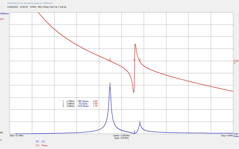
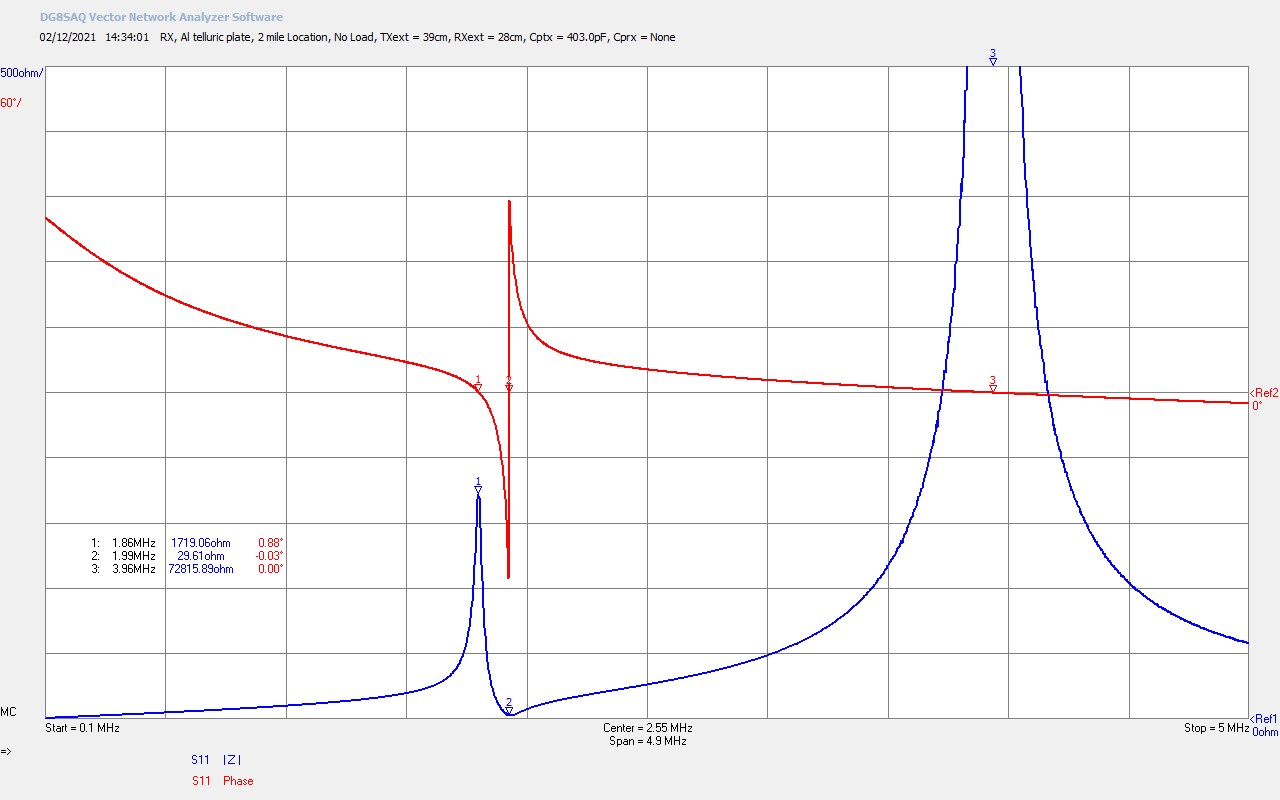
Figures 2 below show the small signal ac input impedance Z11 measured directly on the RX coil of the TMT system, and using an SDR-Kits VNWA vector network analyser, as used on many experimental pages on this site.
To view the large images in a new window whilst reading the explanations click on the figure numbers below.
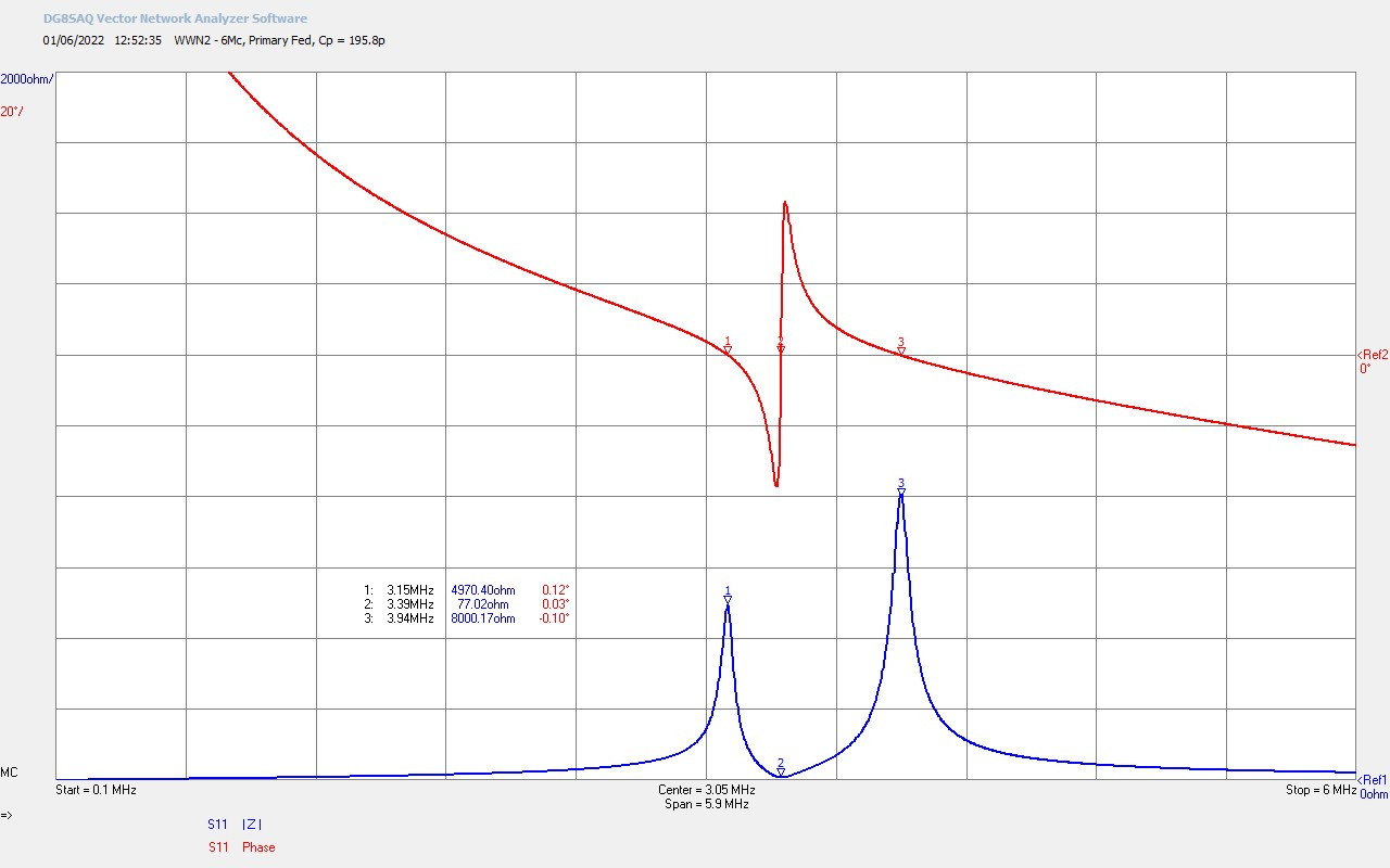
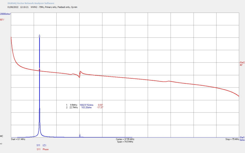
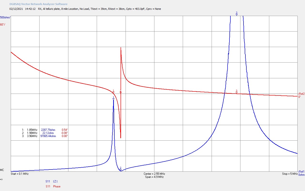
Fig 2.1. Shows the small signal ac input impedance Z11 of the RX cylindrical Tesla coil, connected via the aluminium grounding plate submerged in a natural river-fed lake at the 2 mile location. The grounding plate is connected to the bottom-end of the RX secondary coil via an 8m 6AWG micro-stranded, silicone coated cable. The RX coil was tuned by adjusting the length of the secondary top-end telescopic aerial, as shown in the video, and in this measurement shows tuning to the lower parallel mode, (in this case the parallel mode of the secondary coil), at ƒL = 1.86Mc @ M1. The RX coil is setup without using balanced parallel modes, as with very small signal reception experiments the additional capacitive loading appears to reduce the amplitude of the measured signal via the Sony ICF-2001D radio receiver. At ƒL the input impedance, (output impedance presented to the radio receiver), is RL ~ 1719Ω. The higher impedance of the lower parallel mode is more suited than the low impedance of the series mode, to directly feeding the Sony radio AM external antenna input, and hence the input impedance of the super-heterodyne first stage receiver in the Sony. Maximum signal reception results were consistently accomplished in the field using the lower parallel mode tuned to the transmit frequency of 1.86Mc.
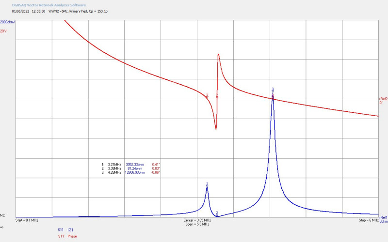
The fundamental series resonant mode here occurs at ƒO = 1.99Mc @ M2, and again can also be tuned to 1.86Mc by longer extension of the telescopic-aerial. A comparison of the receiver measurements were made in the video against the lower parallel and series modes, and it was determined that the lower parallel mode produced the best results for measurement with the Sony radio receiver, and the series mode would be better for direct power measurements using the HP435B with HP8481H thermocouple power sensor which has a 50Ω input impedance. For the most accurate direct power measurements the output of the RX coil should ideally be matched to the 50Ω input impedance of the sensor, ensuring maximum power transfer from the RX receiver coil to the HP power measurement system. If and when higher powers can be measured using direct power measurement, then a 2:1 current balun would be suitable to affect quite a good match between the RX coil primary output RS ~ 29.6Ω, and the HP power sensor at 50Ω. The upper parallel mode ƒU = 3.96Mc @ M3 originating from the primary coil, cannot be used in this particular experiment as it cannot be tuned down sufficiently low to 1.86Mc using either additional wire length (lowering the series mode), or loading the RX primary coil directly with parallel capacitance.
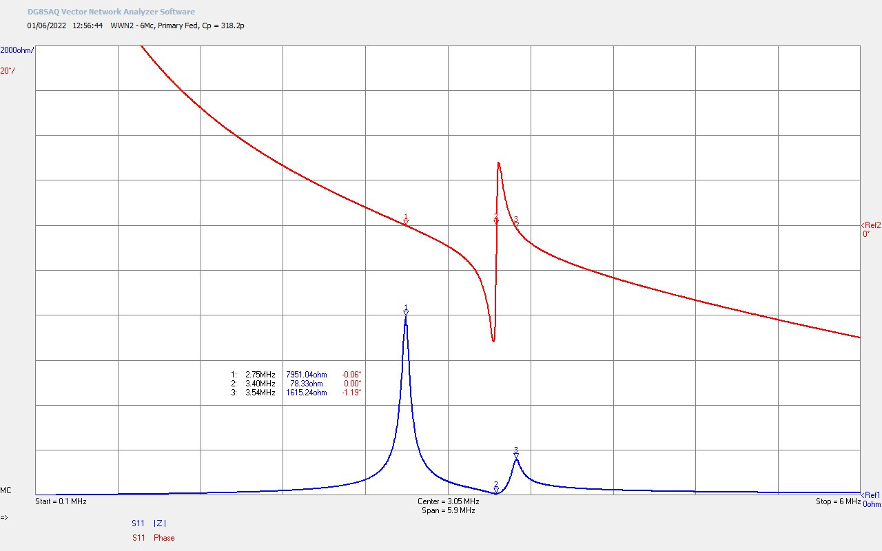
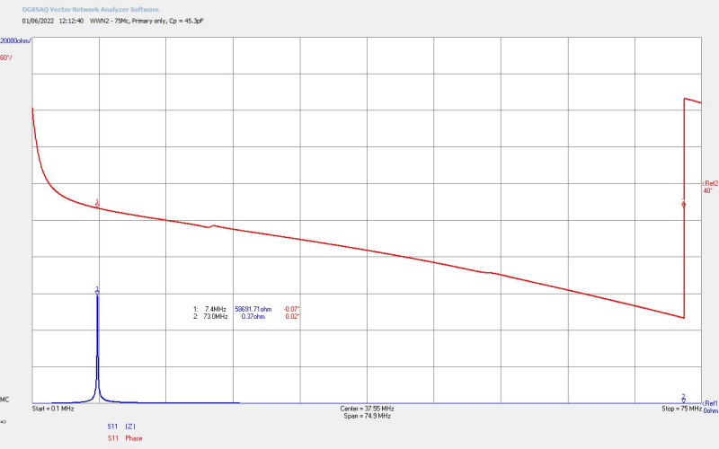
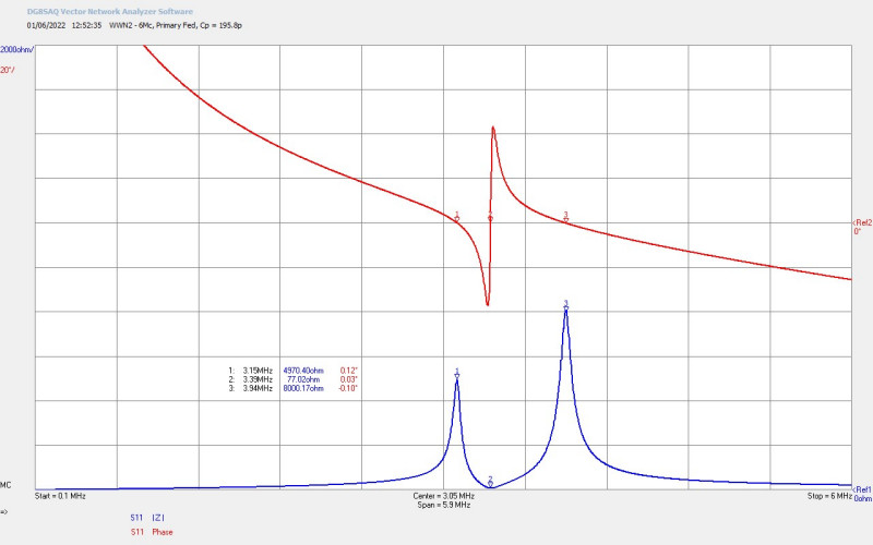
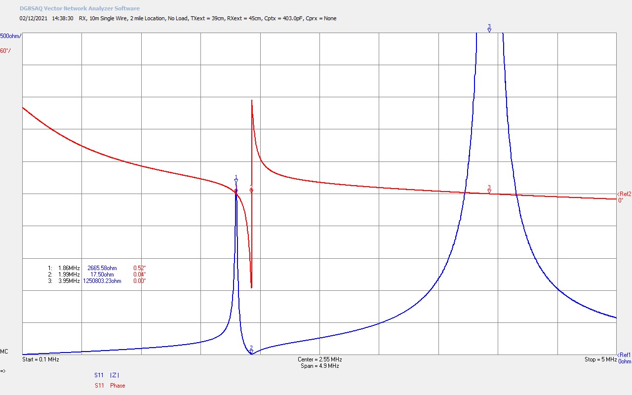
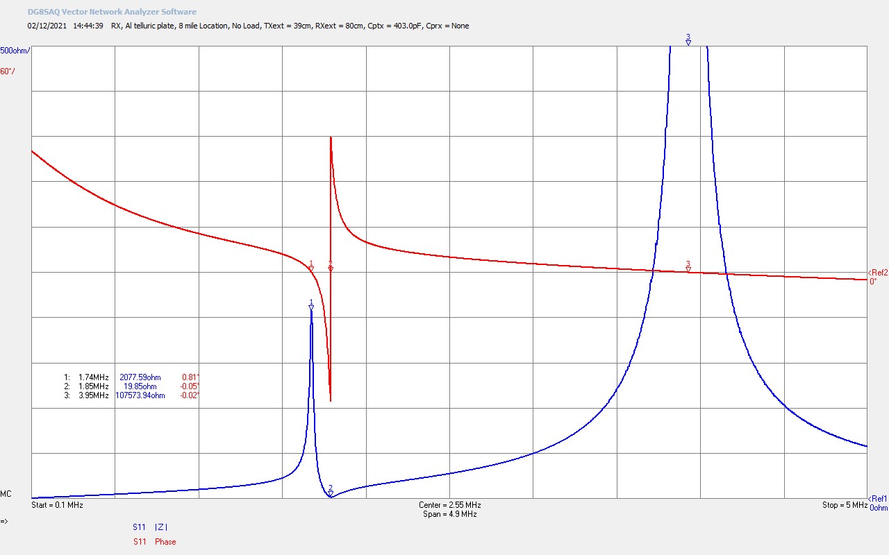
Fig 2.2. Here the RX coil at the 2 mile location has been tuned to the lower parallel mode ƒL = 1.86Mc @ M1 with the 10m ungrounded single wire at the bottom-end of the secondary coil, and adjustment of the wire-length of the secondary via the telescopic aerial length from 39cm to 45cm. The Q of the RX coil is noticeably higher from being ungrounded and the lower parallel resonant mode impedance is higher at RL ~ 2666Ω. The series resonant mode ƒS = 1.99Mc @ M2 is slightly stronger, and has a lower impedance RL ~ 17.5Ω. Otherwise the characteristics are very similar to when the aluminium telluric ground is being used. This tuned characteristic using the 10m ungrounded single wire was used to measure the radio-wave component of the received signal, which at the 2 mile location, was much lower than the telluric-wave component.
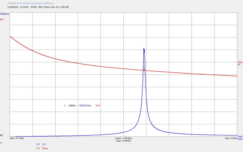
Fig 2.3. Shows Z11 of the RX coil connected via the aluminium grounding plate submerged in a reservoir at the 8 mile location. The parallel mode is here tuned to 1.85Mc rather than 1.86Mc, and there is a consistent 1Hz tuned error throughout this experiment at the 8 mile location. When checked the 1Hz difference did not make a discernible difference to the received signal strength or reception at the field location when using either the lower parallel or series resonant modes. It is interesting to note that the Q of the RX coil system is higher at the 8 mile location, and is more similar to the 10m single wire result in fig. 2.2, than the telluric-plate result in fig. 2.1. It could be considered that this may indicate that the telluric connection to the earth was not as good at the 8 mile location, something which was certainly reflected in the much reduced received signal strength measurements.
Fig 2.4. Here the series mode is now tuned at 1.85Mc, and it is interesting to note that the series mode impedance is again not much higher than that for the 10m single wire results in fig. 2.2, again suggesting that the telluric connection is not as good at the 8 mile location. So both the lower parallel mode and the series mode are closer here to the 10m single wire results achieved at the 2 mile location, and that may suggest that the 8 mile location was more suited to reception of the radio-wave, and less to the telluric-wave. This was indeed what was measured, that the telluric-wave and radio-wave contributed almost equally to the received signal strength at this location, and a lot of transmitter power was needed to get a well-defined signal strength measurement.
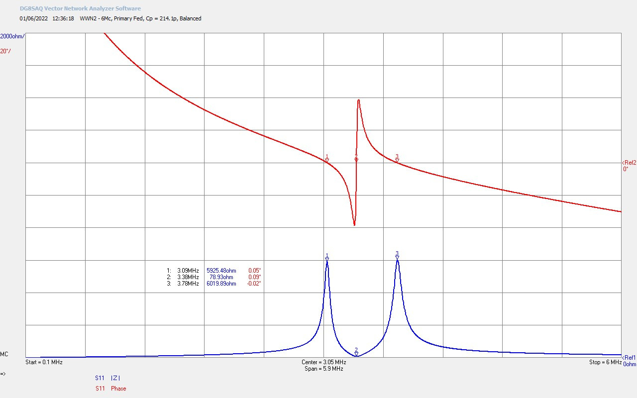
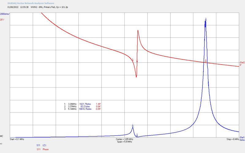
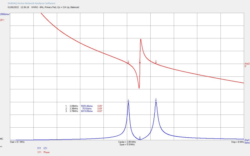
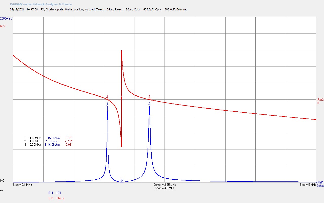
Fig 2.5. Shows the balanced mode of the RX coil, and with the series resonant mode tuned to the transmitter frequency. Note that for clarity the magnitude of the impedance scale, |Z| (blue) has been increased from the previous 500Ω/div to 2000Ω/div. The parallel modes from the primary and secondary coil were balanced using a primary loading capacitance of CPRX = 282pF, and this balanced condition in a TMT has been shown to be beneficial to achieving a very high transfer efficiency in single wire mid-field region experiments in the High-Efficiency Transference of Electric Power series. In this telluric experiment, in the far-field region, this balanced condition was found to introduce too much loading in the RX coil given the very small signals being received, which led to reduced signal strength measurements.
The capacitive loading in the primary coil was removed, and appears sub-optimal for these types of very low power level telluric reception measurements. If and when higher power can be transferred via the telluric transmission medium, the balanced mode may be necessary to maximise the LMD transmission mode, and hence the received telluric-wave. It should be noted that the TX coil is tuned and driven by the generator at its series fundamental resonant mode at 1.86Mc, and with the lower and upper parallel modes balanced using primary capacitive loading CPTX = 403pF, which was found consistently to be the most efficient setup for the TX coil and linear amplifier generator, used in both in this telluric experiment and the experiments presented in Transference of Electric Power – Single Wire vs Telluric.
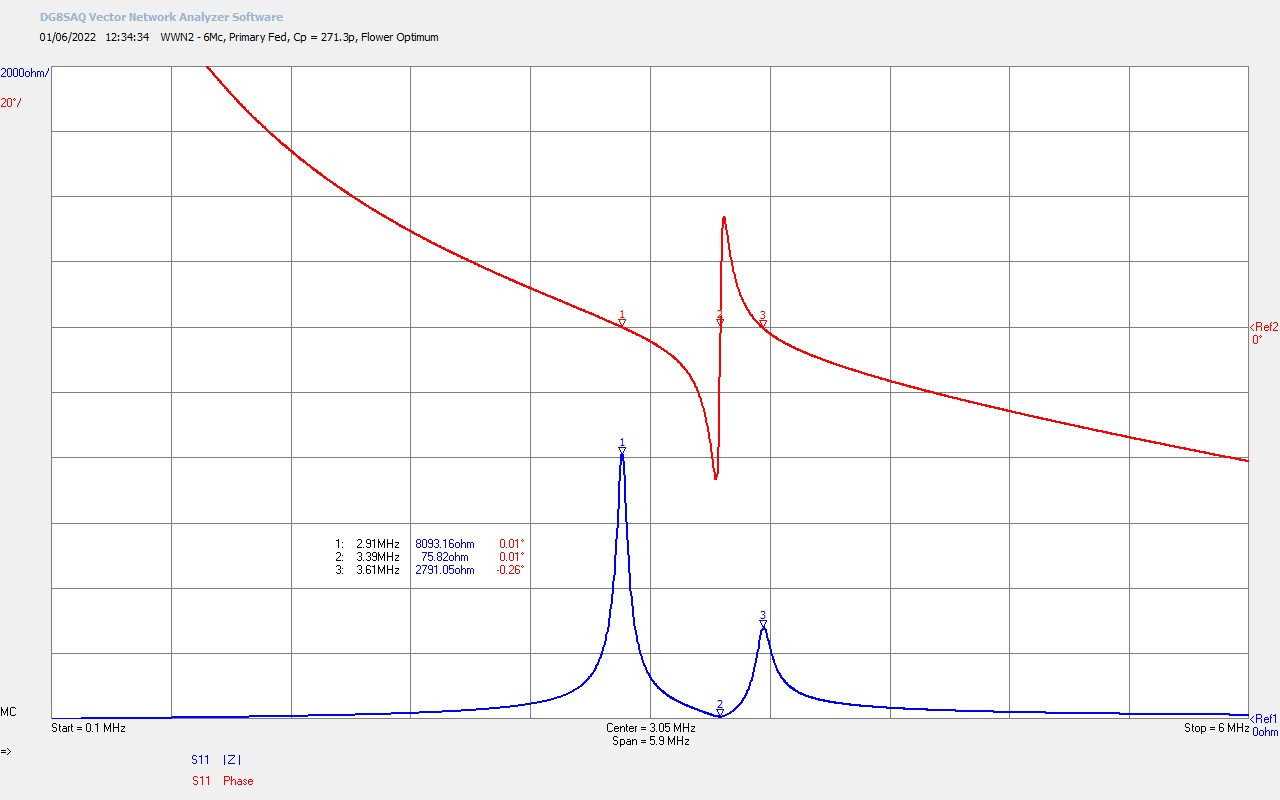
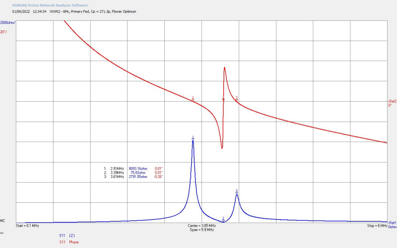
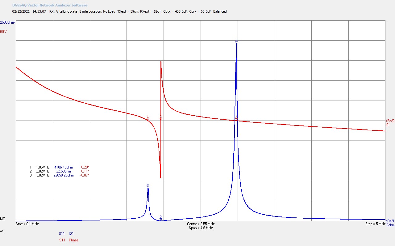
Fig 2.6. Here it was tested to see the maximum balance that could be accomplished between the upper and lower parallel modes, and whilst keeping the lower parallel mode tuned to the transmitter frequency. This characteristic was tuned using a primary loading capacitance of CPRX = 60pF, a significant reduction in loading capacitance from the full balanced mode in fig. 2.5. This produced better signal strength results than the full balanced mode, but still not as good as the unloaded results with no additional primary tuning capacitor. At these very low reception powers it was concluded that the balanced mode simply attenuates the signal too much, and especially in the case were the telluric-wave is not very strong, and the LMD mode is not dominant.
Telluric Transmission in the High MF Band Far-Field
In the first field location 2 miles from the transmitter it was possible to clearly receive with 6 bars of signal strength at only 10W TX power at 1.86Mc for the telluric-wave and radio-wave combined, and 1 bar for the radio-wave only. The attenuation of the signal at 1.86Mc under the ground appears enormous, and it was considered in the previous experiment Transference of Electric Power – Single Wire vs Telluric that this loss is dominated by absorption of the transmitter power by the earth directly surrounding the main telluric ground system in the high medium-frequency band. In the previous experiment only 18m from this telluric ground system the measured power had already dropped from 10W TX power to 1.25mW at the RX coil.
So transmitted power in the earth surrounding the telluric ground system has already reduced by almost 4 orders of magnitude even before it is only 10s of meters away from the ground system connection. When we consider the result achieved 2 miles away the power would have dropped into the micro-watt level to produce the kind of signal strength received by the Sony radio receiver, and so we can conjecture that the transmission over the 2 miles was actually more efficient, than the transmission from the TX secondary coil through the ground system and over the distance of a few 10s of metres. This may also imply that there is very considerable power losses in the interface between the copper of the ground system and the earth, and even with significant water irrigation of the ground system, and relatively low measured impedance at the transmitter frequency.
It is very interesting in the 2 mile location that there was also a large difference in the received combined telluric and radio-wave at 6 bars, and the radio-wave at 1 bar, where in both cases the RX coil was tuned at the lower parallel mode to the transmitter frequency through adjustment of the coil wire length. Again in the previous 18m telluric experiment the proportion of telluric-wave to radio-wave at 10W was 0.7 mW : 0.55 mW, where both components are much closer and contributing approximately equally to the transmission of power from TX to RX, with only slight emphasis on the telluric-wave. In the 2 mile field location the ratio of signal strength telluric to radio is 5 : 1 which we can also conjecture may result from a more dominant LMD mode across the telluric cavity formed by the TMT system.
We do also need to consider the possibility that the radio-wave encountered significant obstacles in the 2 mile TEM propagation, reducing significantly the radio-wave component at the RX coil, but I would suggest that the combination of the two results regarding the better power transmission efficiency over the 2 miles distance than the 18m distance, the relatively close far-field distance, and the large signal strength ratio 5 : 1, could point towards a dominant LMD mode, and a preferential telluric transmission channel, over and above the TEM mode radio propagation channel.
In contrast at the 8 mile man-made reservoir location, although the signal tone could just be detected at 10W TX power, it was necessary to use up to 400W of TX power to get reasonable signal strength up to 4 bars. It was also noted that the ratio of telluric to radio-wave components was again around 1 : 1, and the far-field transmission distance had not significantly increased by going up to 8 miles at the transmitter frequency at the top-end of the MF band. It is considered here that the telluric channel/connection at the RX coil end was not as good as for 2 mile case, and especially in taking into account that the water-body used for the telluric ground was both man-made and may not be so well connected to the earth’s aquatic system. It is conjectured that the LMD mode was not established as dominant in the TMT transmission cavity, and that power reception at 8 miles was dominated by the TEM mode of far-field radio-wave propagation.
It must also be considered that the two field locations presented so far were not selected for any special water-table, river inter-connection, underground aquatic properties or channels, or for specific earth and rock type and composition. Both locations are in limestone regions and both are connected to water bodies, the 2 mile location being a natural river-fed lake, relatively close to the underground source of the river (a further 2 miles, so approximately 4 miles to the river source from the transmitter). The 8 mile location, being a man-made reservoir with a river tributary feed and outlet, is a further extension in the same direction from the transmitter. So the 8 mile location is essentially 6 miles further on from the 2 mile location, and 4 miles further on from the natural river-source of the 2 mile location.
Summary Conclusions and Next Steps
In this post, telluric transference of electric power has been explored and demonstrated in two different field locations in the near far-field region from the transmitter at 1.86Mc in the high MF-Band. In both field locations signal strength could be measured at the transmit frequency in both the telluric-wave and the radio-wave at only 10W generator power. There was a vast difference in power required in each location to achieve approximately the same measured signal strength readings, 10W TX power with 6 bars at 2 miles, and 400W with 4 bars at 8 miles, with all other aspects of the TMT apparatus kept constant other than the field location telluric ground connection, and the over-ground terrain profile between the TX and RX. From the experimental results and measurements presented the following observations, considerations and conjectures are made:
1. The LMD mode is conjectured to be dominant in the 2 mile location based on the the large ratio between the measured telluric-wave and the radio-wave, and on considerations on telluric channel/cavity losses both for this experiment, and the previously considered 18m telluric channel.
2. The TEM mode is conjectured to be dominant in the 8 mile location based on the equal ratio of the measured telluric-wave and the radio-wave, and the large input power of 400W needed to get adequate measured signal strength, and on comparison with the very similar telluric experiment results in the 18m telluric channel.
3. The telluric connection quality to the earth through the type of water-body, is conjectured to be the most likely difference between the very different results of the two field locations. The difference in distance of 6 miles is not considered to be the major factor in the large difference in the location results.
4. The underground water inter-connection between the TX and RX is considered to have a significant impact on the quality of the telluric transmission medium between the two ground systems.
5. The impact of the earth soil and rock type and composition is as yet unknown on the telluric channel quality.
6. High losses will occur in the ground system to earth interface, and the telluric transmission channel/cavity with higher transmitter frequencies in the MF band. 1.86Mc appears far too high for any significant power transfer by the LMD mode in a telluric cavity.
7. Telluric transmission via the LMD mode is conjectured to be more efficient than by the TEM mode, and that with a sufficiently low frequency and a properly arranged LMD cavity in the TMT apparatus, it may be possible to transfer larger quantities of power in the far-field with better efficiency than could be accomplished using an overground wireless mode or radio-wave.
Next steps are to further explore Telluric Transference of Electric Power at different field locations both in the close far-field, and then at further distances from the transmitter, both at the same presented high MF-band frequency of 1.86Mc, and then at lower frequencies, and ultimately if possible down into the LF-band where Tesla was working with his own experiments. Lower frequency experiments present considerable challenges, including TMT size and scale, generator type and compatibility, radio regulation and licensing, availability of field locations, and resourcing and funding. If these challenges can be overcome then it may be possible to finally confirm or refute the possibility of high-efficiency telluric transference of power, and understand in much greater detail and accuracy the legacy that Tesla has left us to explore.
Click here to continue to the next part, looking at Telluric Transference of Electric Power – Brookmans Park AM Radio Transmitter.
1. A & P Electronic Media, AMInnovations by Adrian Marsh, 2019, EMediaPress
2. Dollard, E. and Energetic Forum Members, Energetic Forum, 2008 onwards.