


In the early days of my research, and before we built the spark gap generator, it was unclear to me which parts of the electrical system were most directly responsible for generating unusual electrical phenomena, whether it be the generator or high voltage source, the types and arrangements of the various coils, or a combination of these elements setup and arranged in a specific manner, tuned in a specific way, and operated in a specific method.
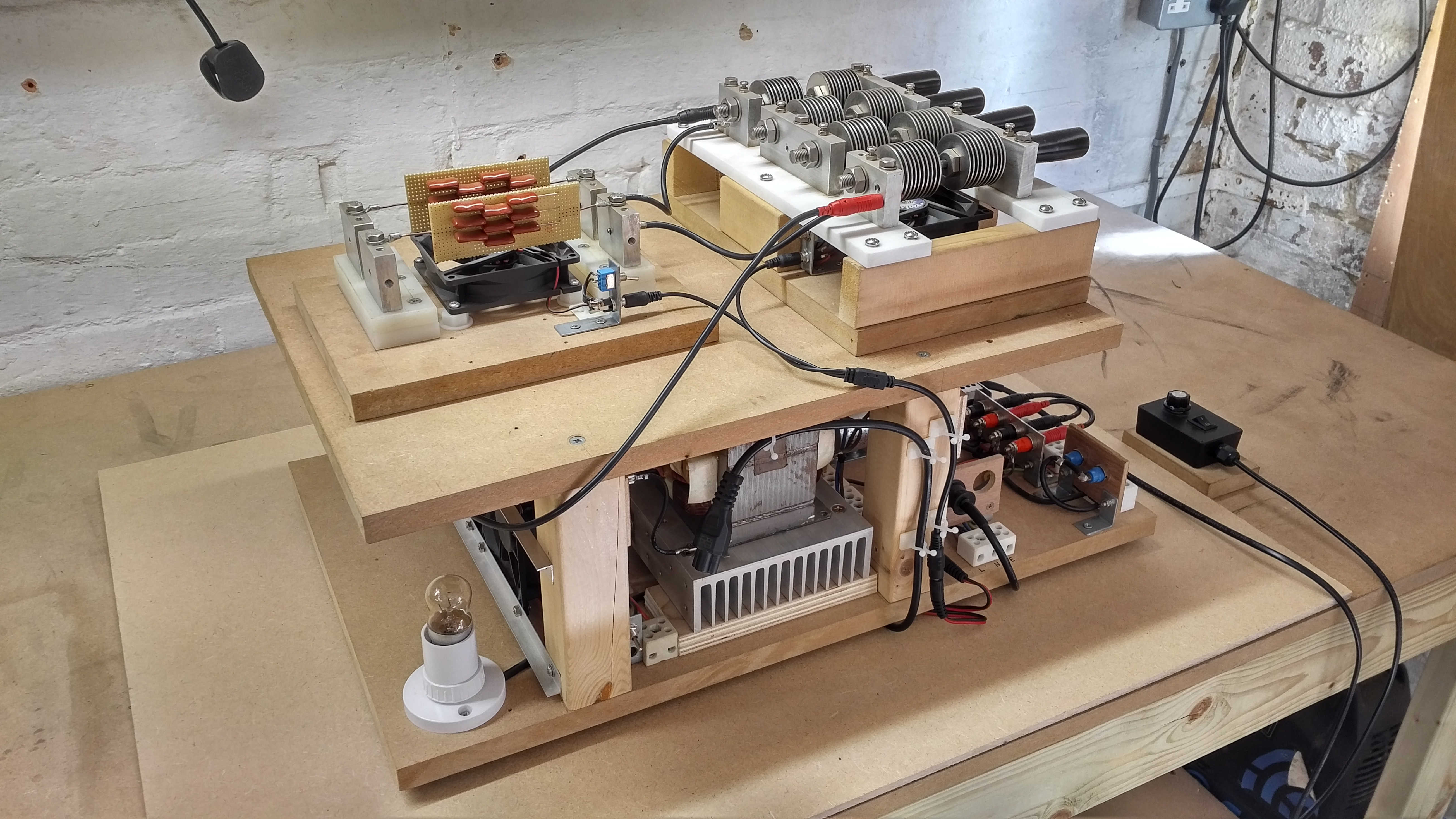
The complete spark gap generator (SGG), including the diathermy replica (DR), and the MMC capacitor bank unit, is shown in Figures 1 below, and mounted on top of, and connected to the high voltage supply:
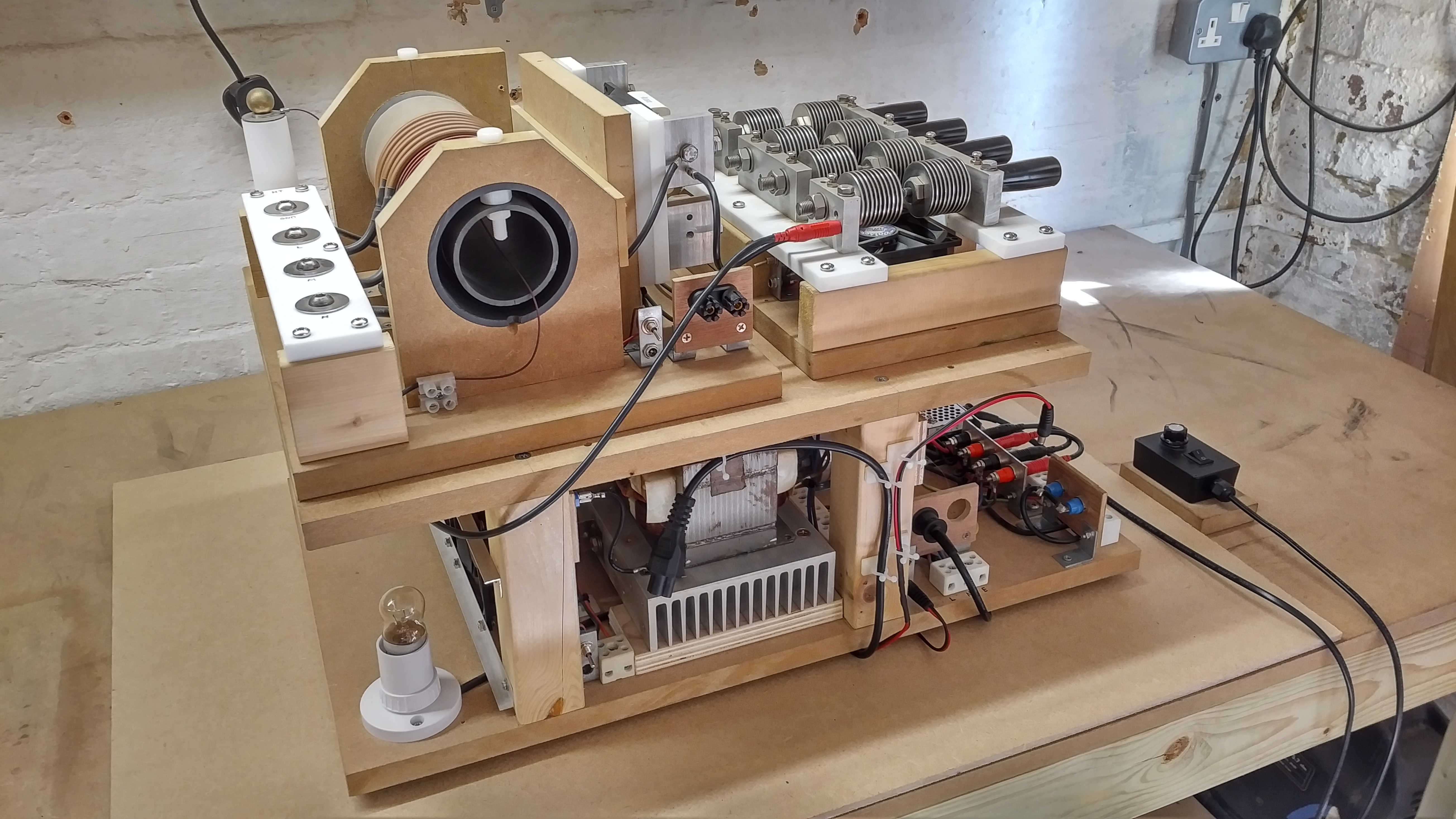


Far more consideration is normally given to the experimental components (e.g. coils), their construction, dimensions, materials, and the results that they yield, and much less on the generators that produce the high voltages and currents that are used to power the experimental apparatus.
Over time this appears to have led to an “air of mystery” surrounding the generators that are used in these types of experiments, quite besides a good generator is a complex and involved process to design and build, and can take much more time than any other system component to “get right”. Certainly when I started out by watching the experimental work of Dollard et al.[1,2], I was very much left with the impression that many of the unusual results obtained were mostly a product of the special generator and components used, and the experimental coils allowed these effects to be transformed, observed, and experimented with.
I have not been alone in these impressions, as I have received very similar comments from others in the field that have not actually built a working experimental system for themselves, but rather still feel that “air of mystery” that surrounds the generator and specialised components and materials in the systems construction. Only by building or contributing to a working experimental system, (including the generator), is it possible to really dispel this “air of mystery”, as it becomes possible to understand and characterise how the generator is producing the types of voltages and currents specific to its type.
In addition to this, many of the components referred to in important works such as Dollard et al.[1,2,3], may well have been more readily available in the 80s and early 90s, but are now quite scarce, and often command high prices for working items, or “new old stock” components. For example a 1920s H.G.Fischer diathermy machine used as the primary generator in the experiments of [1] are very rare, and when they very occasionally are available, they are expensive. Without understanding what is inside a generator such as this, and how it is working, it is very difficult to know how to build a comparable generator, or whether one will be able to gain the same types of unusual electrical phenomena demonstrated in works such as [1,3].
This was certainly the place I found myself in the early days where I wanted to begin by reproducing and confirming for myself the unusual measurements and results obtained by others, before using this as an established foundation to advance further in exploring my own ideas and insights regarding electricity, and the displacement and transference of electric power. When I started out there were no good examples of a working diathermy machine currently available, (especially in the UK), so I decided to design and build a diathermy replica for myself, and using readily available materials and components. If this generator could be used to explore unusual electrical phenomena then it would certainly for me increase my understanding enormously of how such generators are designed and constructed, whilst also dispelling the “air of mystery”, and providing a generator design that could also easily be used by others in the field. Later I did finally acquire an original 1920s H.G.Fischer diathermy machine and have been able to make a characterisation and comparison between the replica and the original.
The posts reporting the Spark Gap Generator – Parts 1 and 2 are the result of building a working high power diathermy replica, which is now routinely used in my daily experiments, and has contributed significantly in bringing me to a core understanding, that all parts of the electrical system play a specific role in the generation of unusual electrical phenomena. In the exploration into the displacement and transference of electric power each part of the system apparatus must first be measured and characterised carefully to establish a well tuned and balanced overall system, and where the electric and magnetic fields of induction are balanced and in a state of dynamic equilibrium.
From this point it is possible to experiment directly into the properties of electricity, and come to an understanding that the unusual phenomena observed are a product of the inner workings of electricity itself, where the generator and experimental apparatus are necessary to set up the conditions and boundaries required to explore these inner properties. The properties of electricity are there to be revealed rather than “generated”, which also assists greatly in dispelling the “air of mystery” that the generator is the source of the unusual phenomena, but rather, the instrument that provides the necessary tension to trigger the imbalance of the electric and magnetic fields of induction, and hence to observe electrical phenomena within the system. The differences here are subtle but hugely important to the overall understanding of electricity and particularly displacement of electric power.
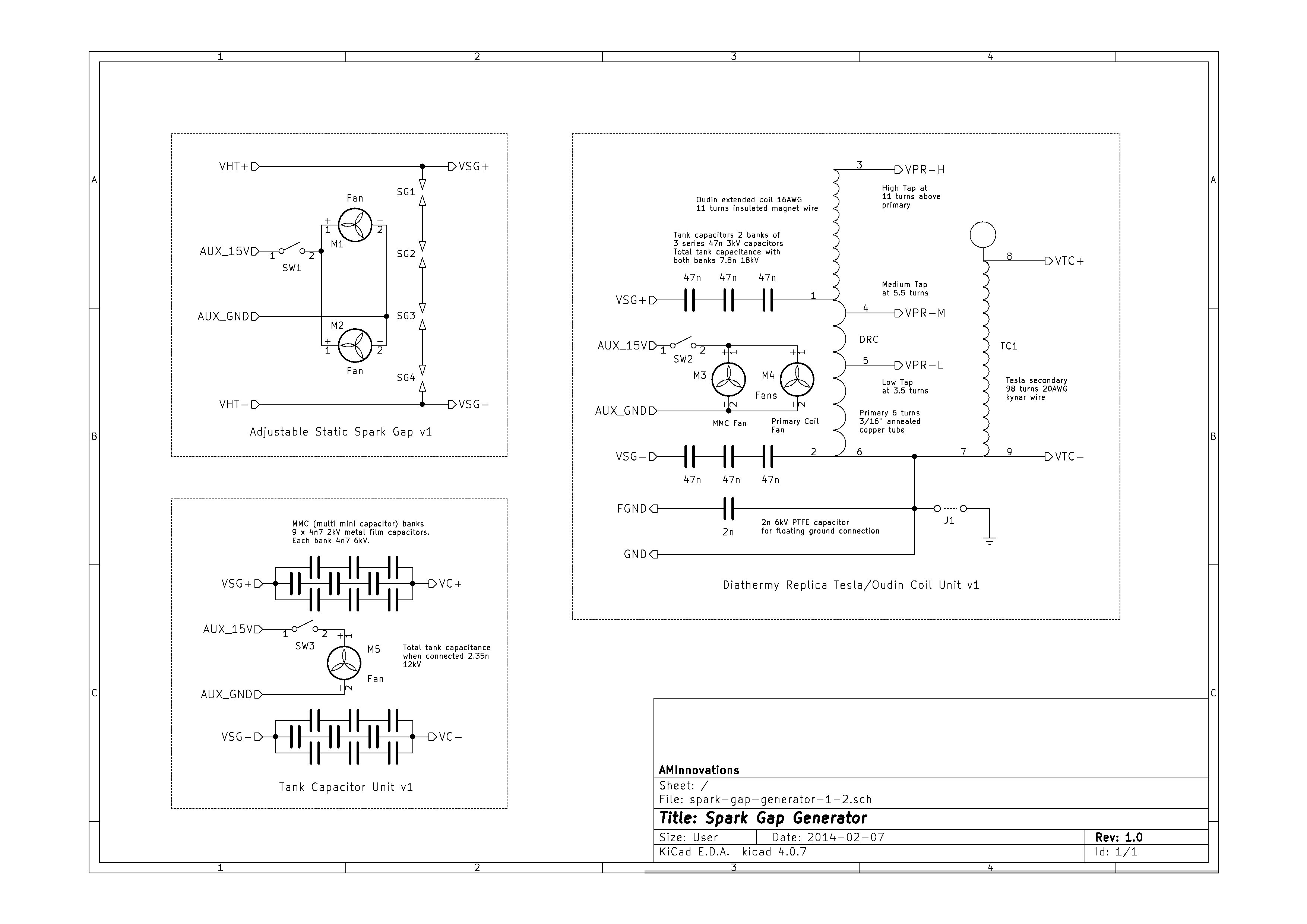
The circuit diagram for the SGG and peripherals is shown in Figure 2 below, or click here to view the high-resolution version.

In the early days in order to replicate the experiments and results of Dollard et al.[1] , it was considered that the diathermy replica (DR) should be as close as possible to the original, which of course posed a challenge when there was no original from which to take measurements, dimensions, construction methods etc. To overcome this a range of references from the internet were studied, along with available circuit diagrams. The most useful references proved to be a combination of material from [3,4,5], and allowed key dimensions and some circuit component values to be extracted from the images and videos.
Click on the following links to view circuit diagrams for various original H.G. Fischer (HGF) diathermy machines, the Model G2, the Model H, the Model CDC, and the Model A[4].
In any Tesla or resonant coil design it is first necessary to define the desired properties of the secondary coil. With this defined the primary and other components of the system can be designed around the secondary properties. In the case of the DR, and in the absence of any good measurement data, e.g. the resonant frequency of the HGF secondary, the DR secondary was designed according to the known and available dimensions of the HGF secondary, the wire size and type, and the number of turns, (mostly gained from [5]). The dimensions and wire were then adjusted for readily available materials and then key parameters extracted using the software Tccad 2.0[6]. The DR secondary coil properties were adjusted primarily to match F0 the primary resonant frequency of the secondary coil, while keeping the physical dimensions as close as possible, whilst using readily available material types and sizes. The original HGF and the designed and adjusted DR properties are shown in the following table:
| Original H.G. Fischer Model G Diathermy:
From reference pictures and video[5]: Turns: 90 Wire: Solid copper 20 AWG cotton-clad, total diameter 1.0mm Secondary Former (OD): 25/8“, 65.7mm
Secondary Coil length: 92mm Primary Former (OD): 31/2“, 89.6mm Primary Coil: 6 turns 3/16” copper tube Oudin extended coil: 11 turns 12 AWG solid (2mm) magnet wire From Tccad 2.0: L = 340uH C = 2.87pF F0 = 5066 kc/s Fλ/4 = 3978 kc/s Additional top load Cλ/4 = 1.78pF Wire length (WL) = 18.9m |
Diathermy Replica:
Adjusted for available materials to match F0: Turns: 98 Wire: 19/32 20 AWG Kynar (PTFE coated), total diameter 1.2mm Secondary Former (OD): 63mm (standard UK polypropylene pipe) Secondary Former OD + PTFETAPE + PTFEWIRE = 63.40mm Secondary Coil length: 120mm (the PTFE wire coating adds additional length) Primary Former (OD): 90mm (standard UK polypropylene pipe) Primary Coil: 6 turns 3/16″ annealed copper tube Oudin extended coil: 11 turns 14 AWG solid (1.6mm) magnet wire From Tccad 2.0: L = 350uH C = 2.84pF F0 = 5065 kc/s Fλ/4 = 3806 kc/s Additional top load Cλ/4 = 2.03pF Wire length (WL) = 19.4m |
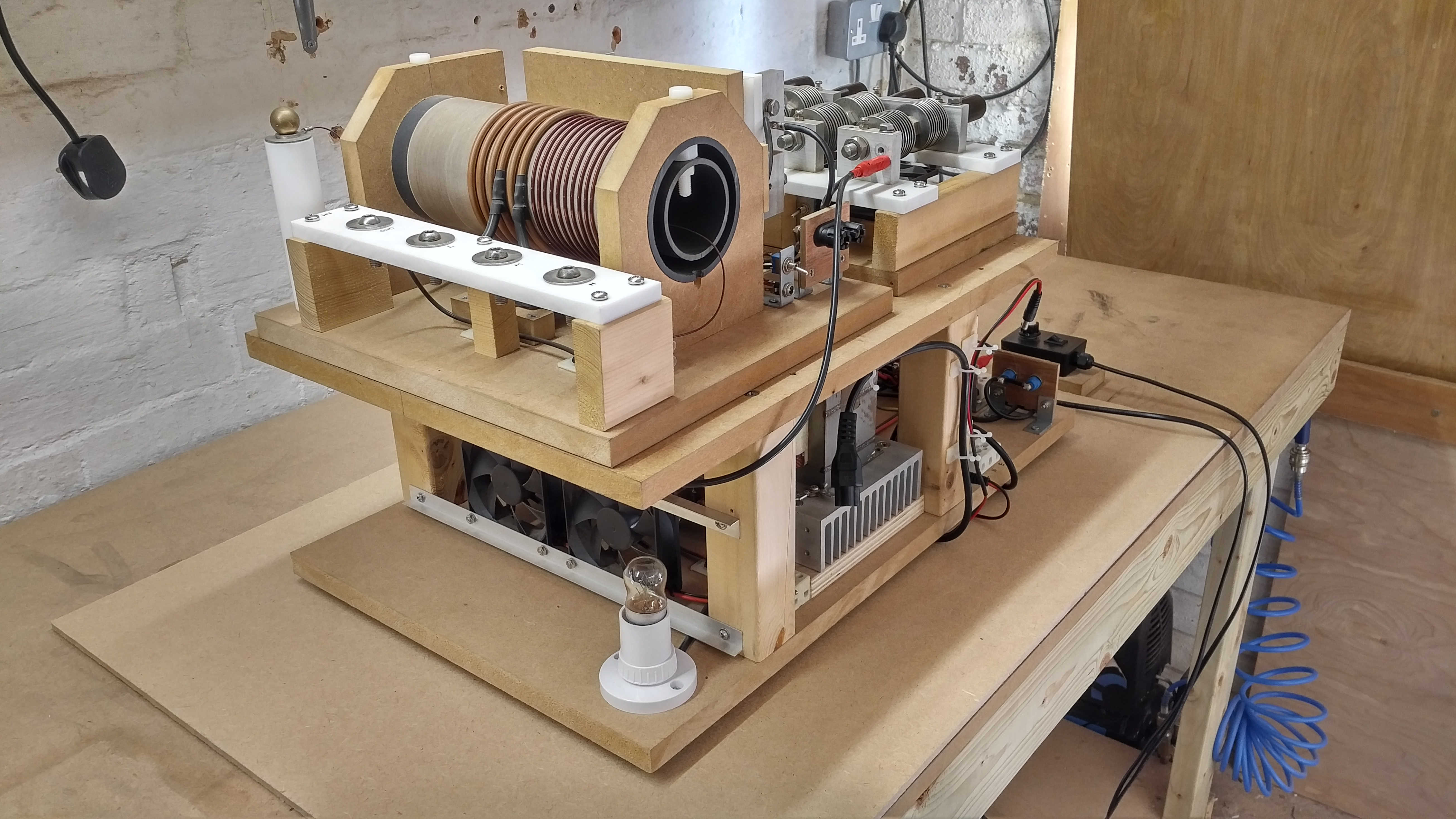
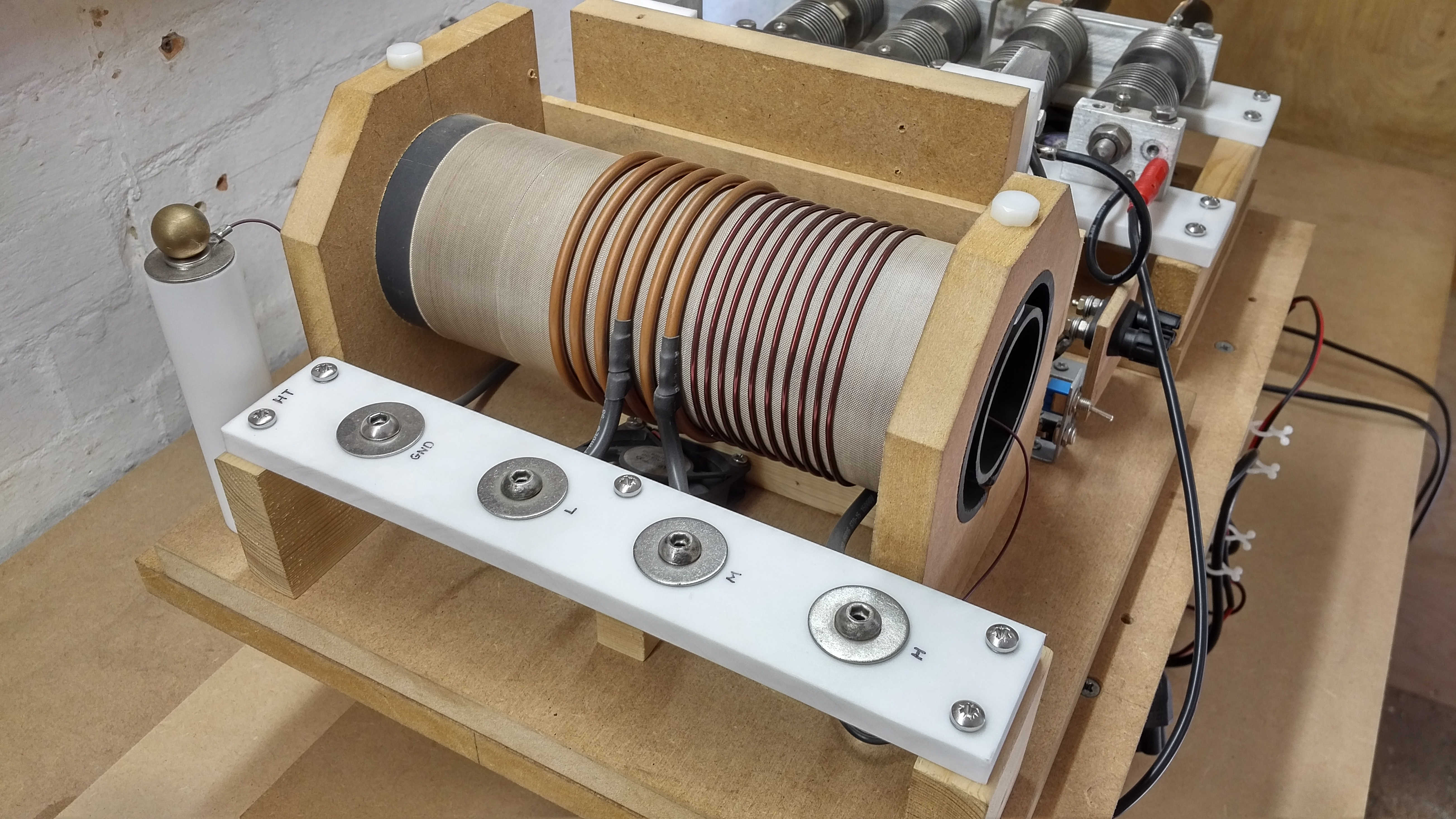
Figures 3 below show how the Tesla/Oudin unit was constructed, and the types of materials used in a simple open structure that can be easily adjusted and modified according to the experimental requirements. Components are mounted on a mdf wooden base, and conductors insulated from the mdf using PTFE and Nylon 66 mounts, bolts, and nuts.
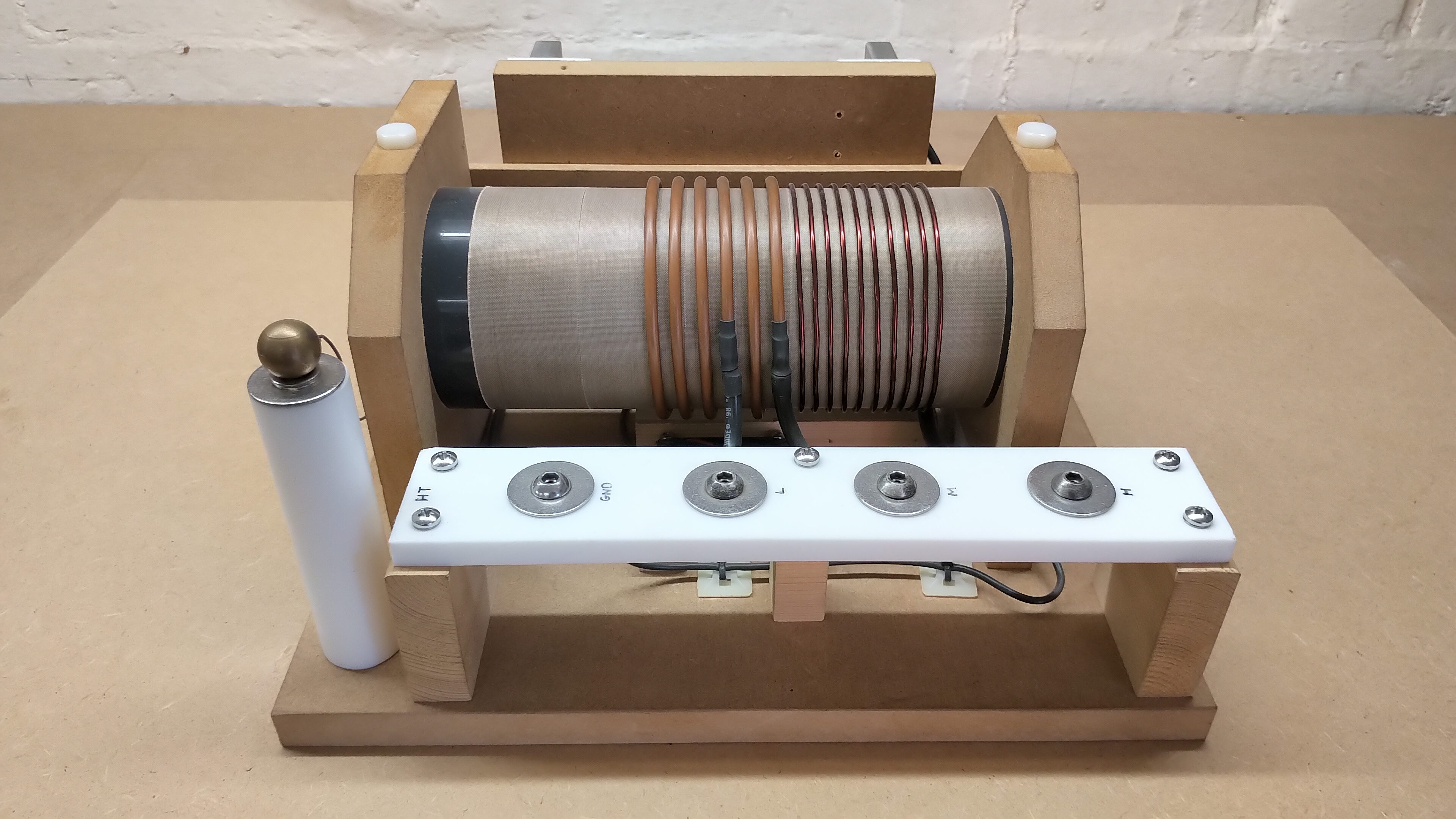
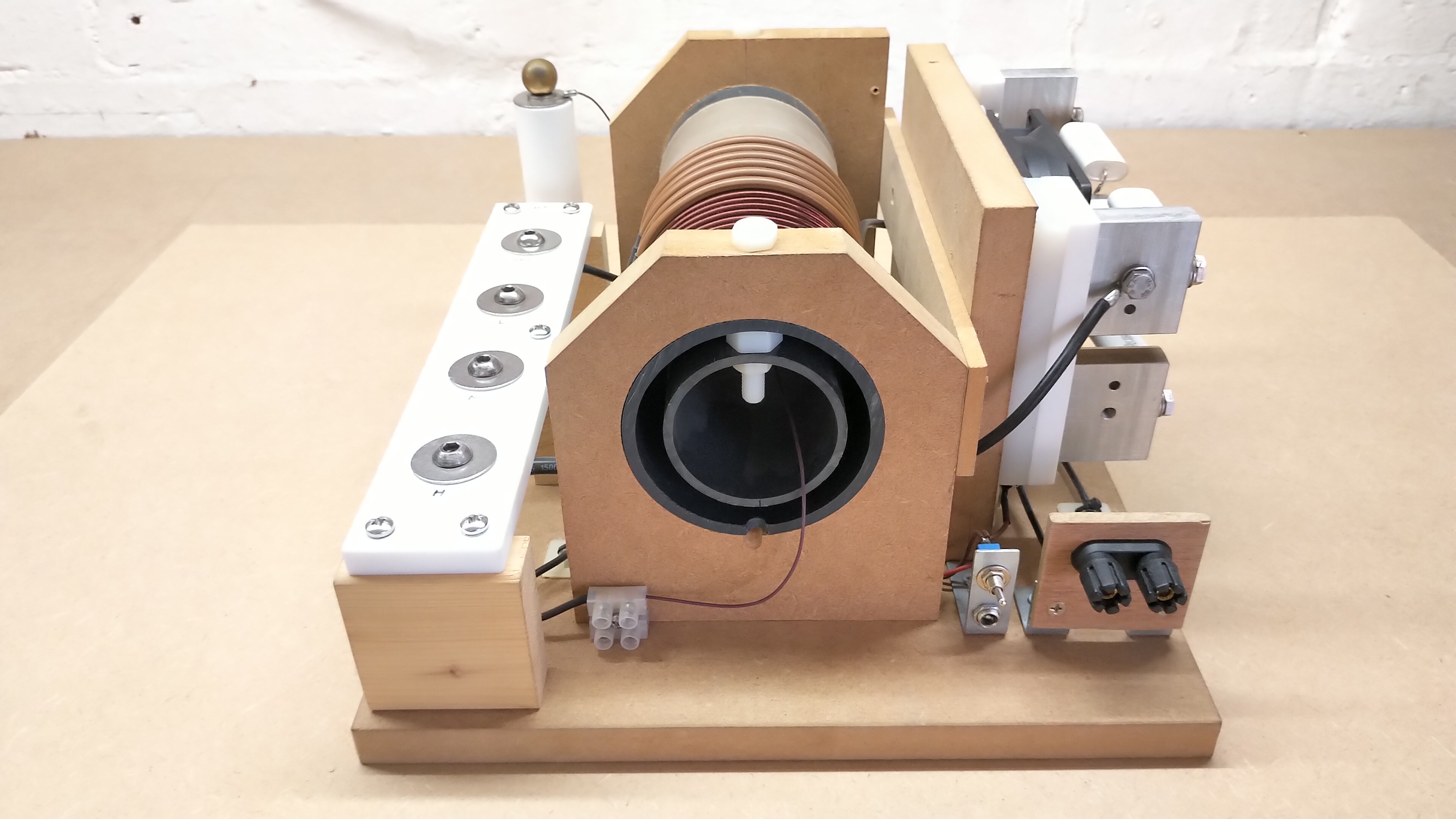
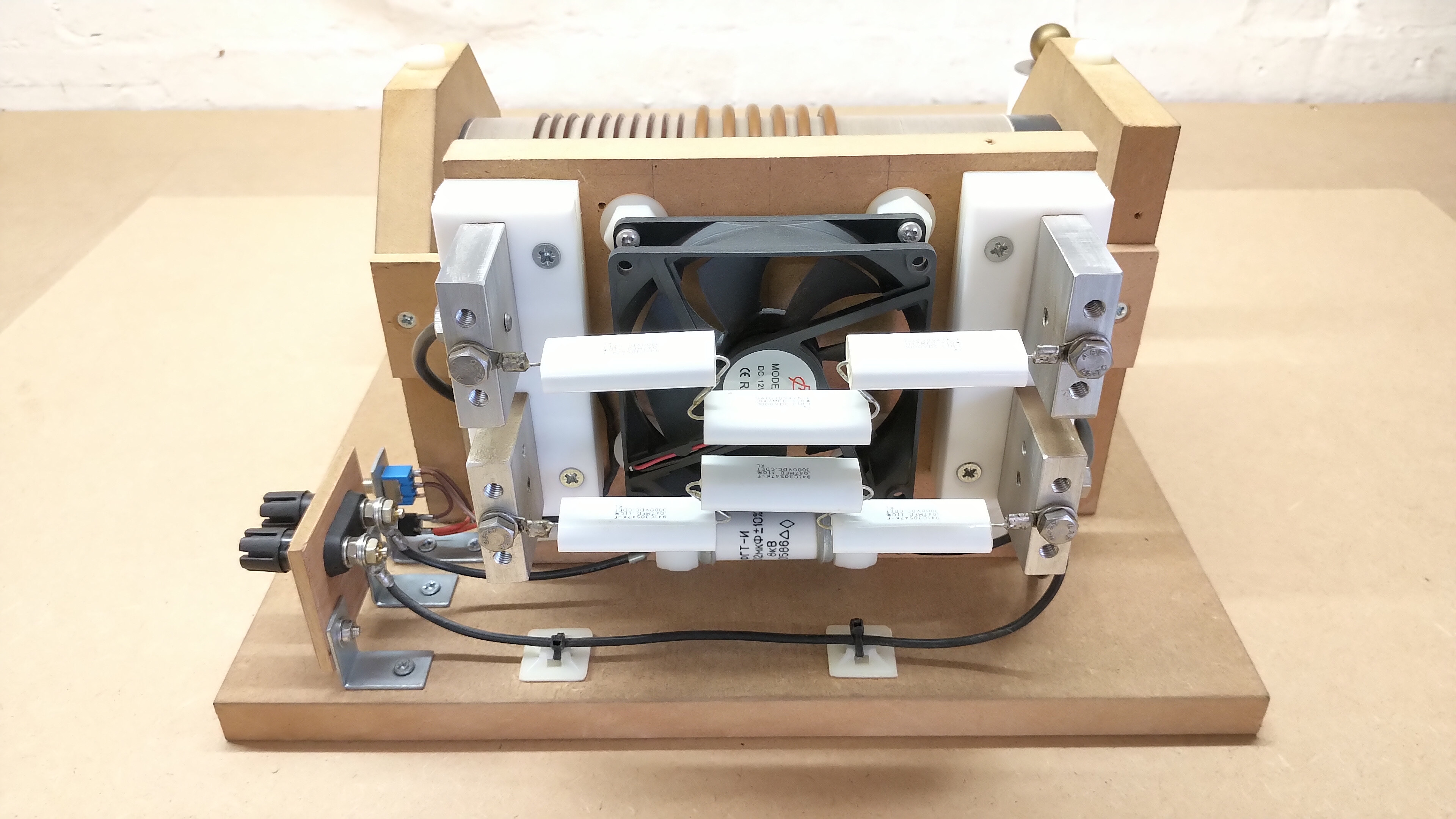
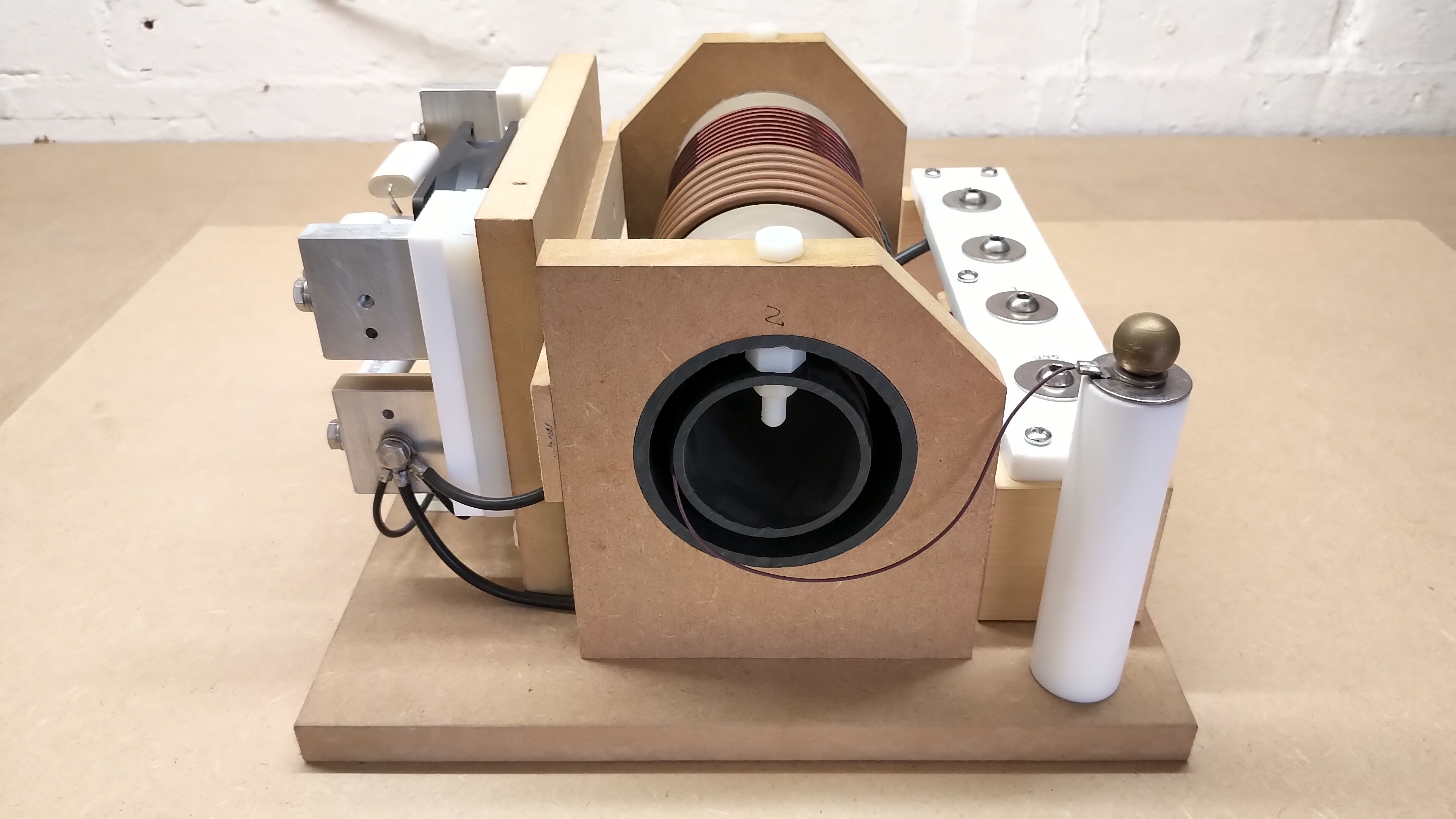


The formers of the primary and secondary coils were first coated with PTFE tape to improve the thermal barrier between the coil and the polypropylene former material when running at high output powers. In addition a small low voltage fan was located under the primary coil to help keep the primary cool at sustained high power outputs. The Tesla EHT output and the HT output taps are all mounted on PTFE insulators both for electrical isolation, but also for good resistance to melting and burning which can occur when drawing discharges from these terminals. Nylon 66 can also be used here, but has lower thermal resistance to discharges, but has the benefit of being a much cheaper material than PTFE.
It is important to note that the secondary coil is located in the primary at the opposite end to the Oudin extended coil. In an early version of the DR the secondary was incorrectly located at the same end as the Oudin extension, which because of the increased tension in both coils easily causes breakdown between the two coils, and led to burn-out of the first secondary coil. The tank capacitor banks are made from 3 series connected Cornell Dubiler 941C03 series 3kV polypropylene film capacitors each of value 47nF, which combined gives 15.7n 9kV for each bank. These tank capacitors have been proven to be long-lasting, and robust, and have never been changed, even with input powers in excess of 1.5kW and even up to 2.2kW for short bursts of power.
The tank capacitors are force air-cooled, and mounted on insulated conductors which allow for easy connection and adaption to the circuit under test. The capacitance of the tank was initially higher at around 47n to match more closely the HGF schematic of the Model A, but was reduced to its current value after the real HGF was acquired and measured. At 47n the available output power was quite a bit less than with 15.7n per tank, as the primary resonance is pushed lower and further away from that of the secondary, hence reducing the primary currents, and hence the power coupled from the primary to the secondary.
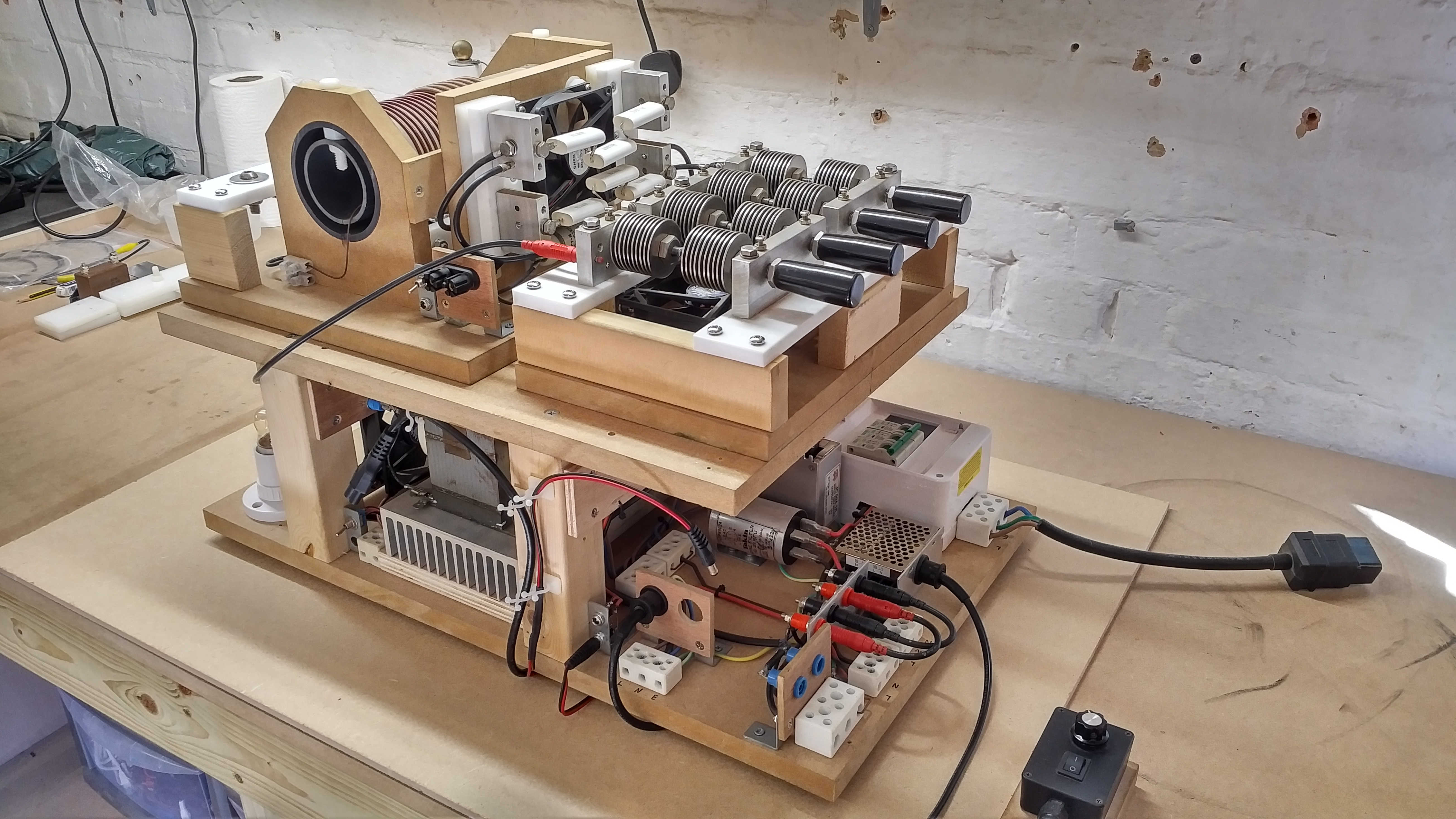
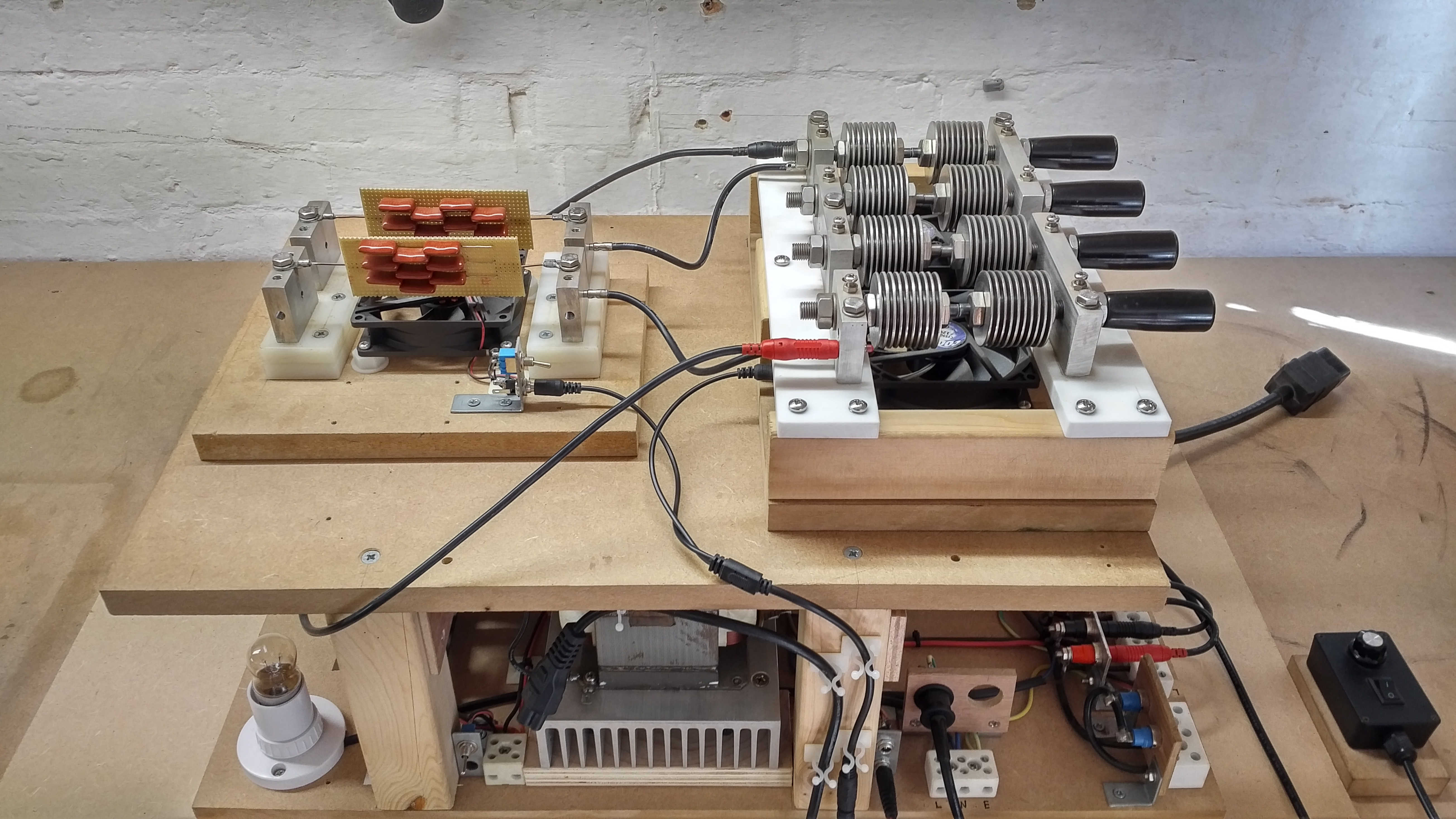
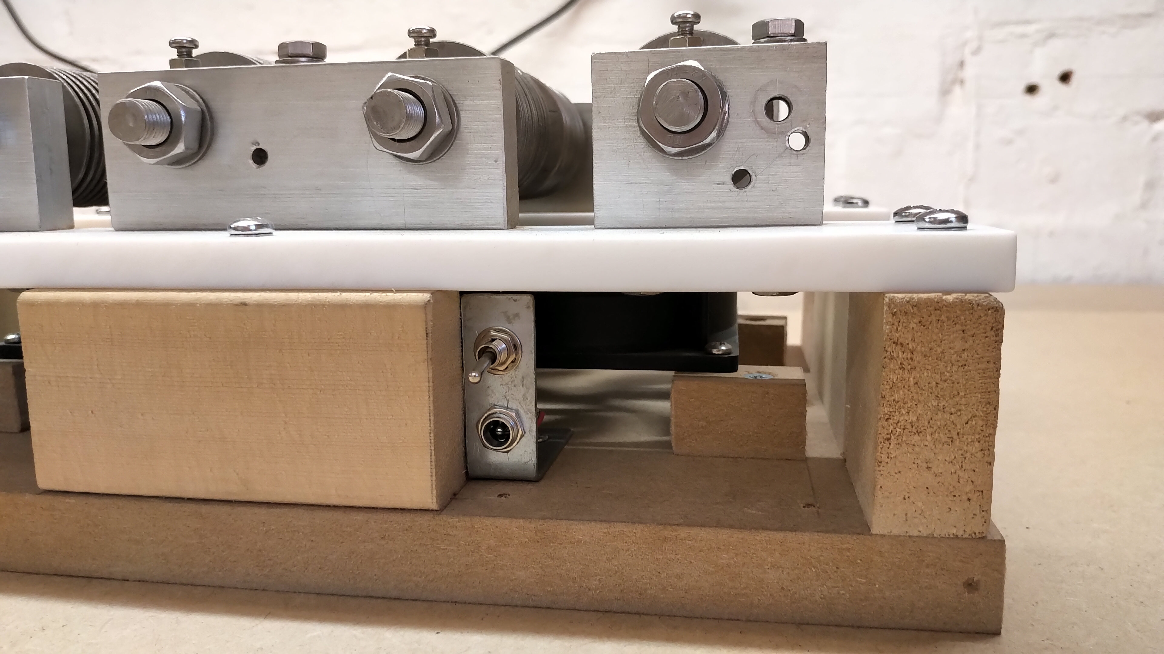
Figures 4 below show how the static spark gap (SSG) unit was constructed.
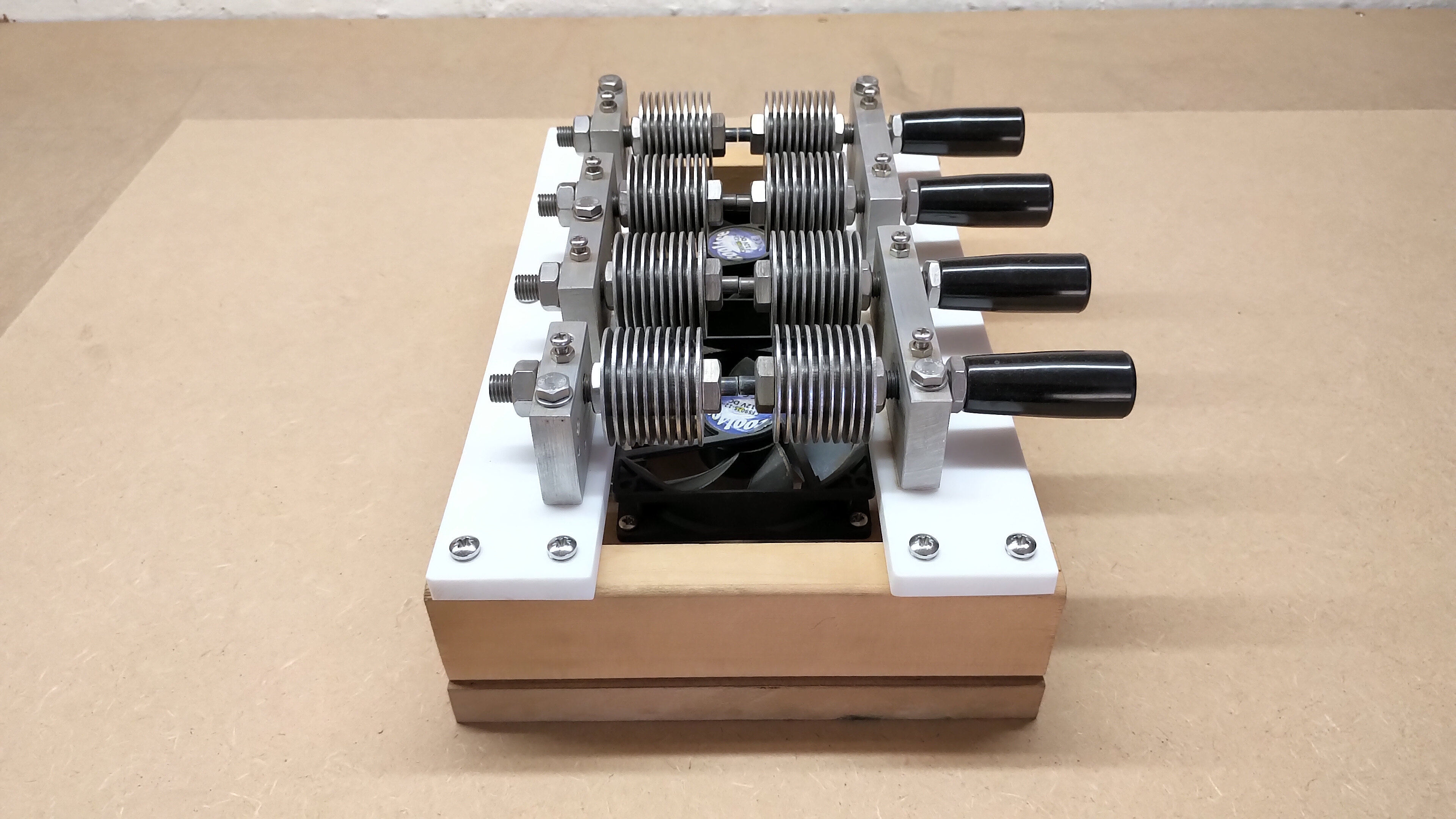
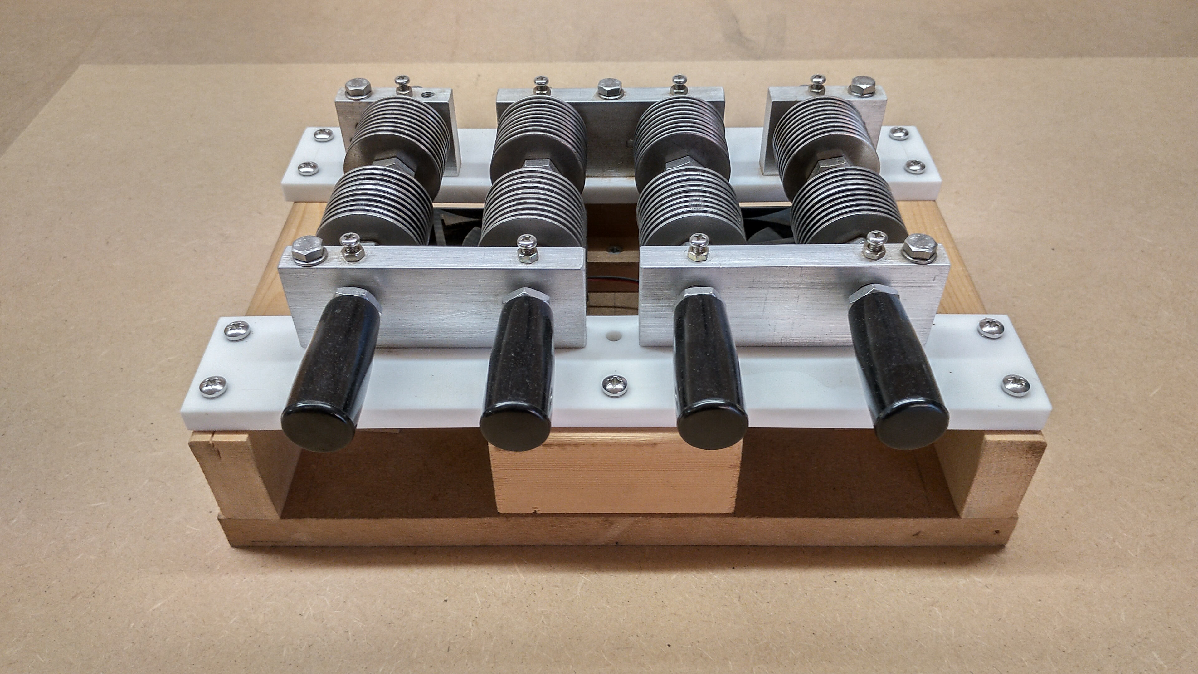
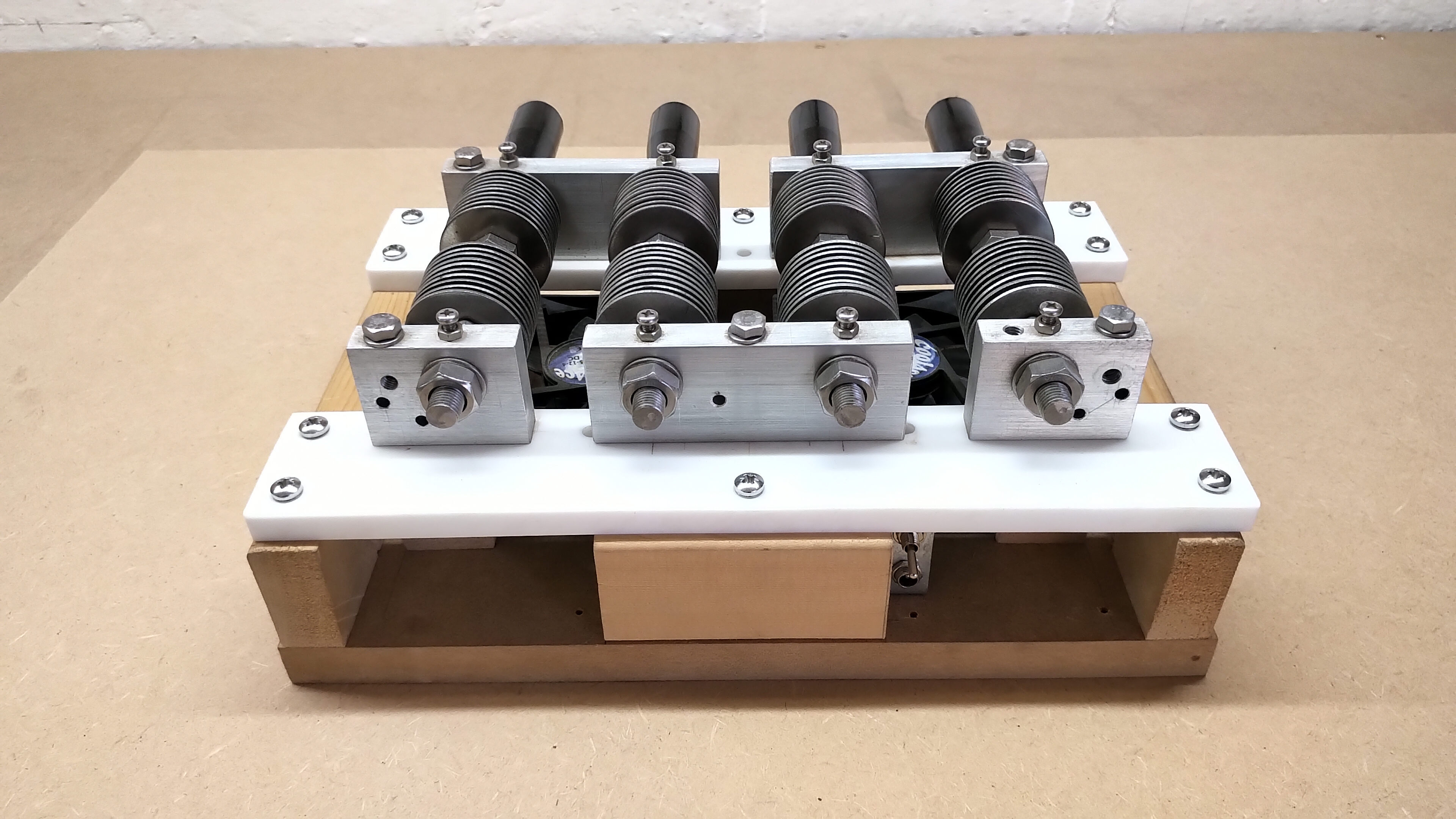
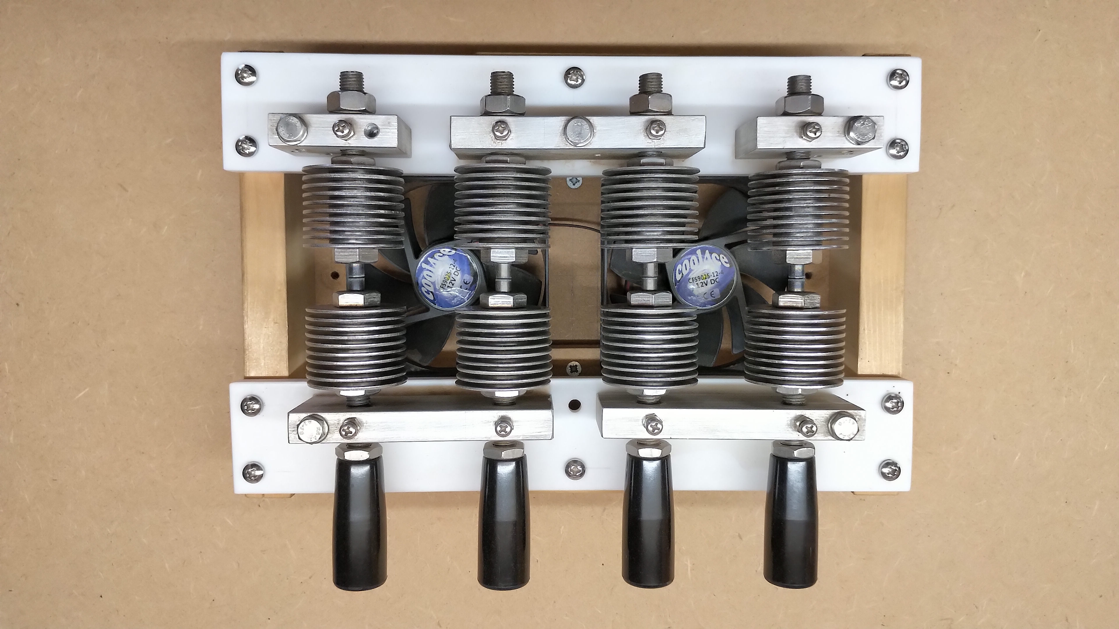
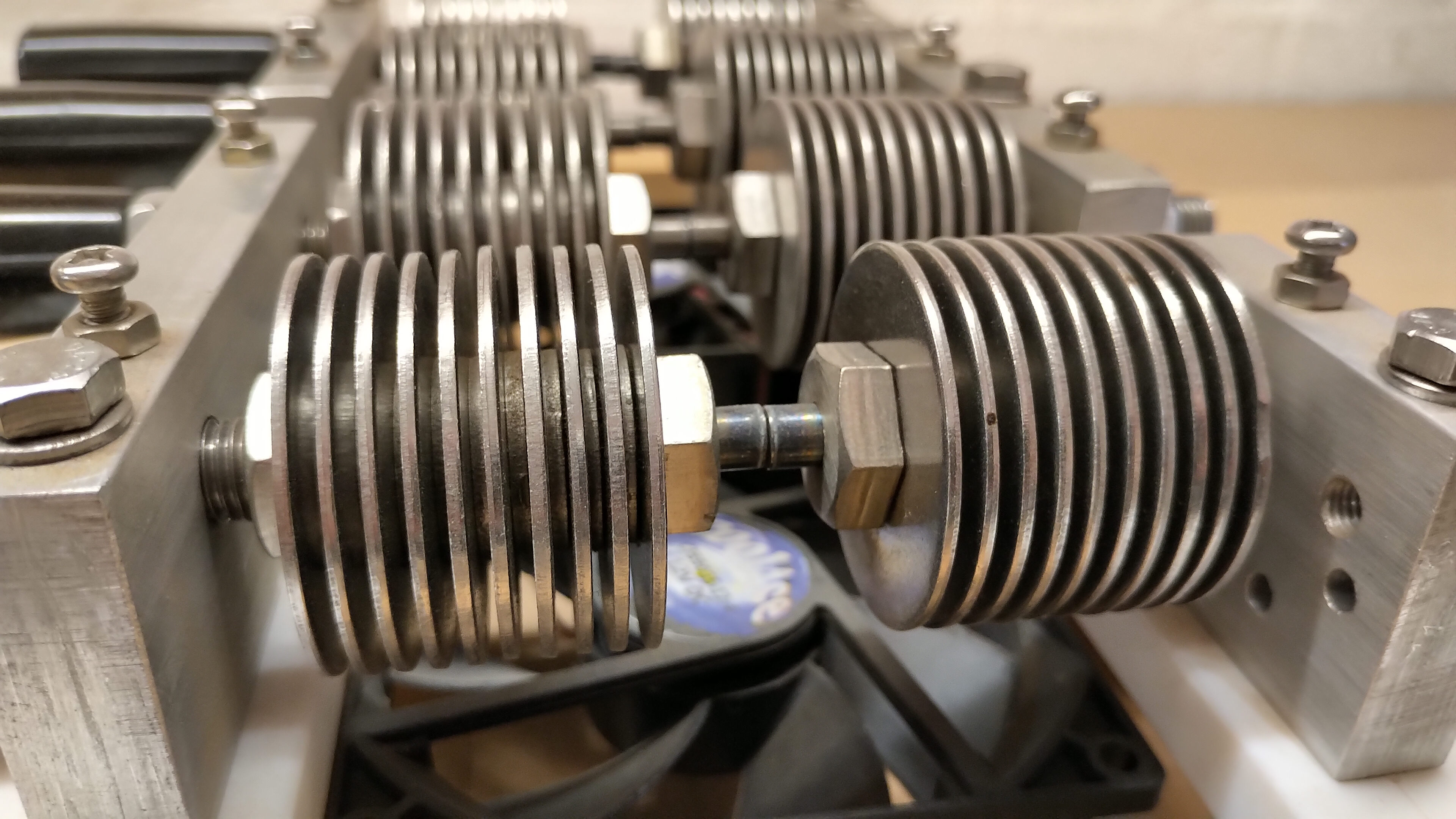


The SSG unit was at the time the most difficult unit to build when only a large pillar drill, large vice, and bench sander were available in the workshop for mechanical construction. Each electrode of the spark gap is made from 1/4” diameter 99.9% pure tungsten rod 1″ long, (not to be confused with tungsten carbide rods), which were pressed using the vice, into the centre of a drilled A2 stainless steel fine pitch bolt. The bolt had a 6.2mm hole centre drilled, by mounting the bolt in the drill chuck and clamping the drill stationary on the stage, and opposite to how a drill press is normally used. This arrangement made a very rudimentary “lathe” and made it easier to drill a centralised 1.5″ hole down the centre of the bolt. The tungsten electrode was then pressed into the bolt leaving 5mm externally for the spark electrode. Alternating stainless steel washers (large and small) were then threaded onto the bolt and finally tightened with a thin stainless steel nut to form the cooling fins of the electrode body.
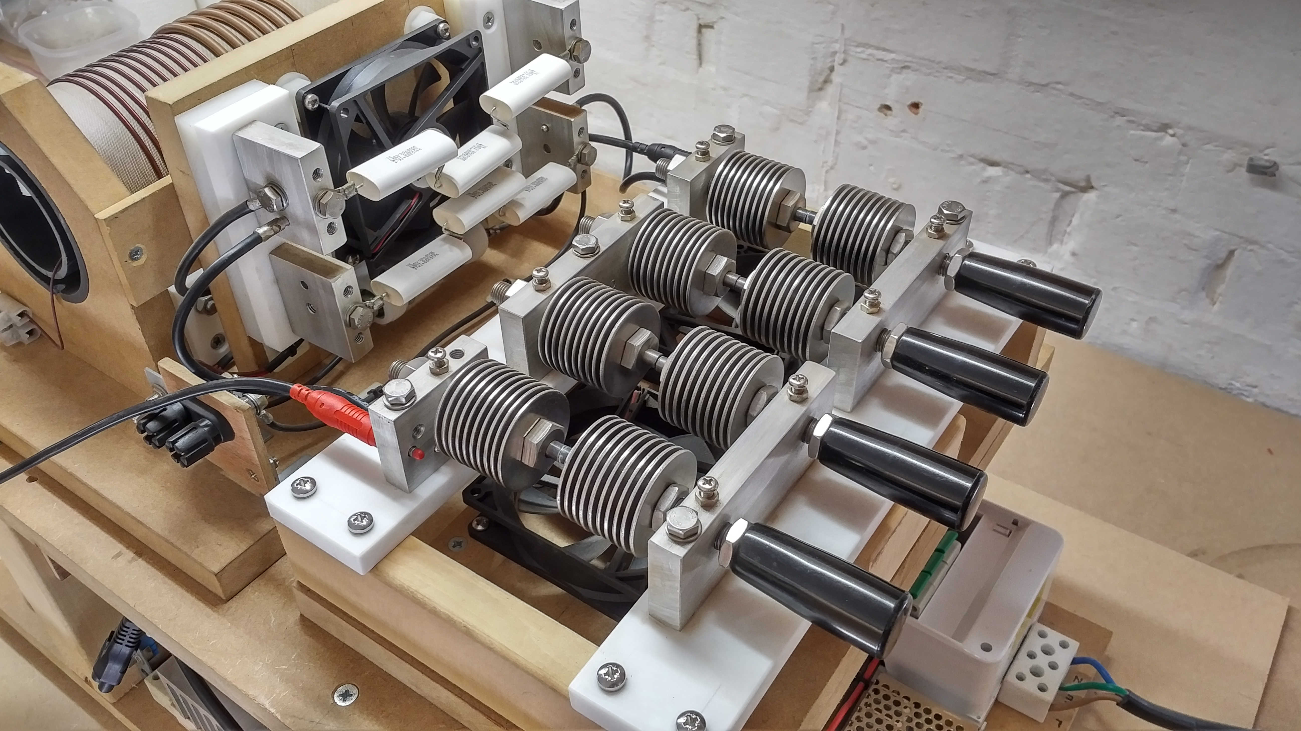
Each pair of electrodes were then mounted in threaded aluminium blocks, locked in place with a nut on one side, and with a threaded bakelite handle on the other, to allow adjustment of the spark gap space by winding the bolt in or out of the aluminium block. The aluminium blocks were arranged and mounted to form a series connection of all four spark gaps, and also allowing for tapping from any of the 4 stages for experiments using a single gap, all the way up to 4 series gaps, or 4 parallel gaps with shorting shunts. The adjustable electrode was tensioned in the alumium thread by a small compressed nylon rod, ( from an M3 nylon bolt), which was inserted in a vertical hole drilled above the thread, and then tensioned using a screw locked in the correct place by a nut.
The aluminium spark gap blocks are mounted onto PTFE insulators and then mounted to a wooden base where each gap is suspended above force cooling provided by a pair of low voltage plastic fans mounted into the base of the unit. Overall the SSG unit is robustly constructed and can withstand very large powers in constant use. Tuning of the gaps for optimal running can be made carefully during operation via the four insulated adjustment handles, and is demonstrated in the operation video in Part 2.
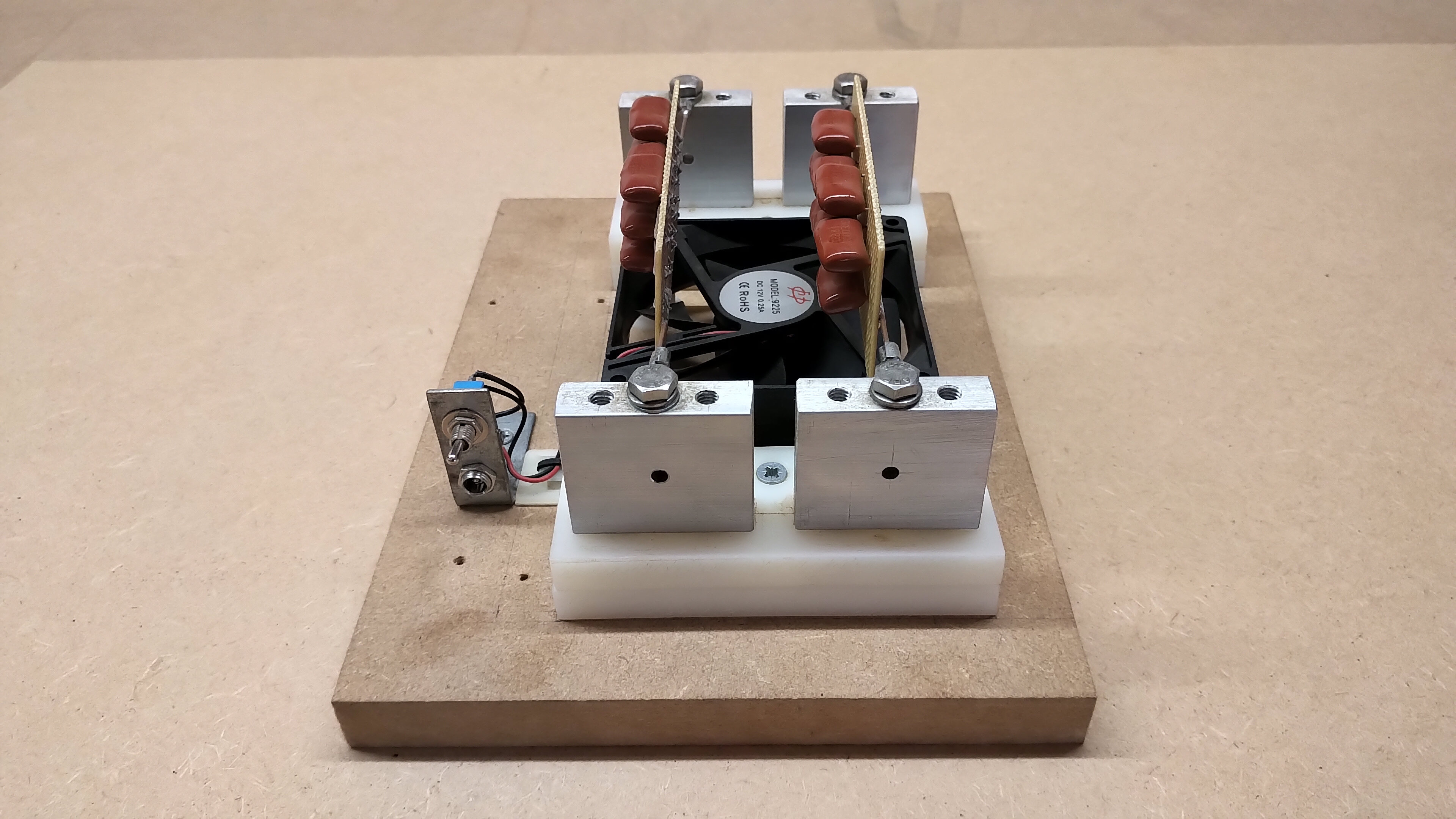
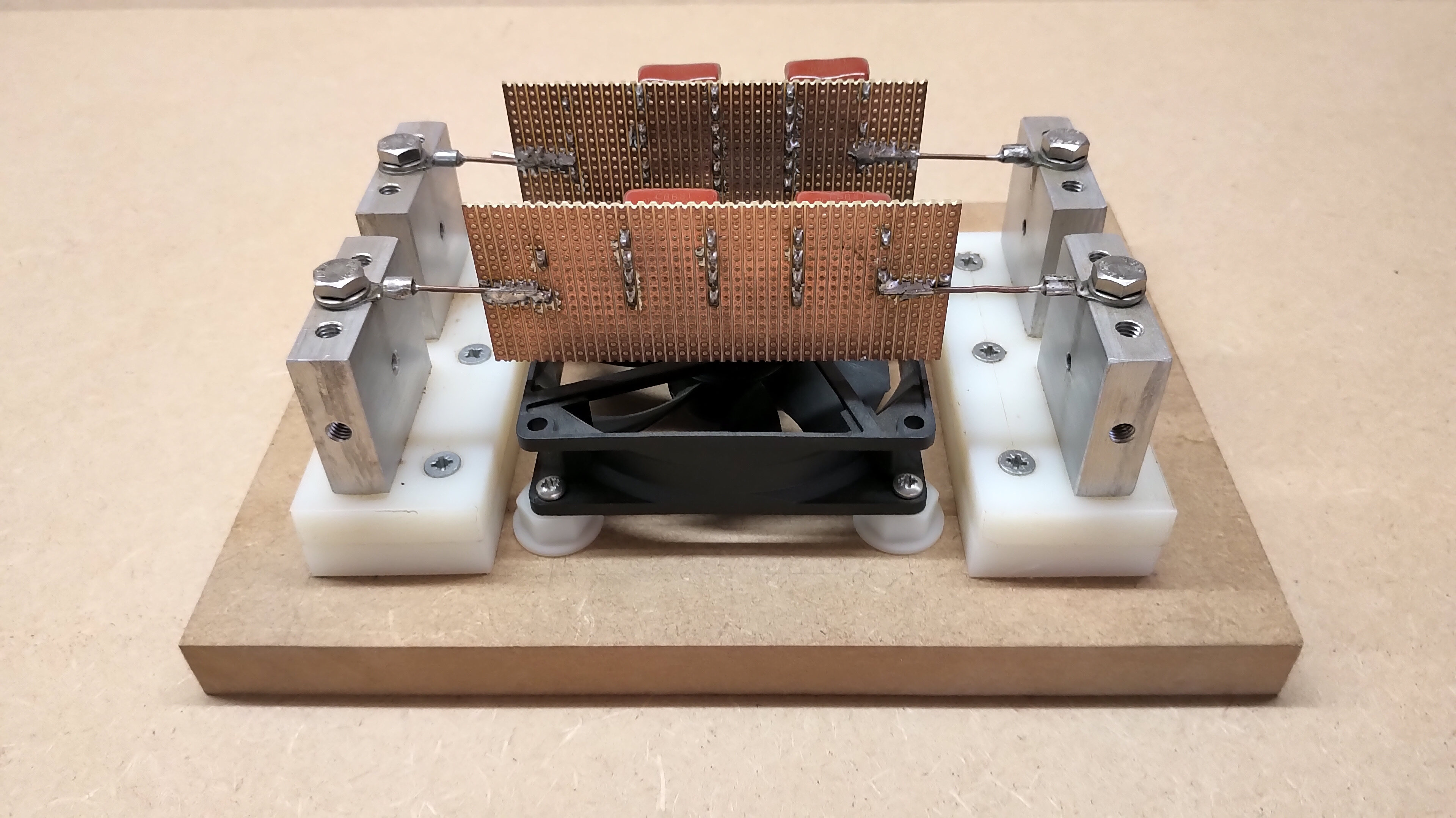
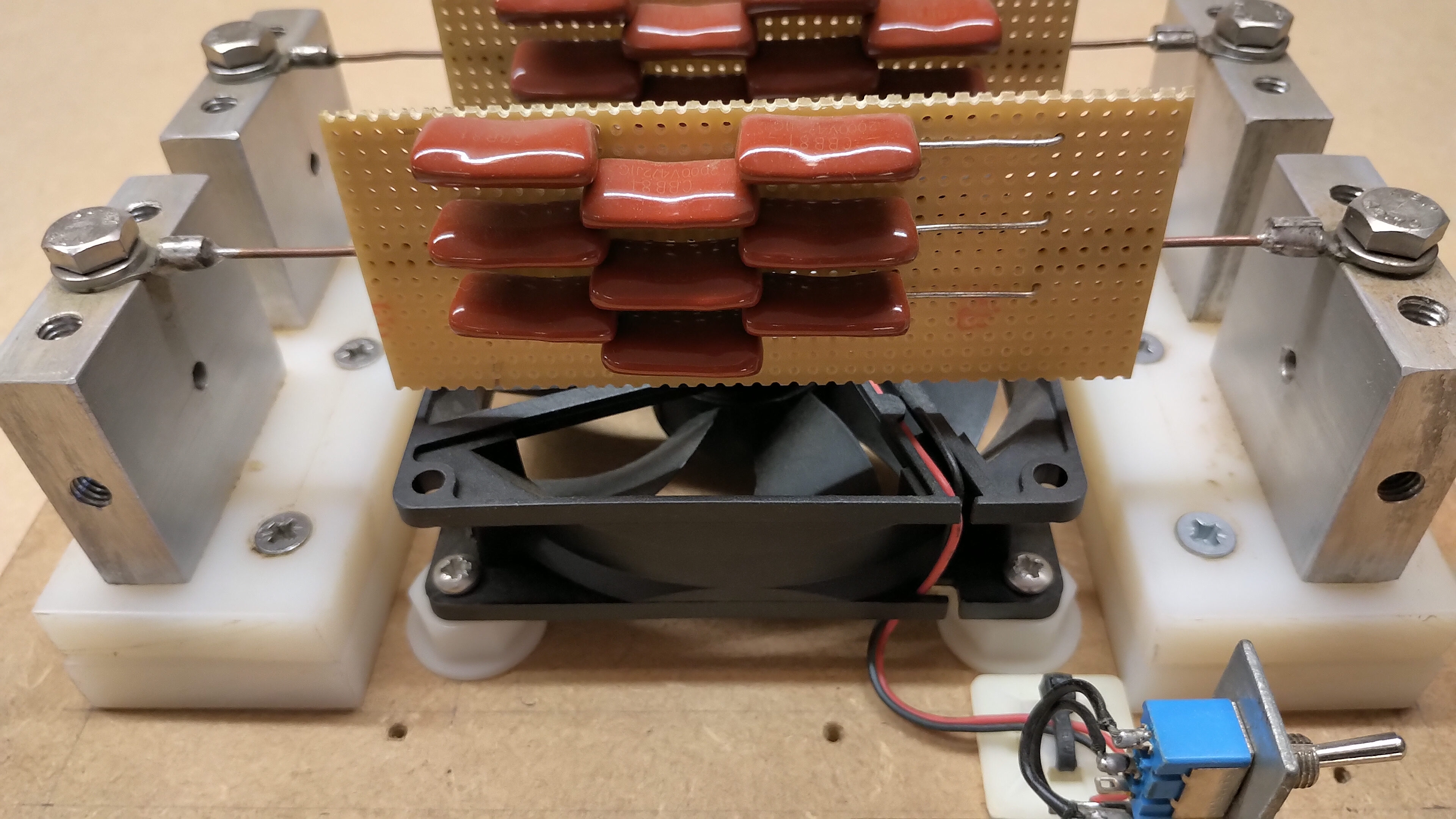
Figures 5 below show the MMC tank capacitor bank (TCB) which was used to remove one of the tuned primary stages, and hence increase the efficiency and optimisation of the generator driving, for example, the tuned primary of a TMT (Tesla magnifying transformer).
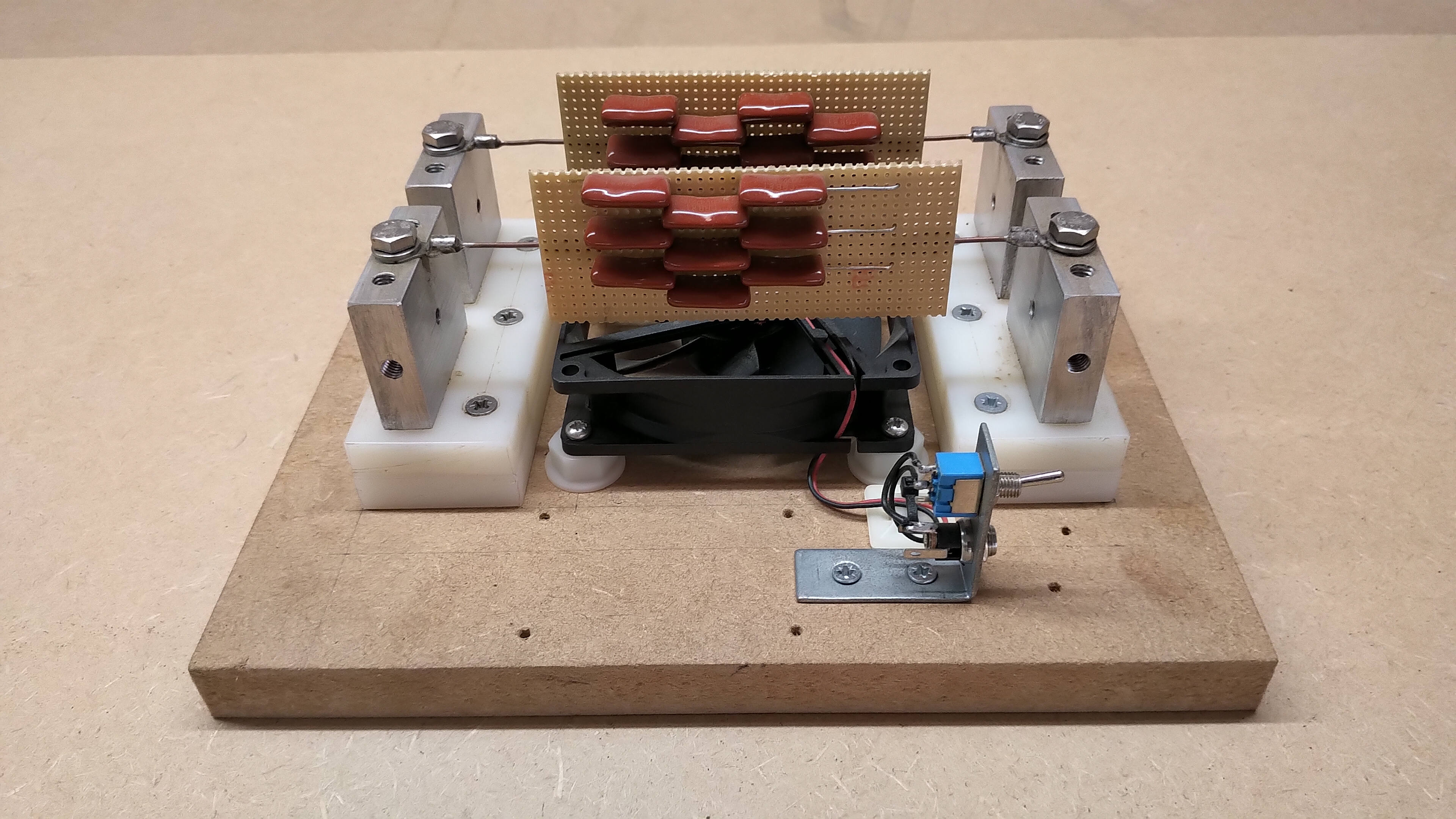
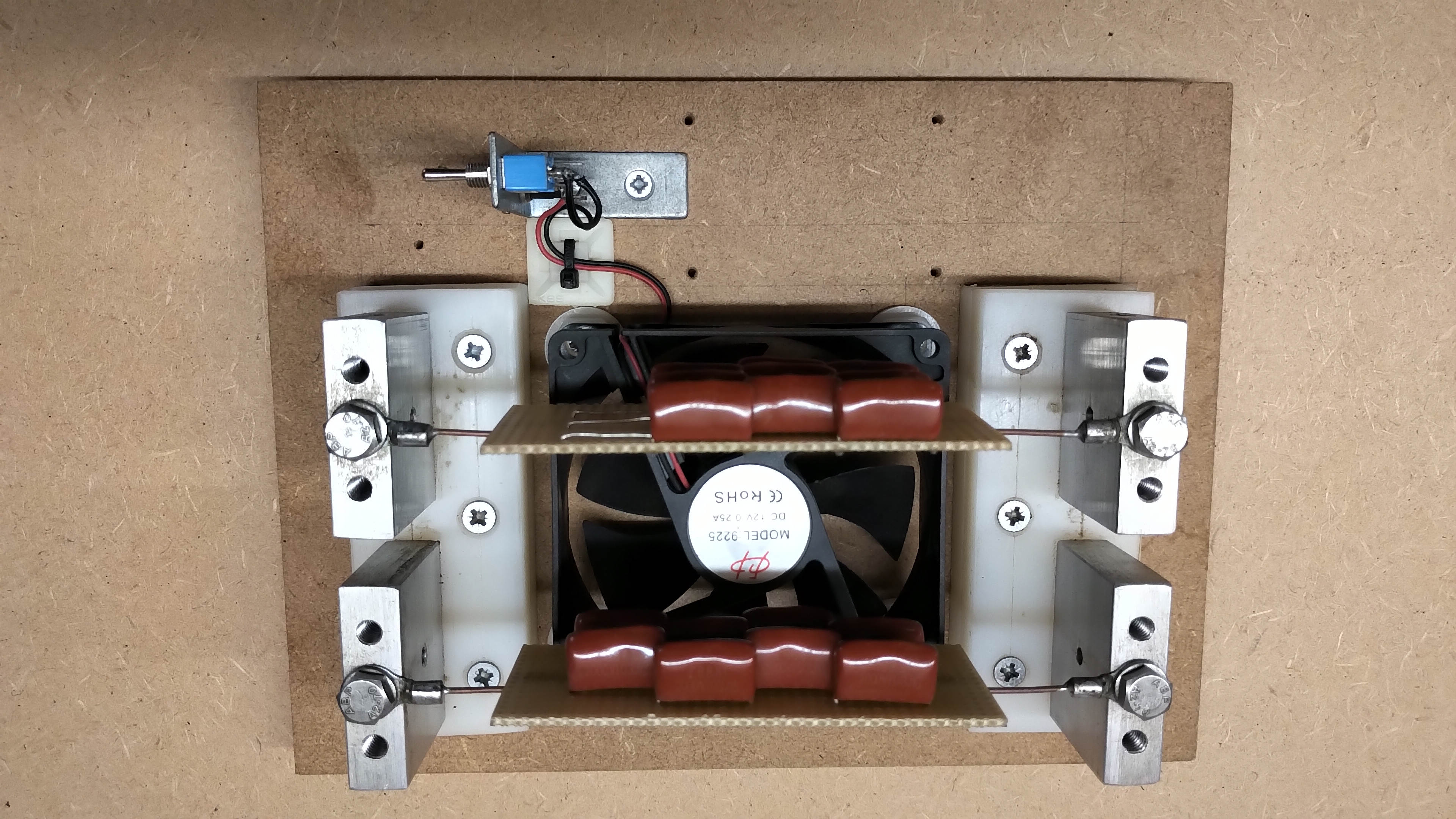


The SGG used with the DR as a generator is most commonly connected with one of the L, M, or H outputs to the primary stage of a tuned TMT, of which the primary stage would typically consist of a coil with a parallel tuning capacitor. In this arrangement the DR, which in itself is already a tuned primary stage, is now connected to another tuned primary stage. Whilst this was useful for preliminary experiments in confirming the key experiments and results of Dollard et al.[1,2] and keeping the generator as close as possible to an original HGF, it has been shown to be more efficient to eliminate the double tuned primary stage by removing the DR and placing the TCB in its place.
The TCB is simply a standalone capacitor unit exactly the same design as used in the input to the DR. Here the TCB is shown with two pcb MMC banks, but the Cornell Dubilier 941C03 series banks could equally as well be mounted in the same way. Figures 1.6 and 1.7 show how the TCB is connected directly to the SSG, and then in turn the output of the TCB is connected directly to the input of, for example, the tuned primary of a TMT, or some other experiment or load. This creates a resonant drive circuit with the TMT coil in series resonance with the TCB capacitors, and is exactly the same arrangement as internally for the DR, and the HGF. Use of the TCB in replacement for the DR has allowed for an easier and more accurate resonant match between the SSG unit and the TMT load, and with greater power transfer between the two units. Impedance measurements are also simplified by removing one resonant circuit from the generator chain. A very wide range of capacitors can be mounted on the TCB, and for higher power experiments up to 2.5kW output power, force cooling is available via the low voltage fan in the base of the unit.
Overall the spark gap generator whether used with the DR unit or the TCB unit at the output, has proven to be a robust and reliable generator for a wide range of experiments. It has enabled the replication of the key experiments as presented by Dollard et al.[1,2,3,4], as well as forming a flexible and powerful tuned static spark generator for my own experiments in the displacement and transference of electric power, as well as telluric transmission experiments.
Click here to continue to part 2 of the spark gap generator where the operating characteristics are measured both in frequency and time, as well as a short video to show its general operation and running.
1. Dollard, E. & Lindemann, P. & Brown, T., Tesla’s Longitudinal Electricity, Borderland Sciences Video, 1988.
2. Dollard, E. & Brown, T., Transverse and Longitudinal Electric Waves, Borderland Sciences Video, 1988.
3. Dollard, E. & Mackay, M., Tesla Radiant Energy Experiment, Bedini-Lindemann Conference, June 29-30, 2013.
4. Mackay, M. & Dollard, E., Tesla’s Radiant Matter Replication, 2013, Gestalt Reality
5. Sergey Z., Fischer Diathermy Narrating and Exploring a 1920’s Tesla Coil, May 2014, Youtube
6. Chapman R., Tccad 2.0 for Windows, 2000.