The Wheelwork of Nature – Vibration, Frequency, and Discharge Form

In this follow up experiment in the Wheelwork of Nature series we take a look at vibration, frequency, and discharge form that results from a set of Tesla coils designed to cover an operating frequency range between 300kc and 4Mc. If you have not done so already I recommend reading or reviewing the first experiment in this series The Wheelwork of Nature – Fractal “Fern” Discharges, which will set the basis for this current experiment. In the original experiment a range of experimental variations were tested in order to identify the origin of the fractal “Fern” discharge form, which is a distinct and significant departure from the discharge form normally observed in Tesla coils constructed using a basic standard design format, and constructed with readily available materials and processes. Variations to the experiment included, changing the matching and tuning of the Tesla coil, the excited resonant mode, the generator waveform, the type of vacuum tube used as a generator, and a top-load on the Tesla coil. The only significant variation to the discharge form was noted between the upper and lower parallel resonant modes of the Tesla coil, and hence it was concluded that frequency, or more correctly vibration, of the Tesla secondary coil was key to the nature and form of the fractal “fern” discharge.

The original coil was theoretically designed with a series resonant mode frequency of the secondary ƒSS ~ 3.5Mc in the 80m amateur radio band, and was subsequently measured using a vector network analyser to have a series fed fundamental resonant frequency ƒSS = 3.44Mc. When this was combined with a primary coil and RF ground it was found to reduce to ~ 3.18Mc. The upper and lower parallel resonant modes were found to be around 2.7Mc and 3.4Mc. The generator used was a basic class-C Armstrong oscillator using a single GU5B vacuum tube, and dual 883C vacuum tubes in the variation generator. This form of generator will oscillate readily at the upper or lower resonant parallel modes and can be tuned over a frequency band using a vacuum variable capacitor as a parallel tank capacitor in the primary circuit. This gave a tuned range from low end of the lower parallel mode at ~ 2.4Mc to the high end of the upper parallel mode at ~ 3.6Mc. Across this entire tuned range the discharge form was the fractal “fern”. The only significant variation was at the upper parallel mode, where the fractal “fern” appeared more compact, tightly formed, and with more dense secondary and tertiary tendrils.

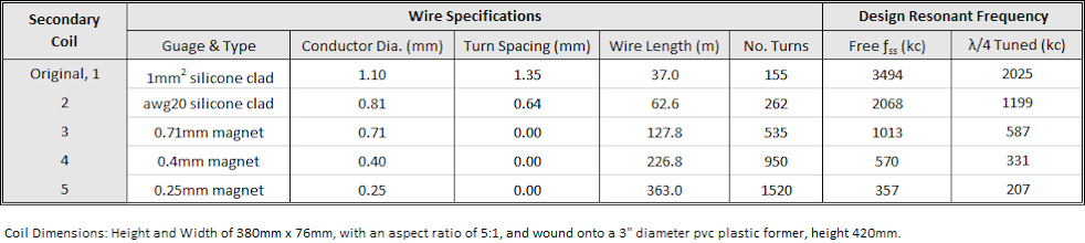
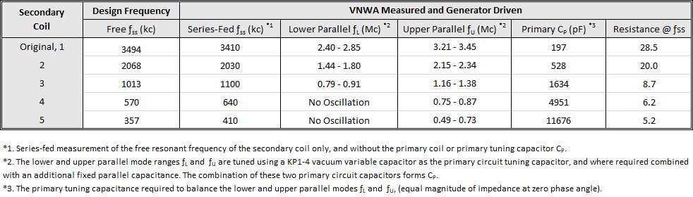
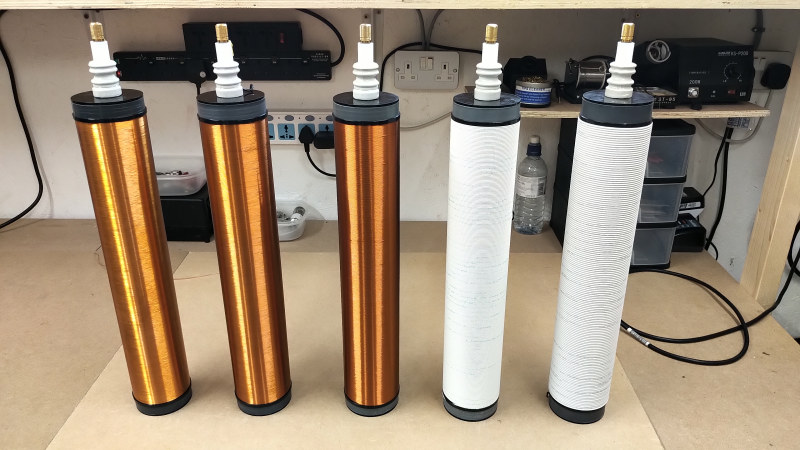
In this next experiment the exploration of vibration and frequency is extended across a much wider range by using a set of Tesla coils that are designed on the same geometry, with the same materials, but with different wire type and gauge, and hence the fundamental series resonant mode changes with the wire length. Originally five coils were designed and constructed, with series resonant mode frequencies of ƒSS ~ 357kc, 570kc, 1013kc, 2068kc, and the original at 3494kc. The general design characteristics of the coils, key measured, operating and tuning characteristics are summarised in figures 1 shown below, and explained in detail later in this post.

In practise, when using a self-tuned feedback oscillator as the generator, the lower frequency coils tend to preferentially oscillate at the 2nd or 3rd harmonic frequency around 1Mc, where the gain of the vacuum tube generator is higher, and the capacitive loading in the primary is lower. Increasing the tank capacitance to tune the fundamental of these lower frequency coils, significantly capacitively loads the vacuum tube generator reducing the Q of the system dramatically, and making it very difficult to oscillate in class-C mode. Ideally the two lowest frequency coils would be driven directly at the series resonant mode frequency ƒSS, however this drive strategy is not best suited to the scope of this experiment where variable frequency adjustment during operation is preferred. As a result of this, and without wanting to significantly change the generator and matching for this experiment from the previous one, the three upper frequency coils only are demonstrated in the video for this experiment. In practise that proved to be more than adequate to demonstrate the transition of the discharge form, from the fractal “fern” discharge, to the more standard “swords” form, which is commonly observed for a standard Tesla coil design when driven by a vacuum tube generator.

The video experiment demonstrates and includes aspects of the following:

1. Three secondary coils based on the same geometry, dimensions, and construction, with different wire gauge and hence wire length, producing a different fundamental series resonant frequency in each secondary coil.

2. A standard vacuum tube Tesla coil generator (VTTC), operated in CW mode using a pair of 833C vacuum tubes (VT) arranged in parallel as a tuneable class-C Armstrong oscillator.

3. The tube power supply (HV & Plate) configured for 2 series transformers with a nominal output of 4.2kV @ 0.8A, 3.3kVA, HV bridge rectified, and with 25nF 25kV blocking capacitor at the output, and operated up to 3kW line input power.

4. Secondary coils with nominal fundamental series resonant frequencies of ~ 3.5Mc, 2.0Mc, and 1Mc, could be easily exchanged, tuned, and matched to the VT generator.

5. The 3.5Mc coil operated over a range of 2.4-3.3Mc, shows the fractal “fern” discharge over the entire frequency band. A tighter and denser fractal “fern” was observed across the upper parallel mode.

6. The 2.0Mc coil operated over a range from 1.5-2.3Mc, shows the fractal “fern” discharge at the upper parallel mode, and the “swords” discharge at the lower parallel mode.

7. The 1.0Mc coil operated over a range from 970kc-1.4Mc, shows the “swords” discharge over the entire frequency band.

8. The transition from fractal “fern” to “swords” occurs between 1.8-2.0Mc, where the “sword” discharge retains slight curvature until frequencies < 1.5Mc.

9. Conjecture that the variation of discharge form may result from the changing vibrational qualities within the relationship between the dielectric and magnetic fields of induction at different frequencies, and hence part of the underlying principles and mechanisms within the Wheelwork of Nature.

Principle of Operation and Construction of the Experimental System

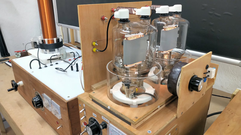
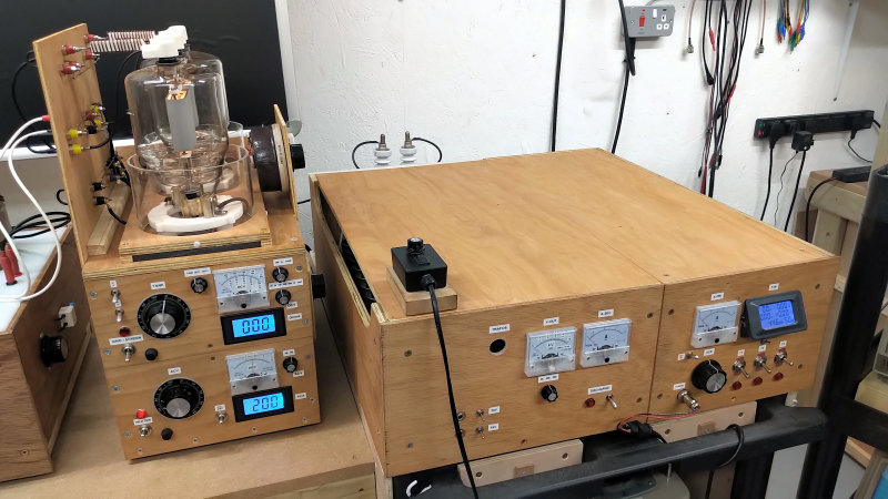
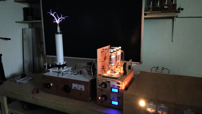
The experimental apparatus uses the same high voltage plate tube supply from the pervious experiment, configured in the same way with two series transformers, bridge rectified, and with a 25nF blocking capacitor at the generator output to protect the semiconductors of the bridge rectifier. The design, construction, and operation of this high voltage tube supply is covered here Tube Power Supply – High Voltage & Plate. The generator itself uses the dual 833C tube board with the tube supply heater unit as an class-C Armstrong oscillator, both of which were used in the variation experiments in the first part of this series, and are covered in detail in Tube Power Supply – Heater, Grid & Screen. The dual 833C tubes proved to be more flexible over a wider frequency band than the single GU5B based generator used in the primary Wheelwork of Nature experiment. The principle of operation of the generator, setup, operating characteristics, and schematic are covered in detail in the original post here The Wheelwork of Nature – Fractal “Fern” Discharges.

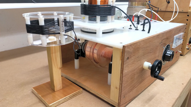
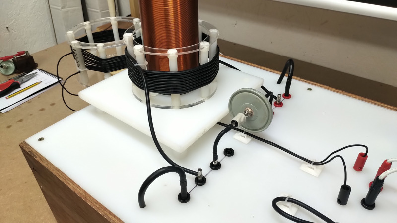
The feedback coil for the Armstrong oscillator now has variable windings, and is positioned offset from the secondary coil. The variable turn geometry of the feedback coil facilitates more accurate and optimal tuning of the generator based on the secondary coil used, and the lower or upper parallel mode being explored. Too much feedback to the generator will distort the drive waveform away from a clean sinusoidal, and too little feedback makes the oscillation unstable, and with a reduced gain in the generator. The optimal adjustment was to establish oscillation with the maximum number of turns on the feedback coil which produced a clean sinusoidal oscillation in the primary tank circuit. The number of turns varied for each secondary coil, and for the upper or lower parallel mode for each coil. With the correct number of turns set on the feedback coil, the generator match to the experiment was fine adjusted using the grid bias rheostat to produce maximum output from the secondary, with minimum average grid current.

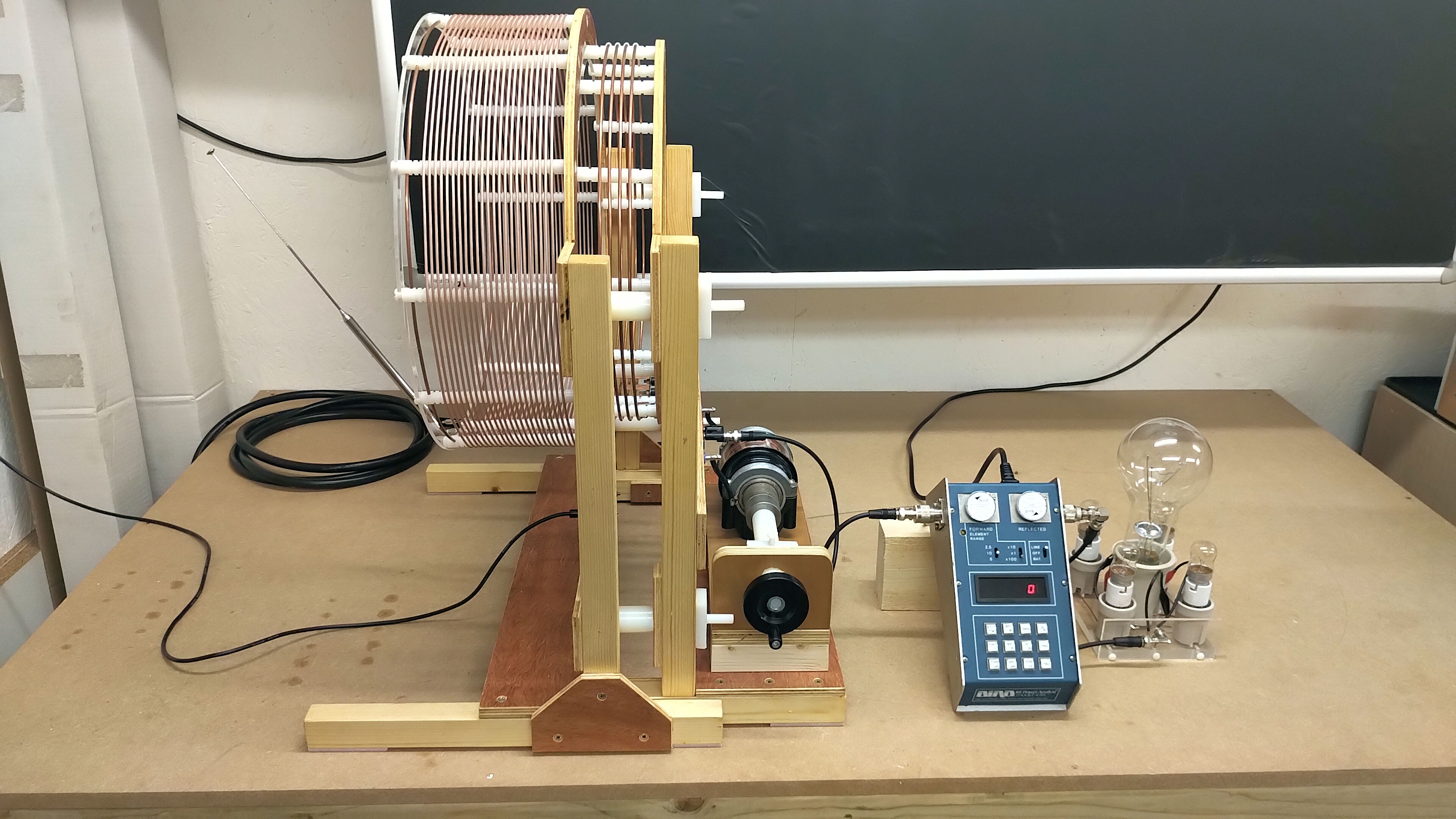
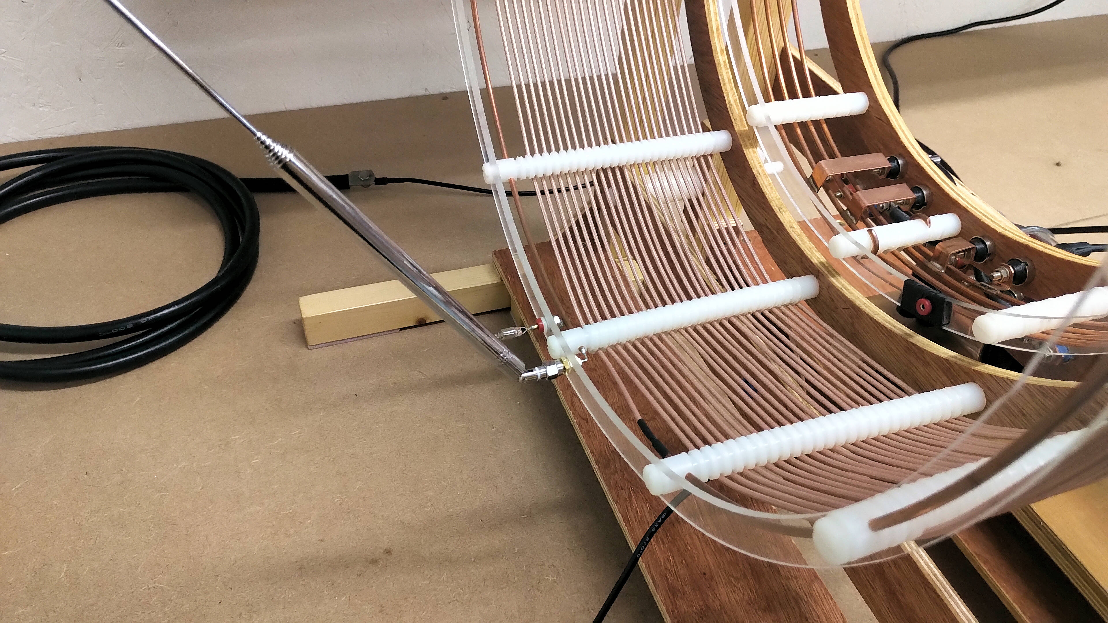
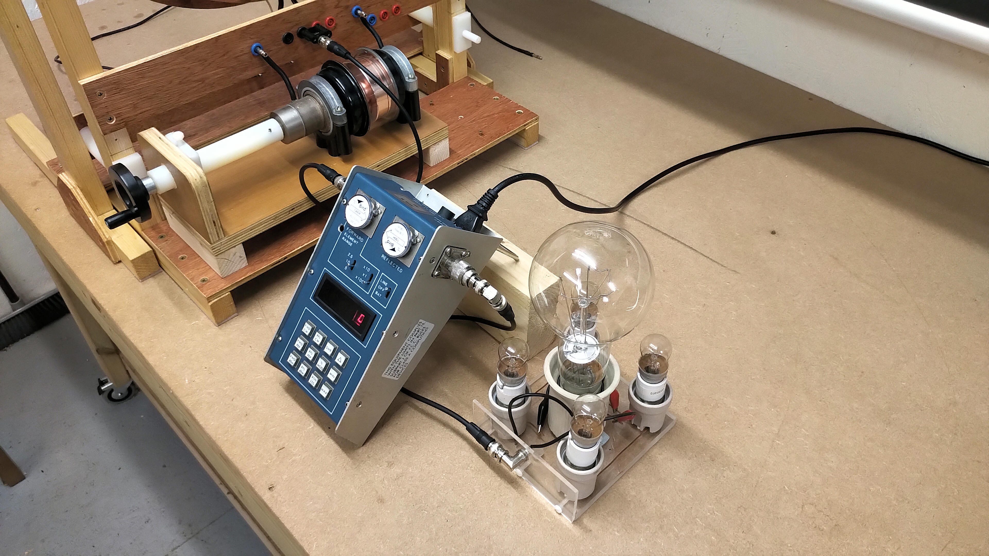
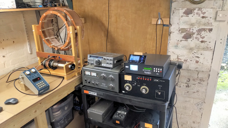
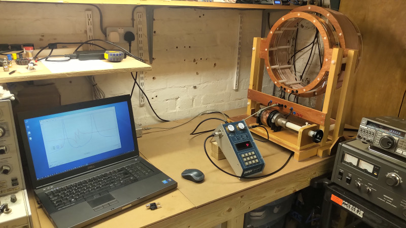
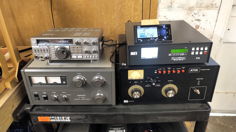
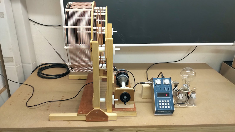
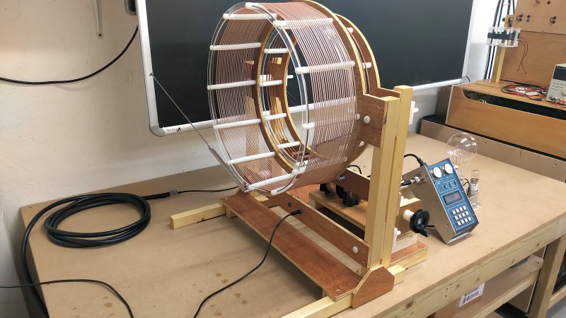
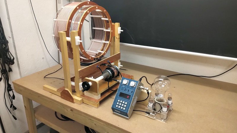
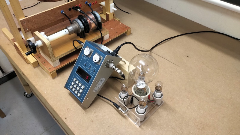
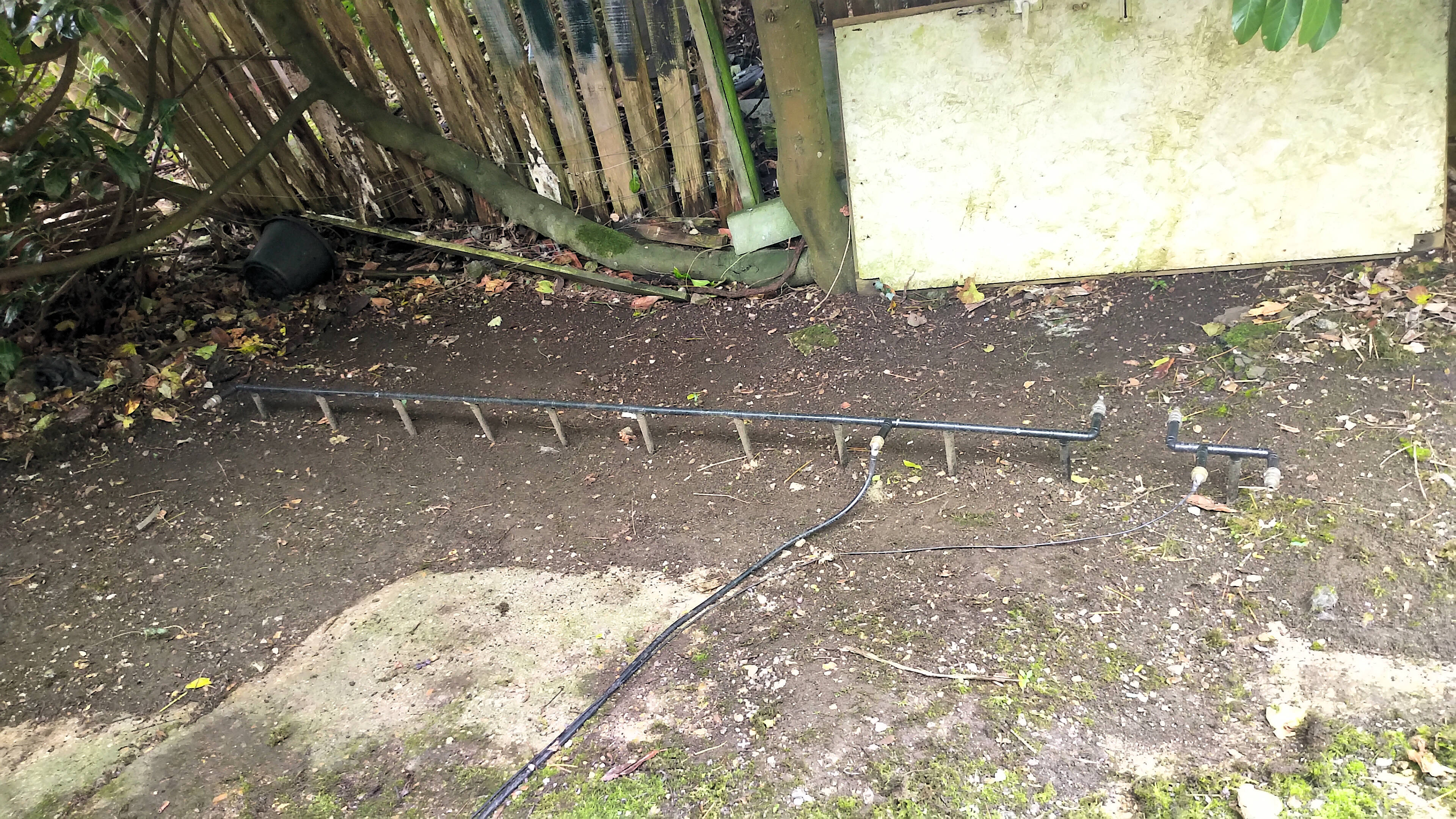
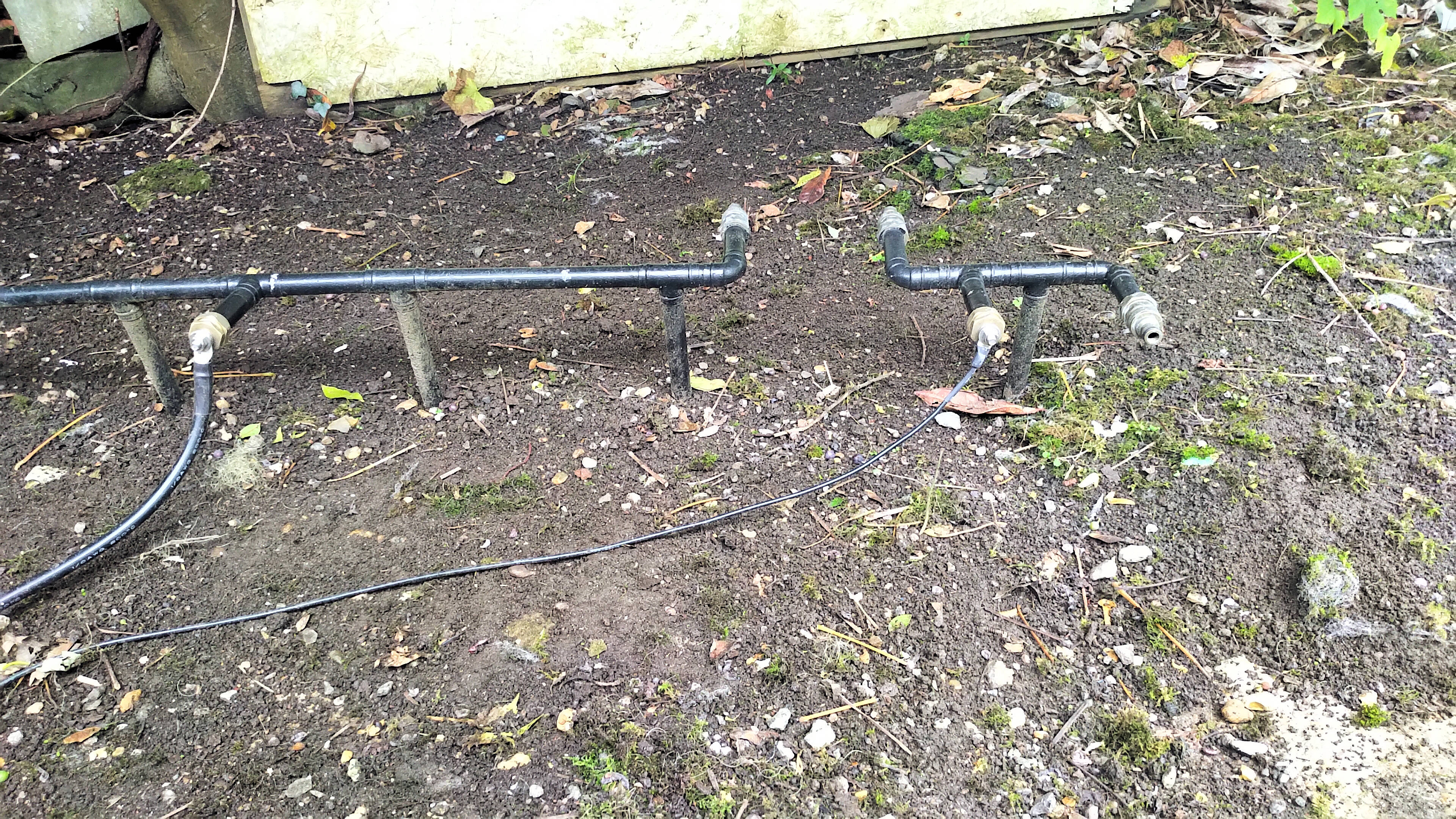
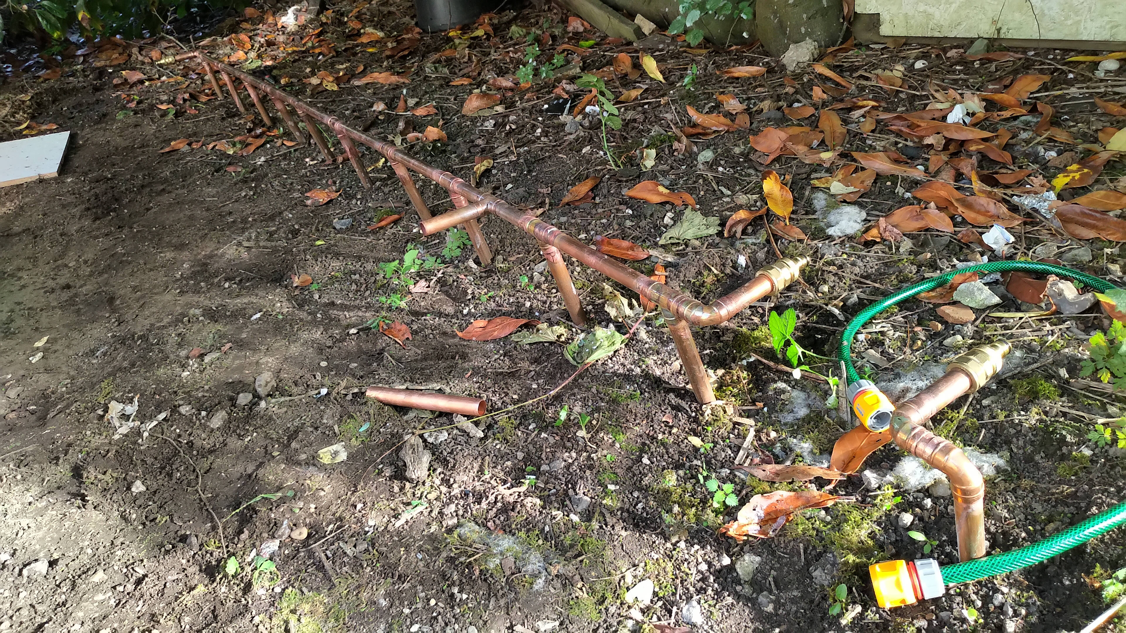
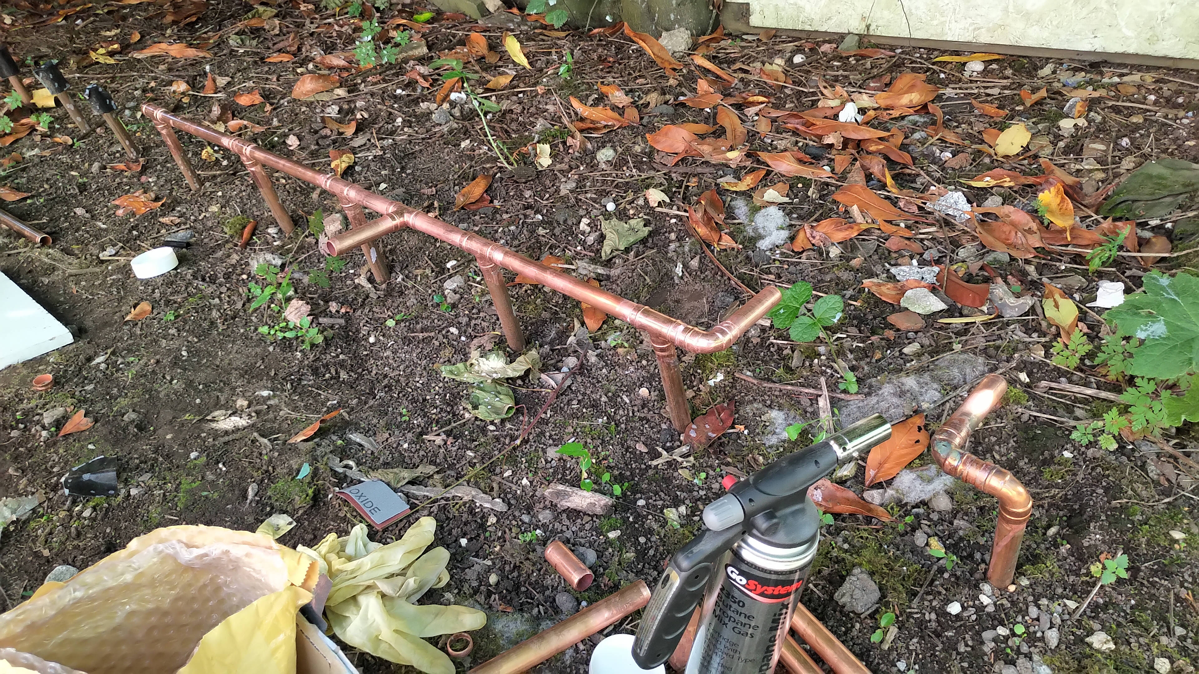
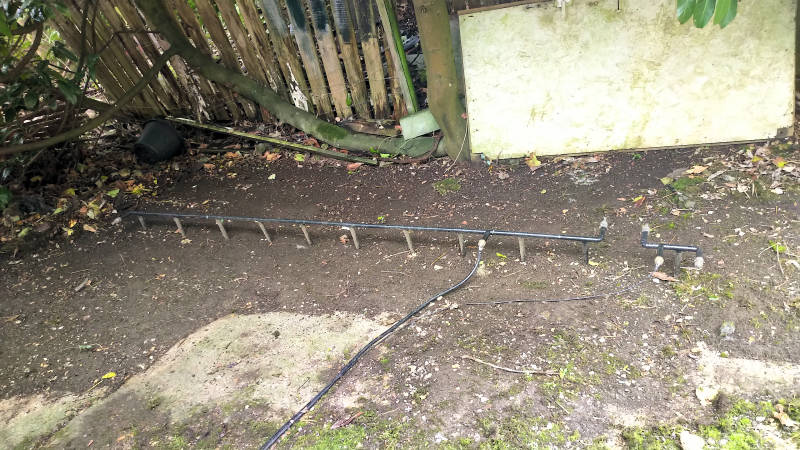
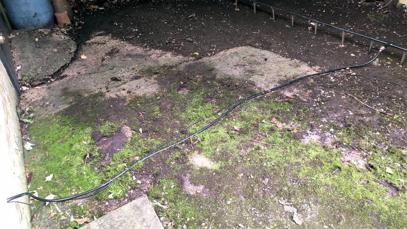
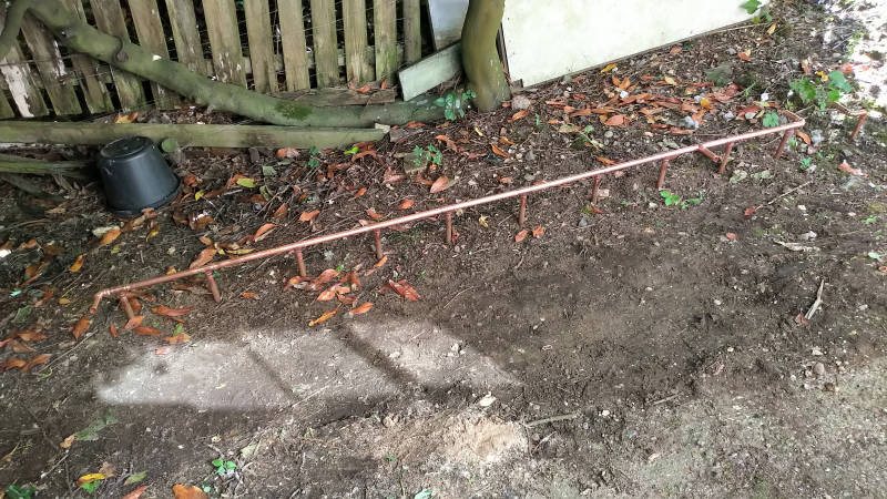
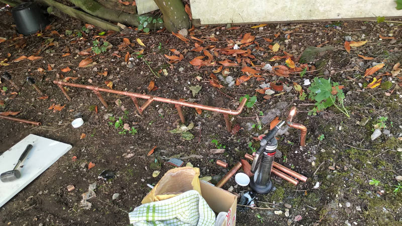
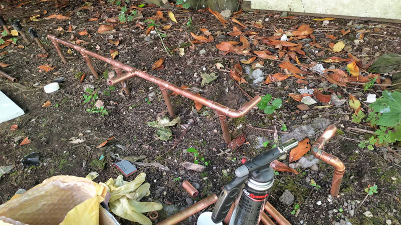
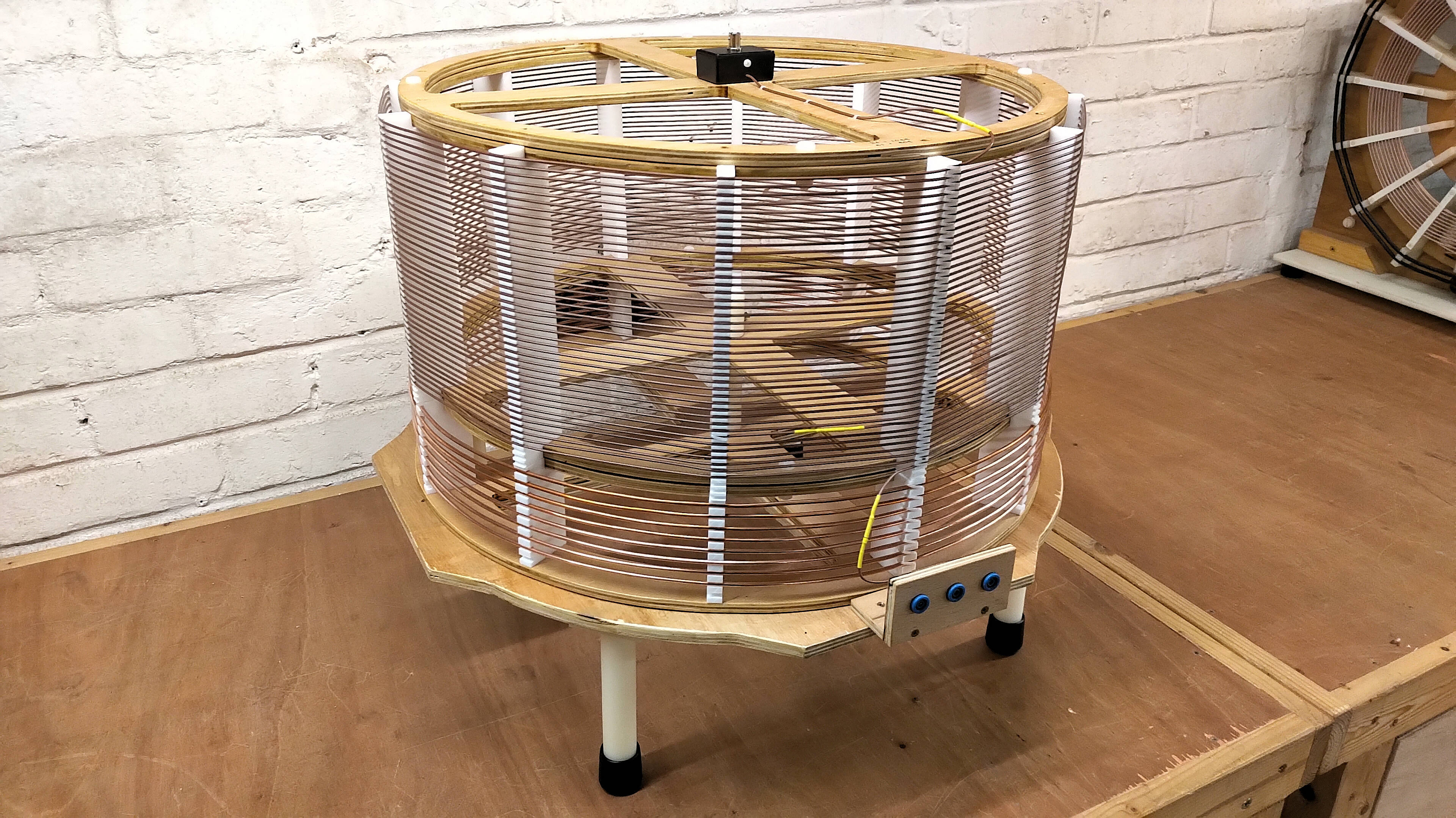
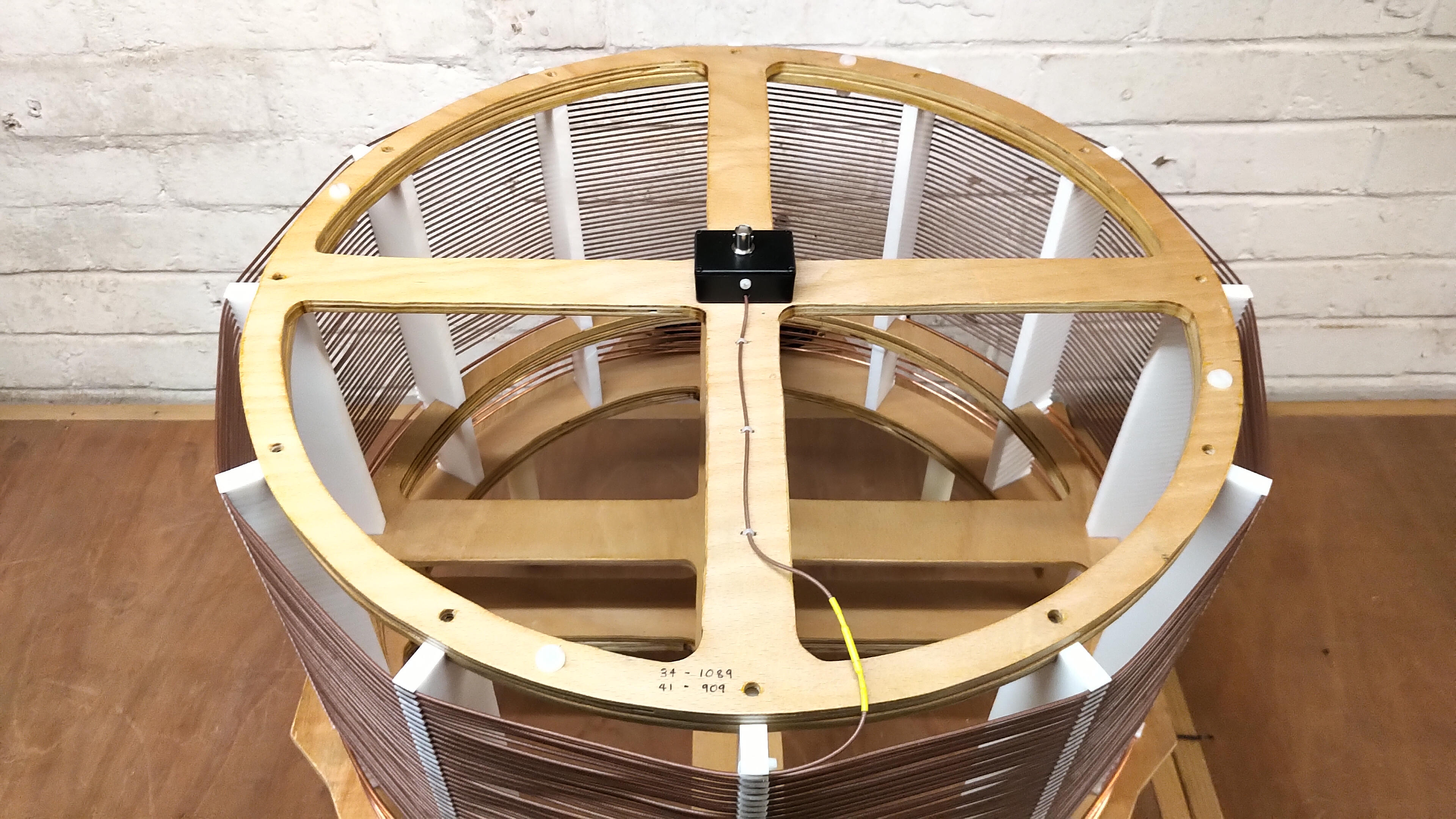
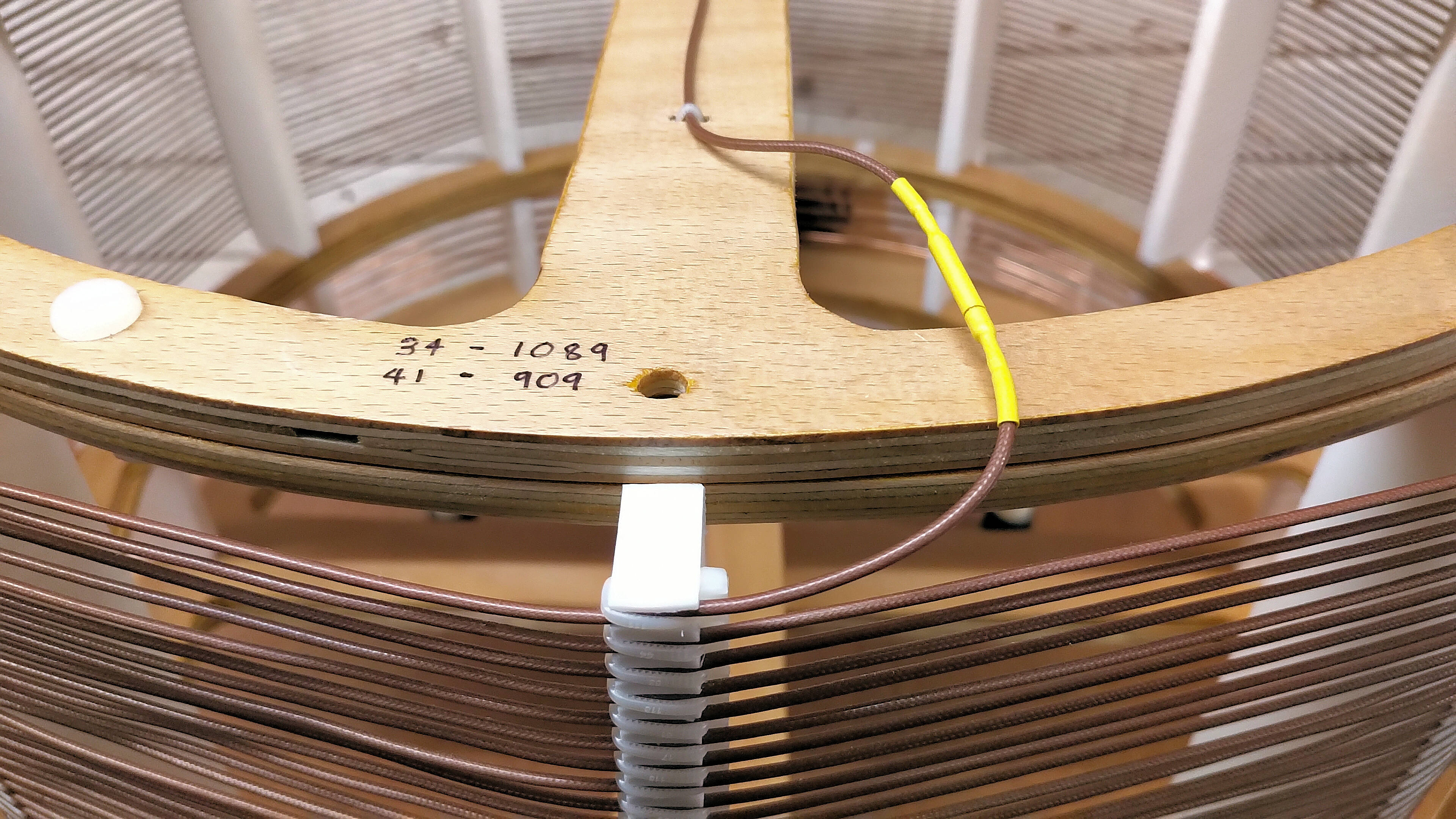
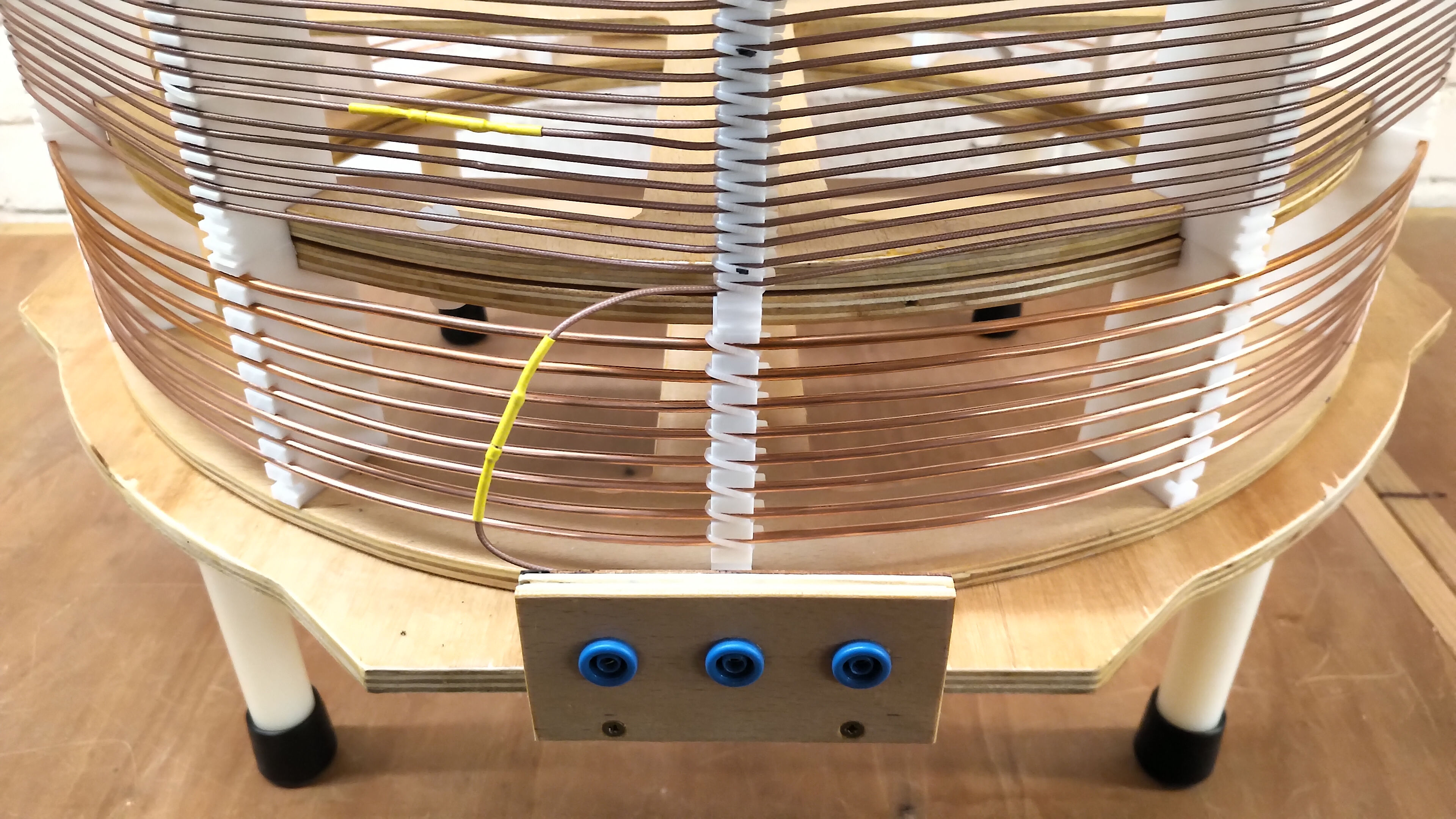
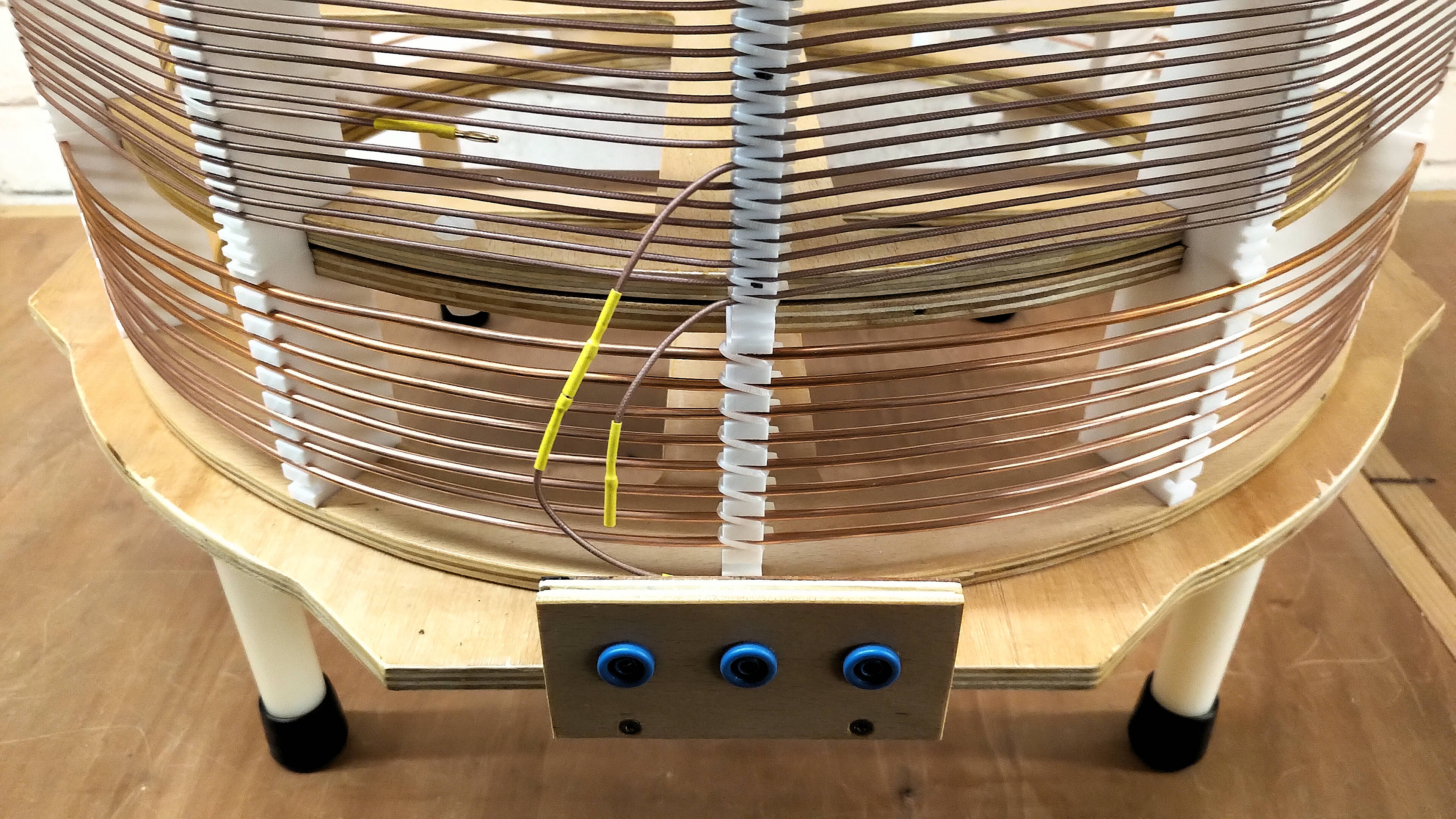
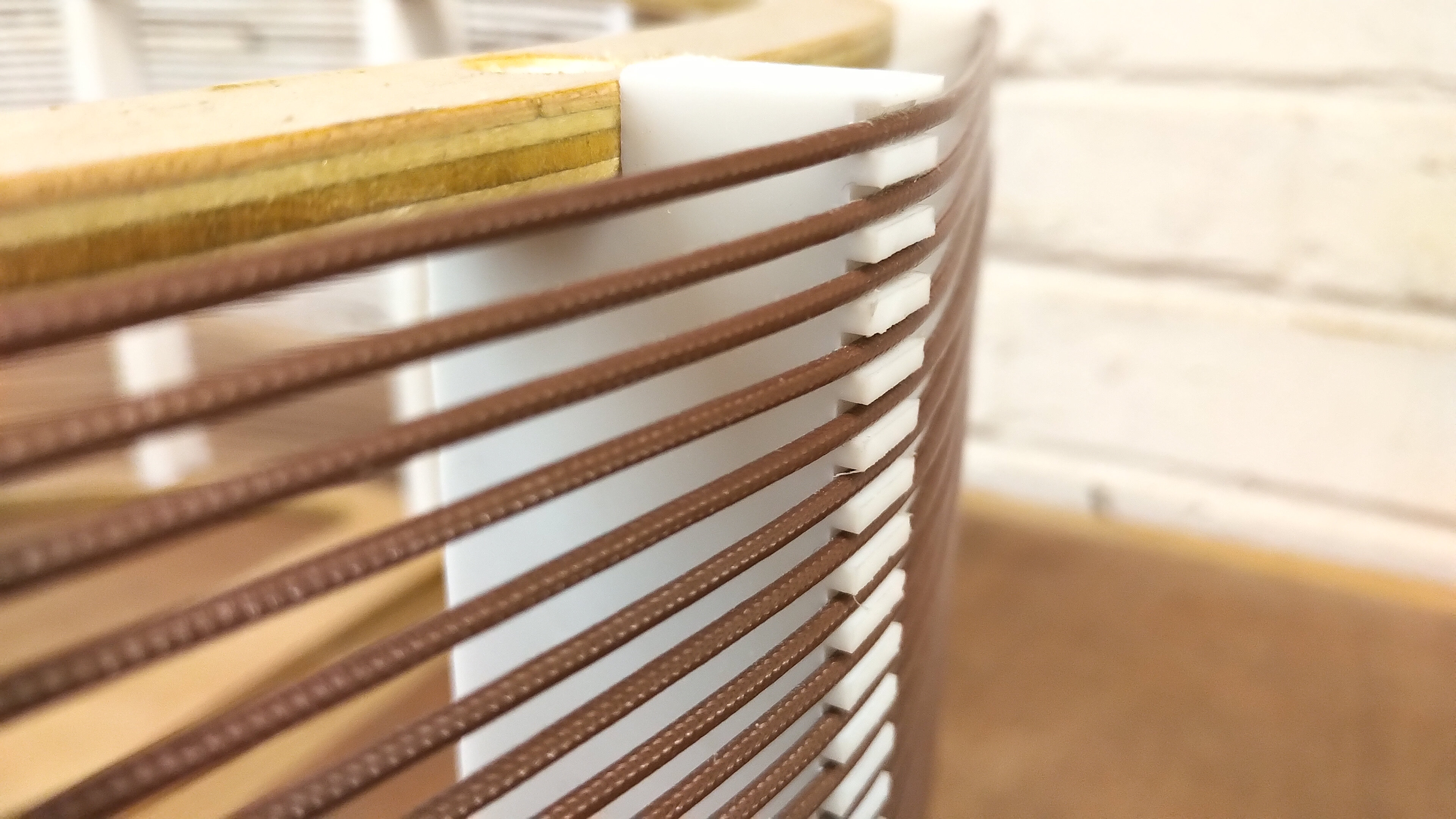
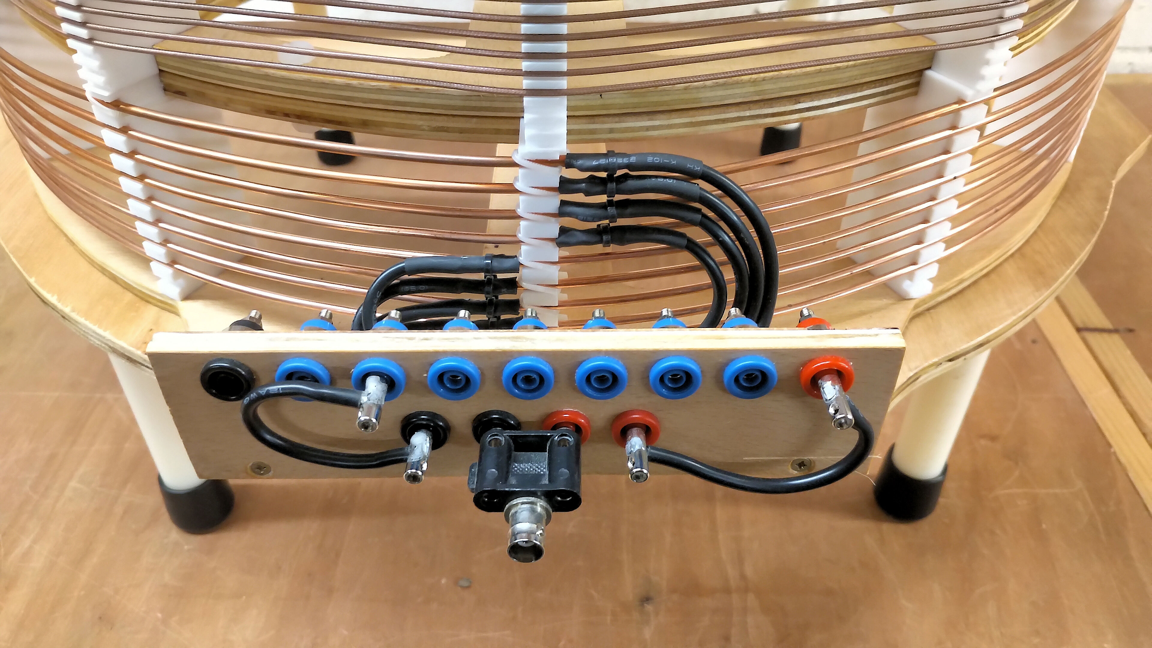
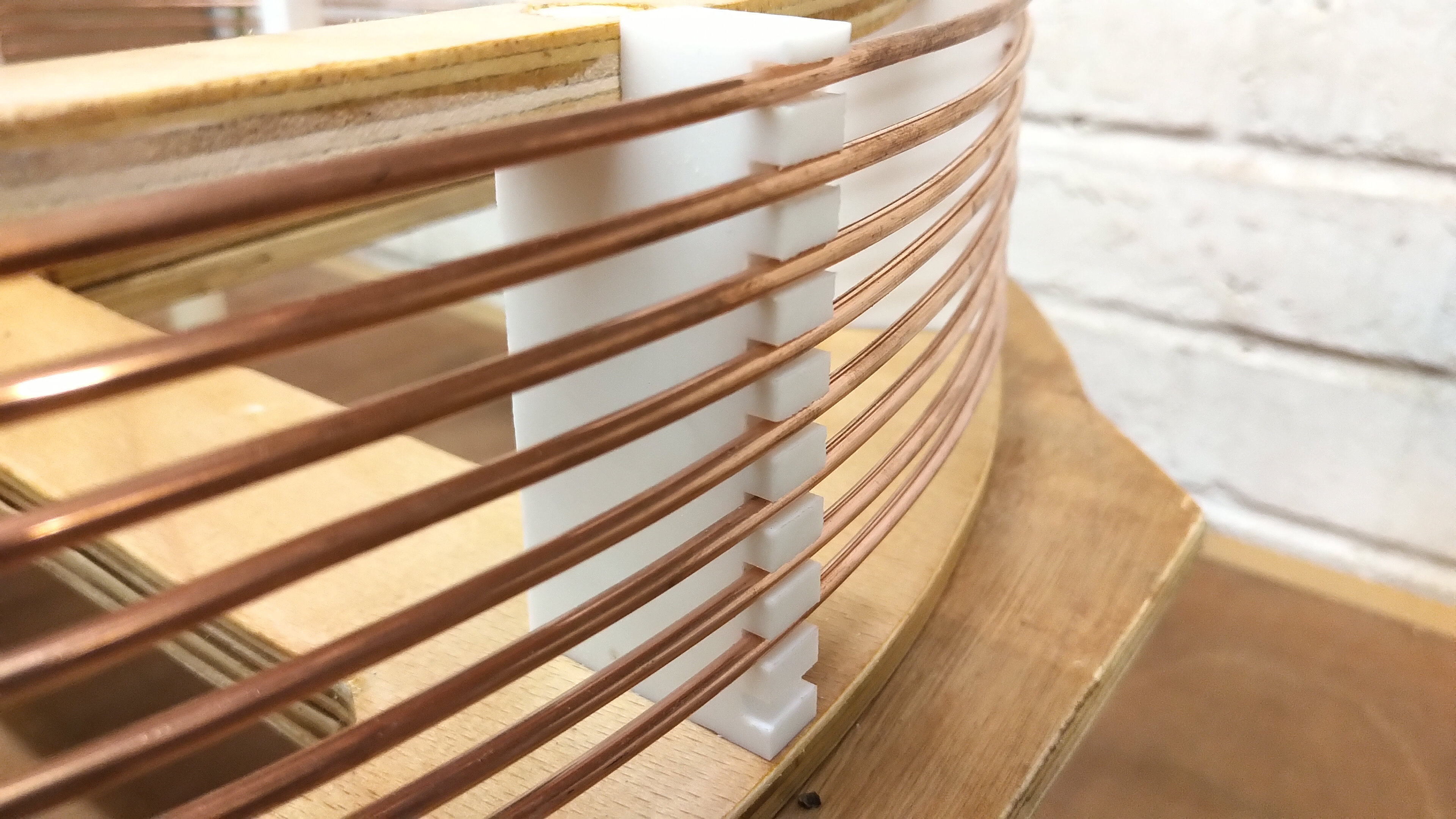
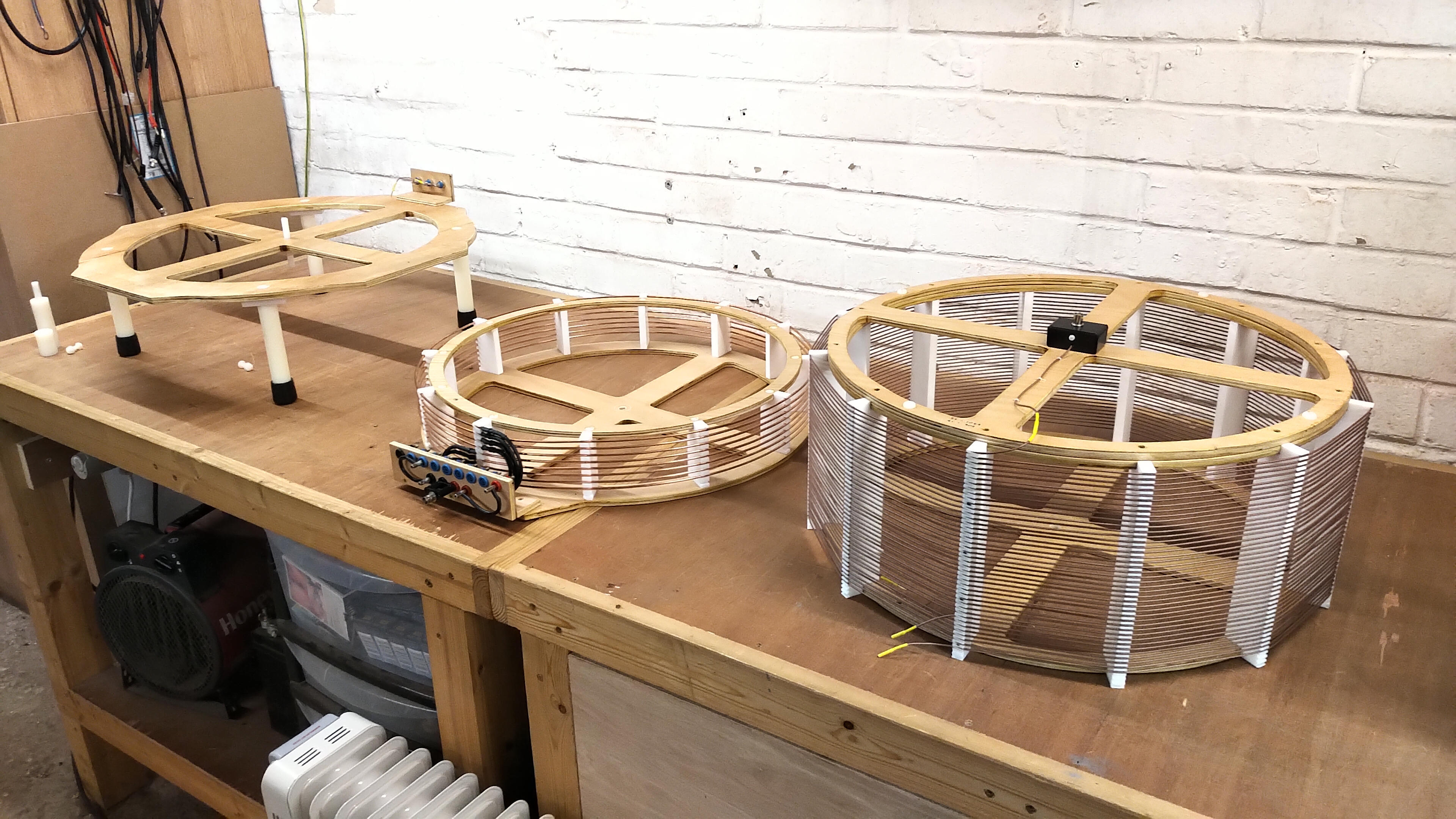
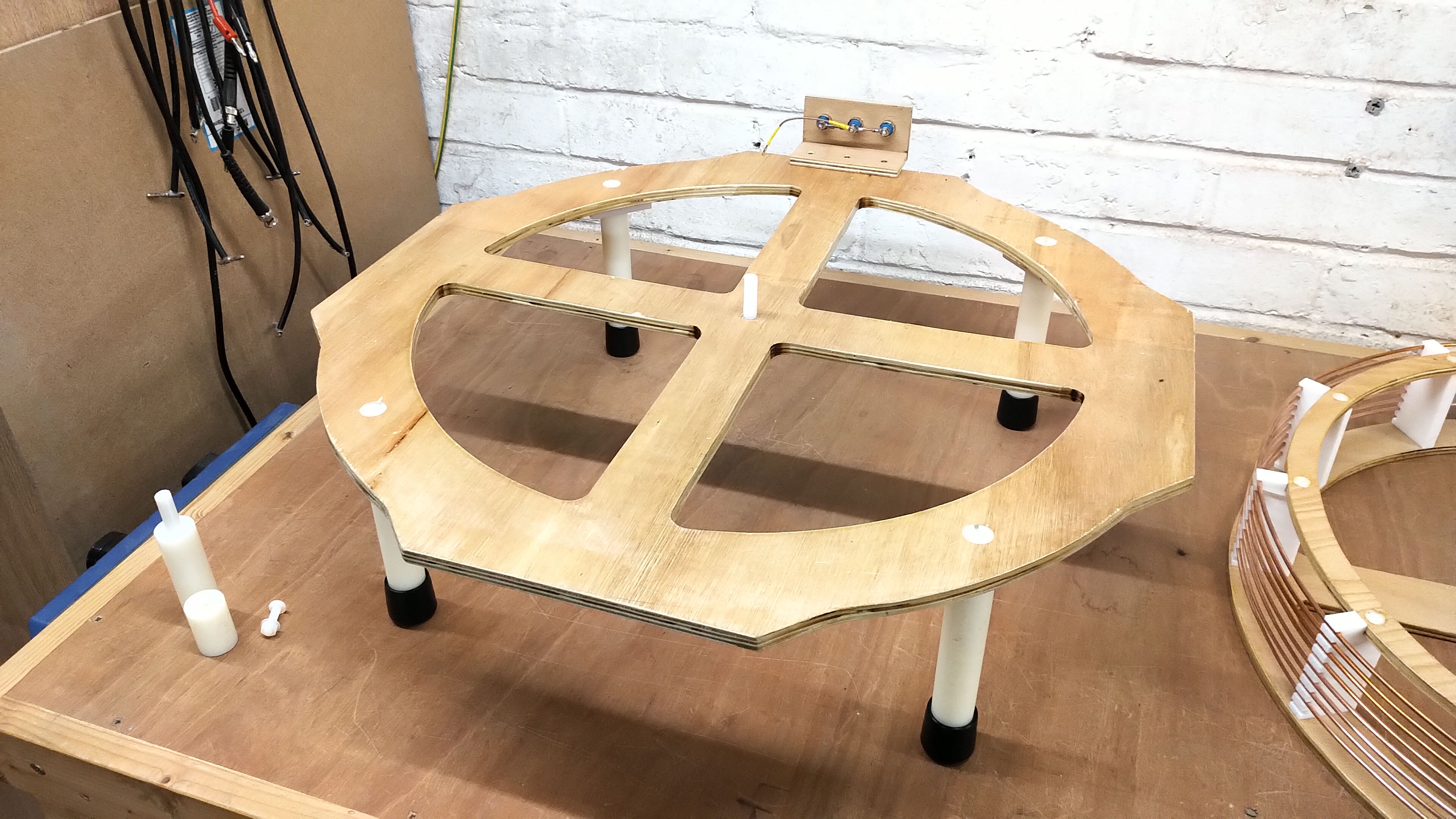
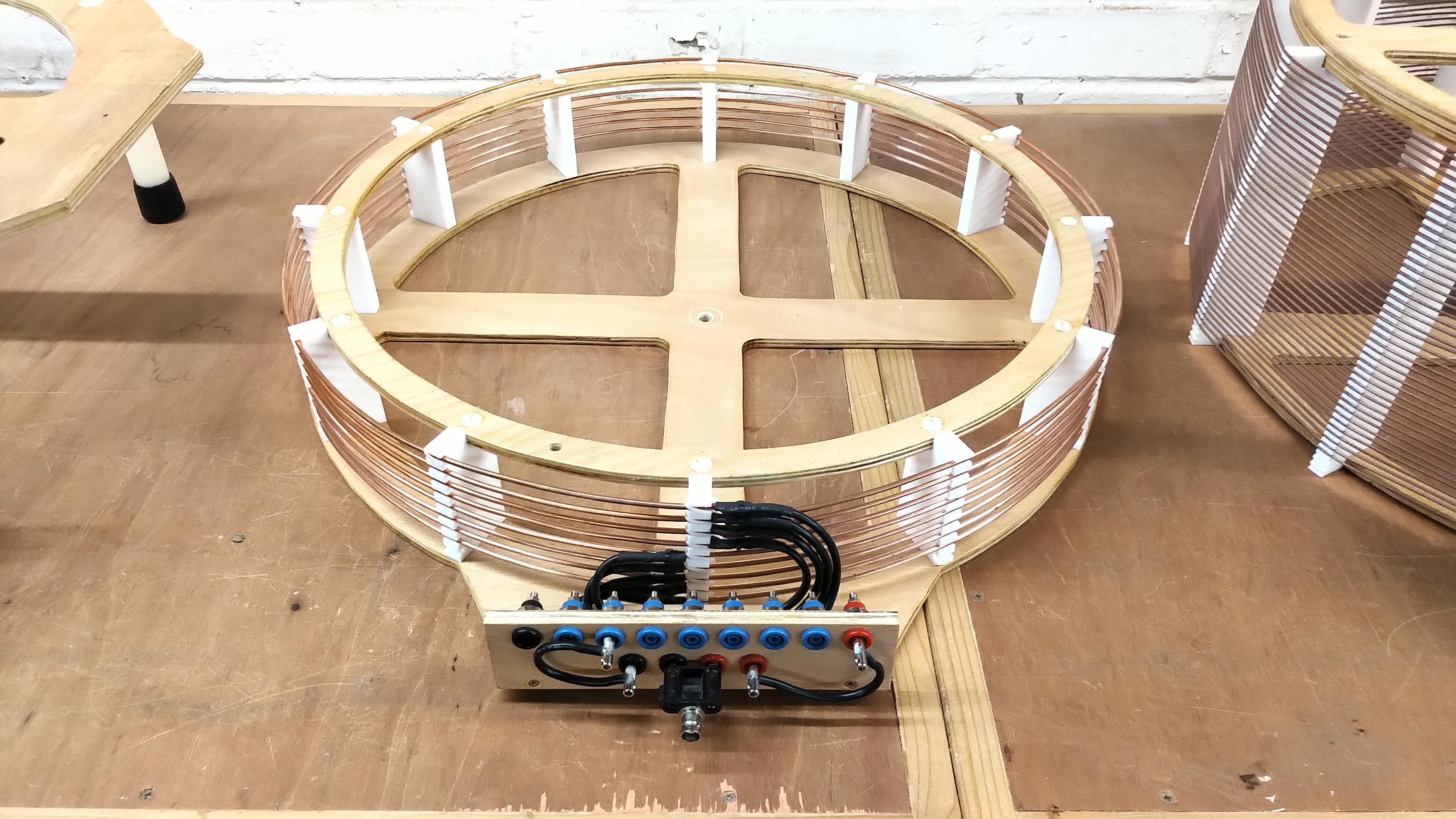
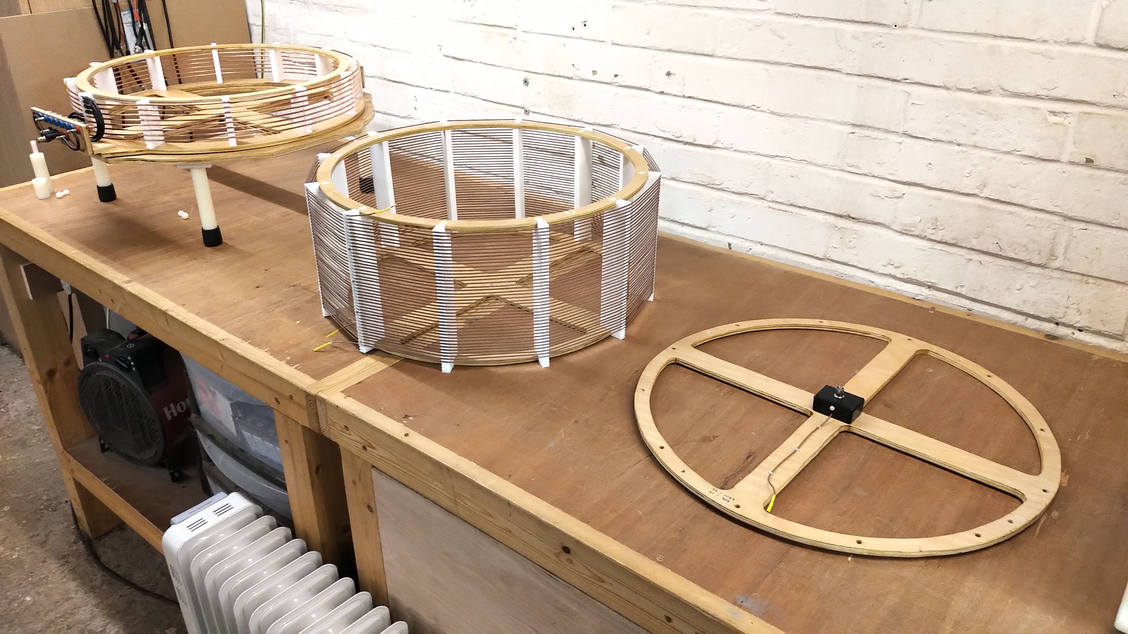
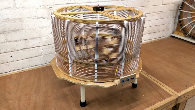
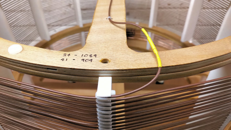
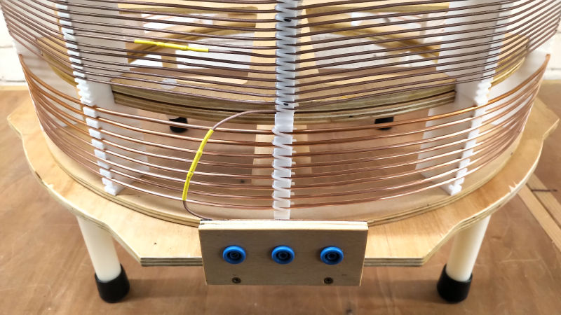
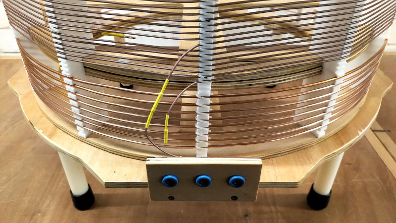
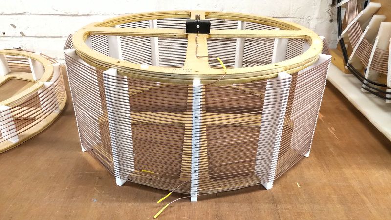
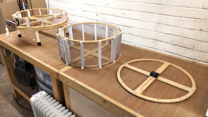
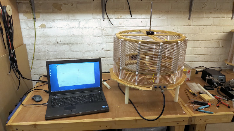
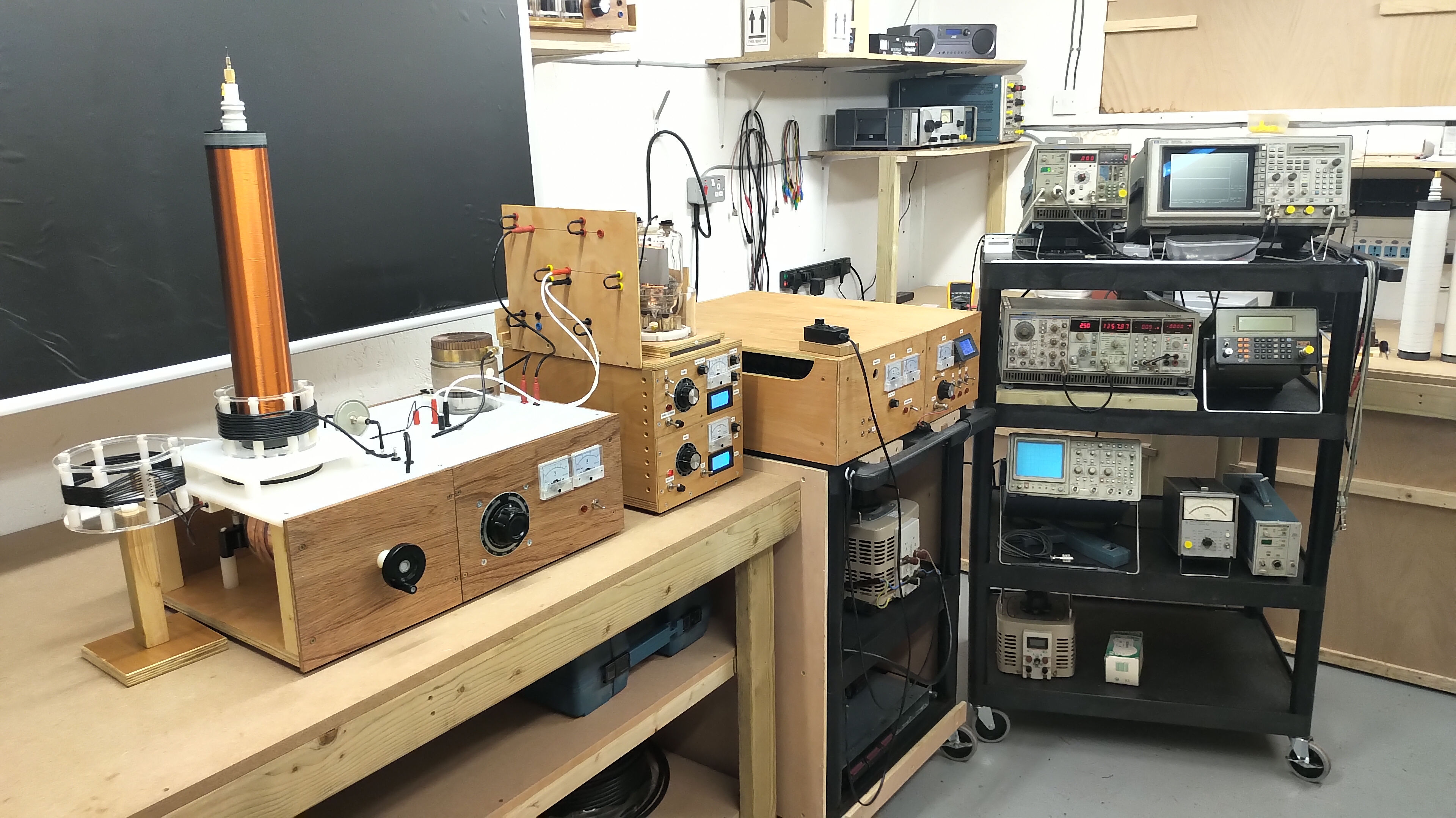
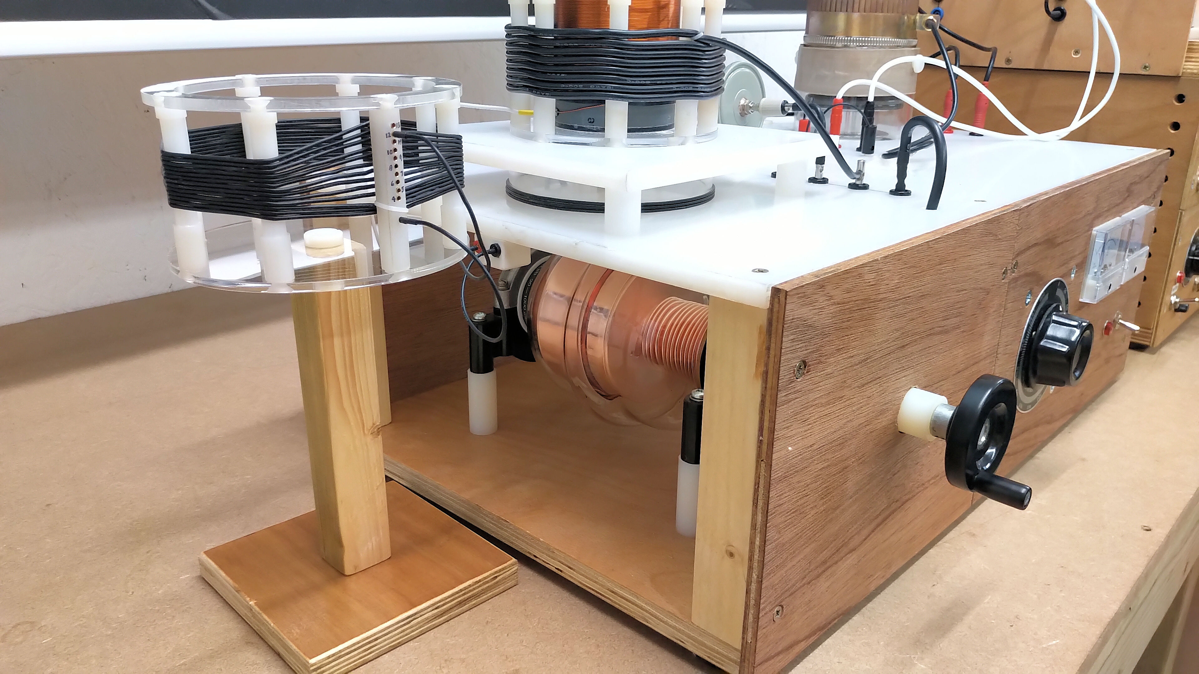
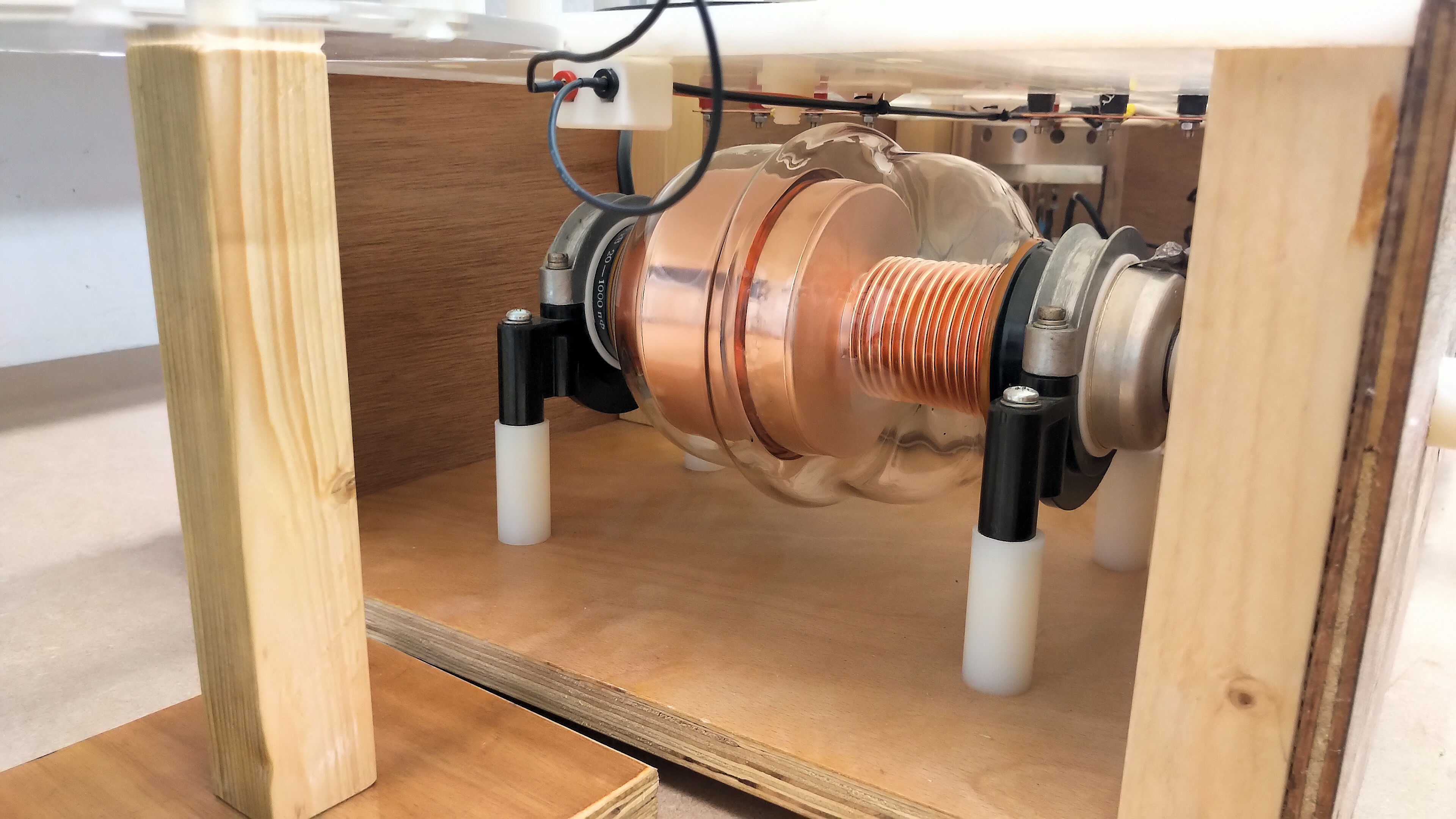
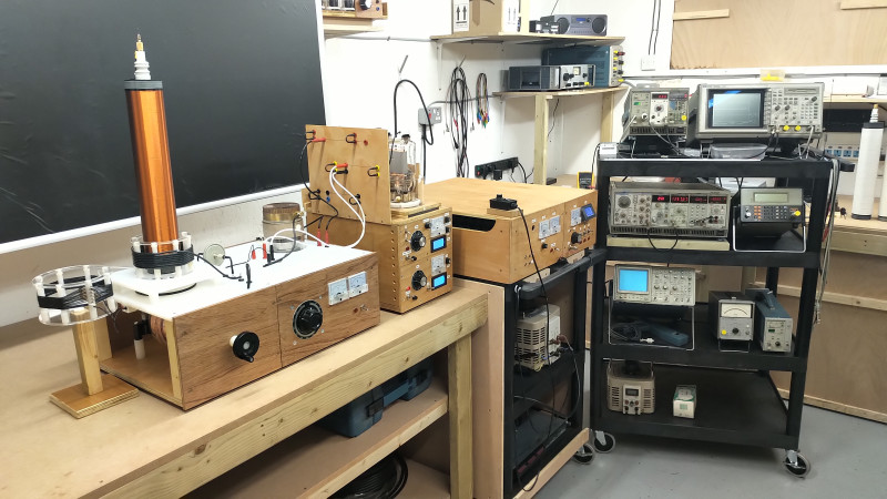
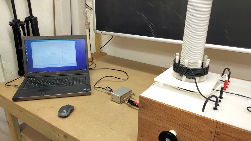
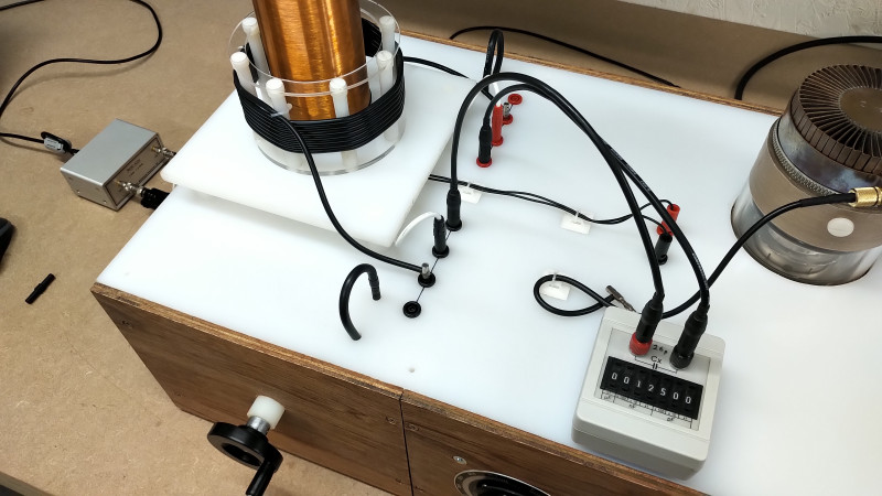
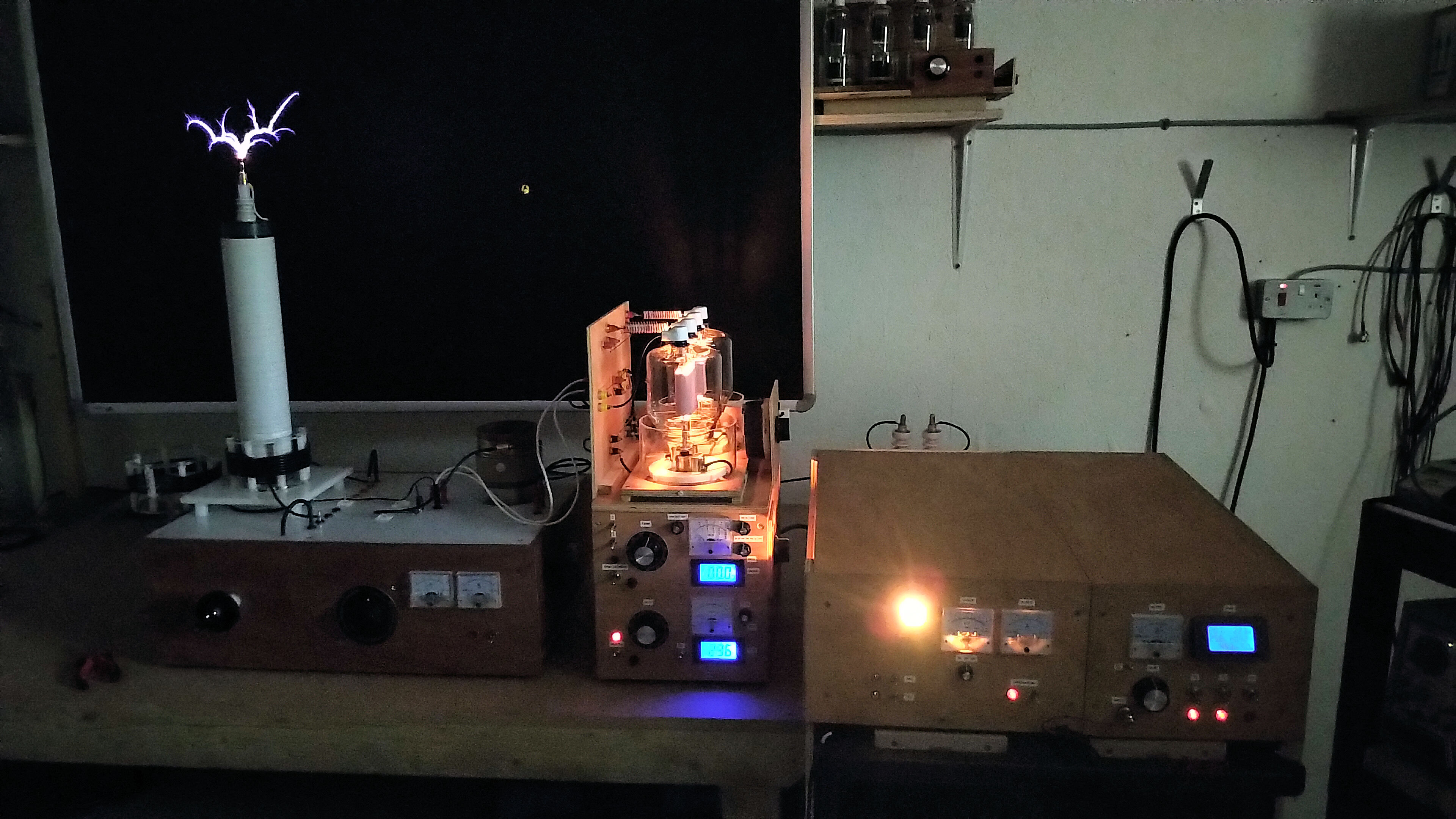
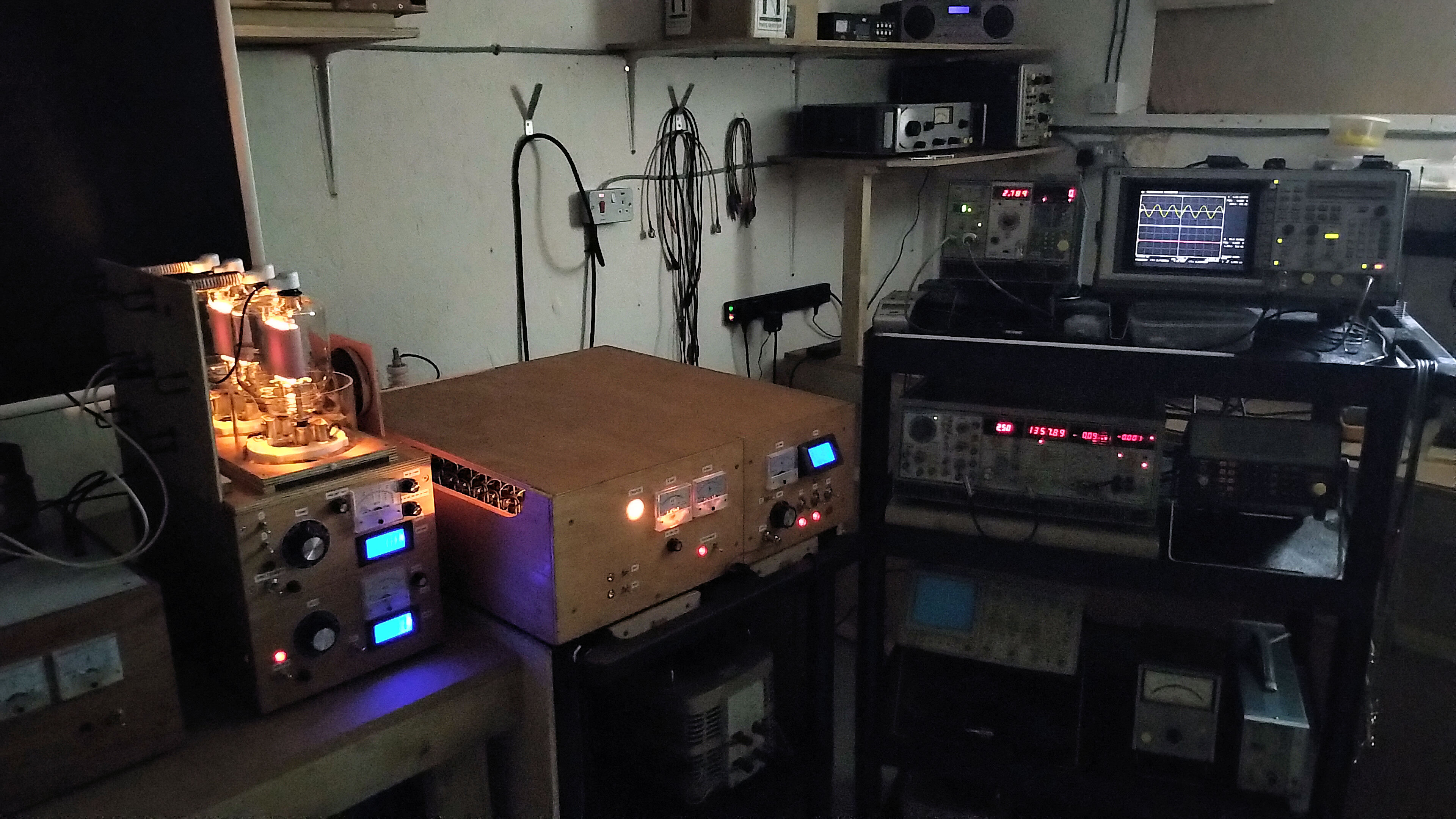
Figures 2 below show a range of pictures of the experimental apparatus used in the video experiment, along with the measurement equipment, and some of the key construction details that vary from the original experiment.

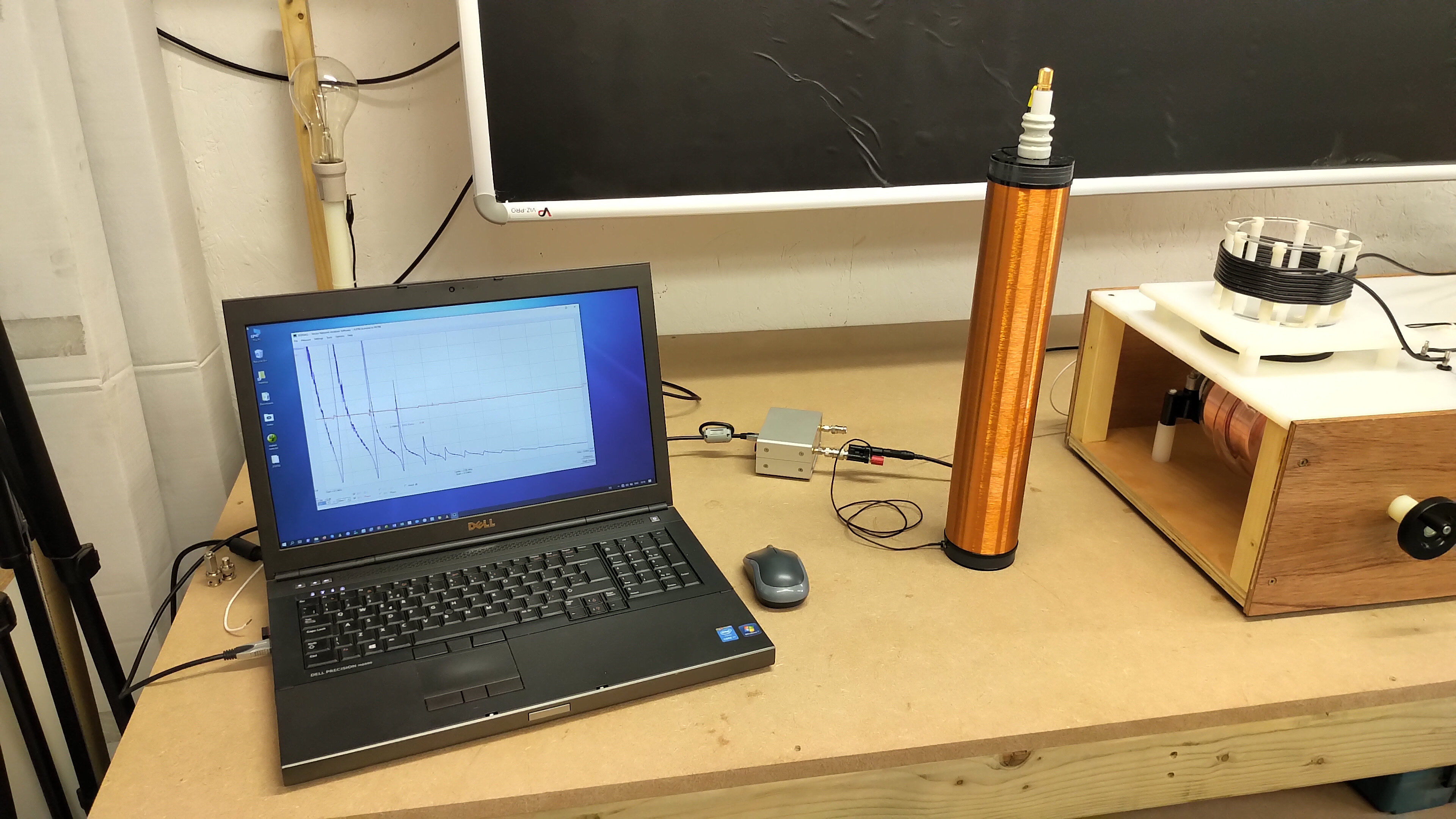
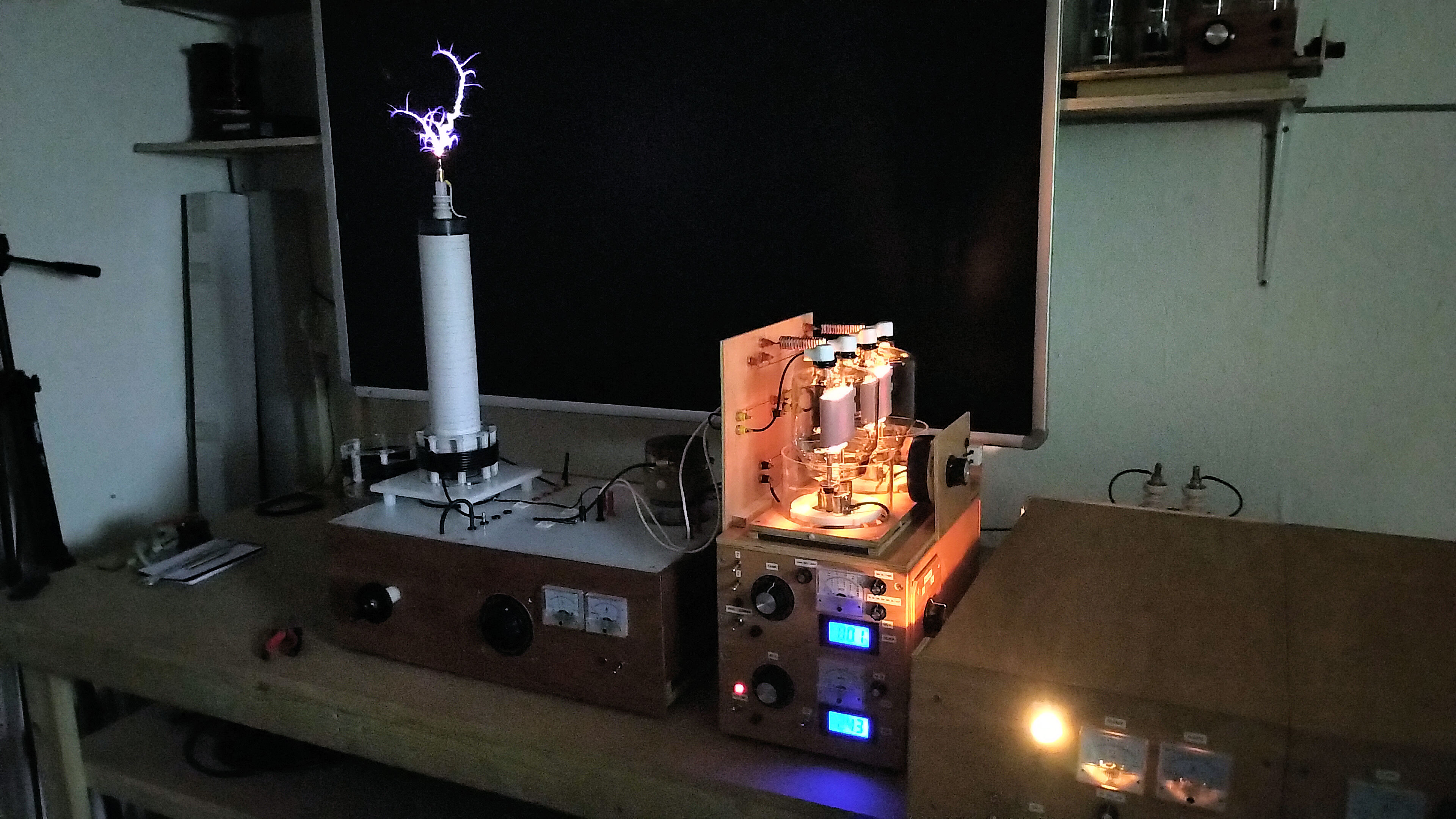
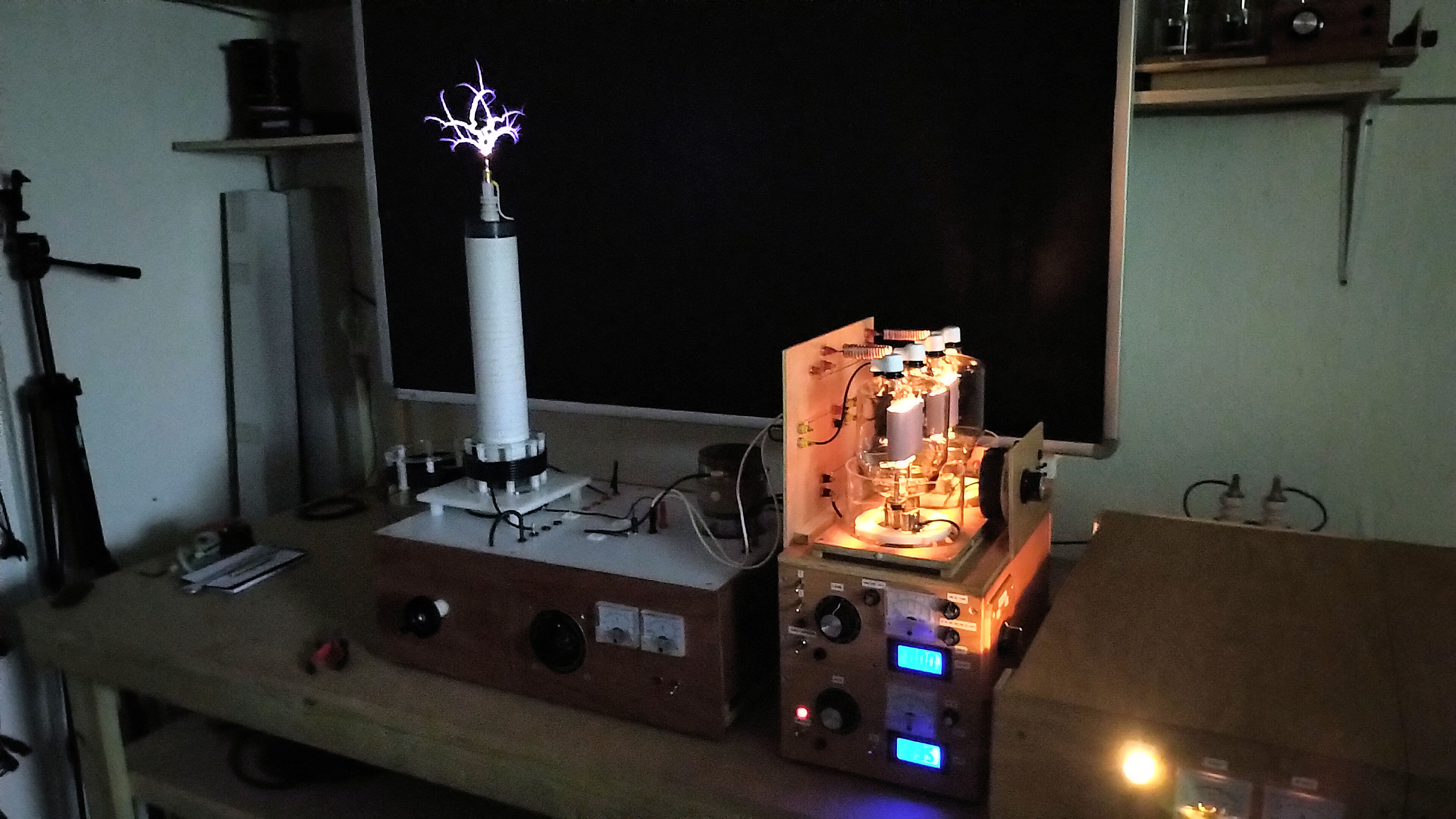
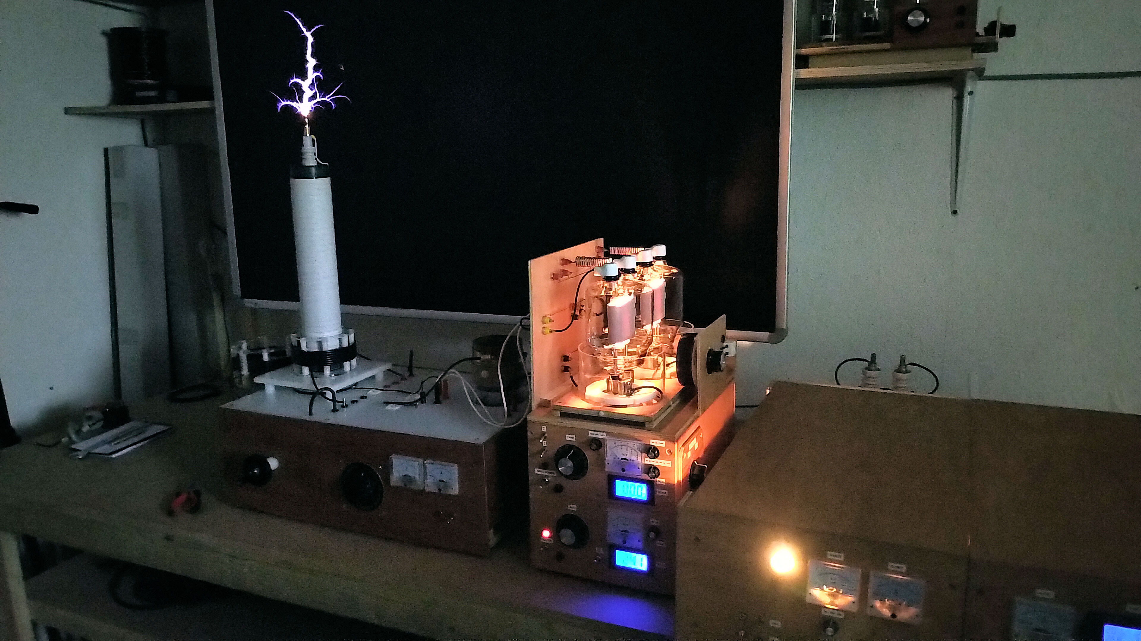
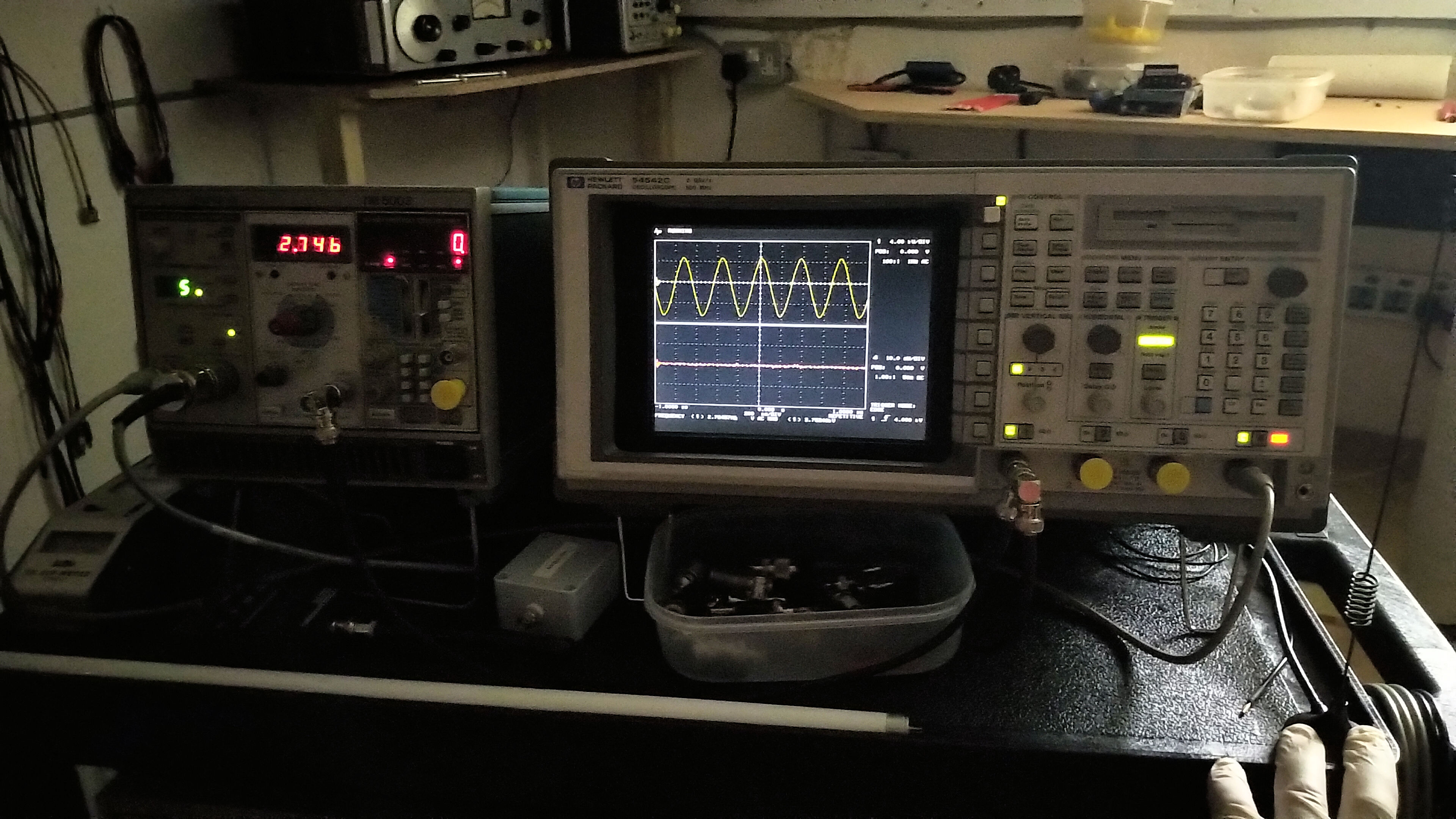
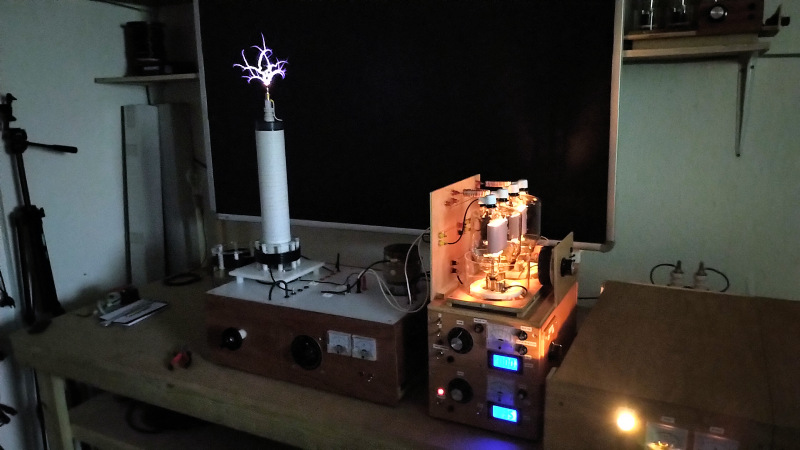
Figures 3 below show some of the operation highlights during the experimental running, and the typical output from the measurement equipment, including generator driving frequency and waveform.

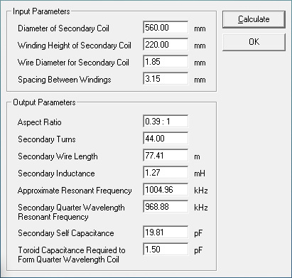
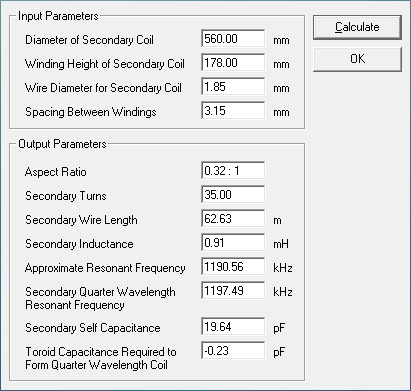
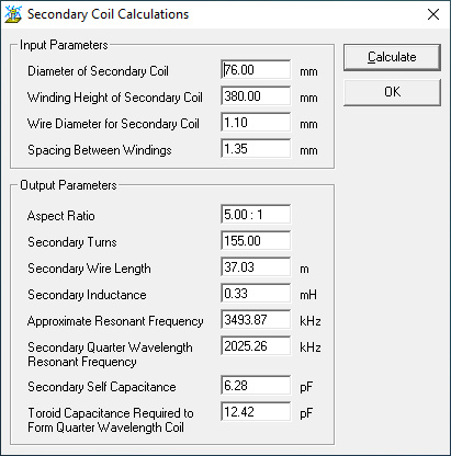
Again Tccad 2.0 was used for a rapid and approximate indication of the electrical and resonant characteristics of the secondary coils, the detailed results of which are shown below in figure 4. The wire selected for coil 1 and 2 is a good quality silicone coated multi-stranded conductor, the silicone coating being very good both thermally, and as an insulator to prevent breakouts and breakdown from the upper turns of the coil to the lower ones. For secondary coils 3, 4, and 5, a good quality polyester-polyamide coated magnet wire was used, with the final wound coil being further coated with high-temperature lacquer. The final lacquer coating is used to keep the windings in place, and add some additional breakdown insulation protection.

Small Signal AC Input Impedance Measurements

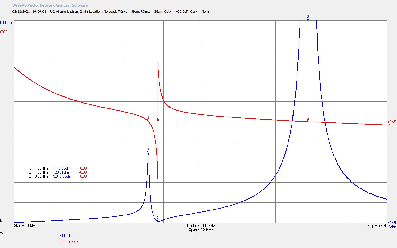
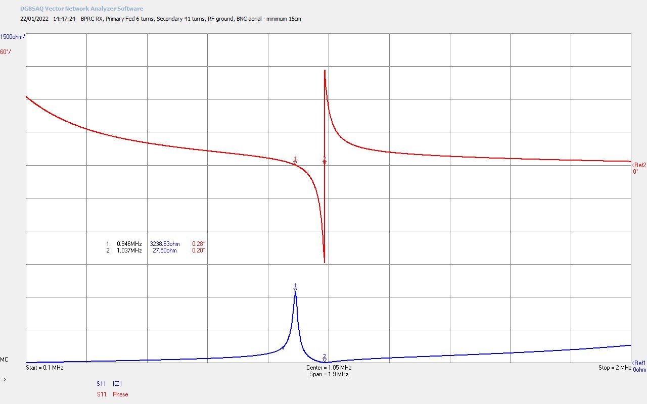
The small signal ac input impedance Z11 for each Tesla coil was measured directly using an SDR-Kits VNWA vector network analyser, as used on many experimental pages on this site. Figures 5 show the series-fed free resonant characteristics of the five Tesla secondary coils.

To view the large images in a new window whilst reading the explanations click on the figure numbers below.

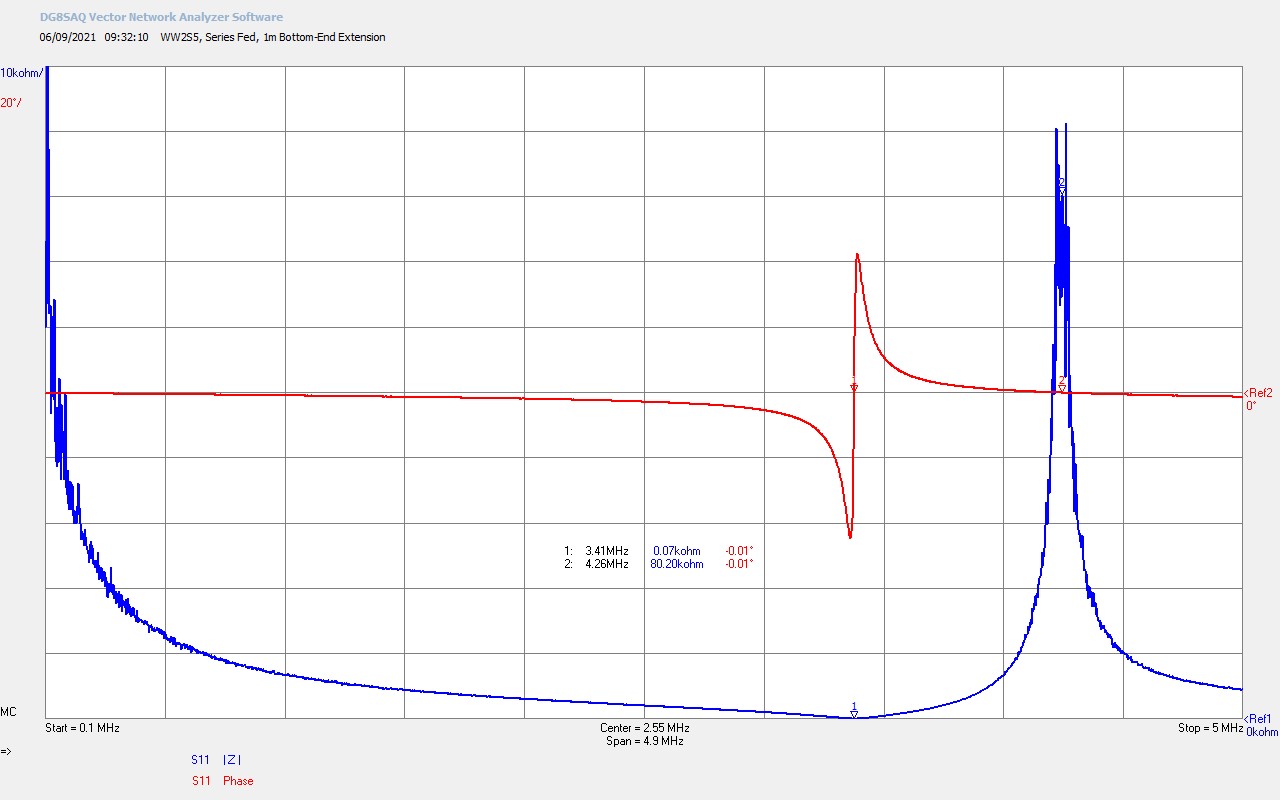
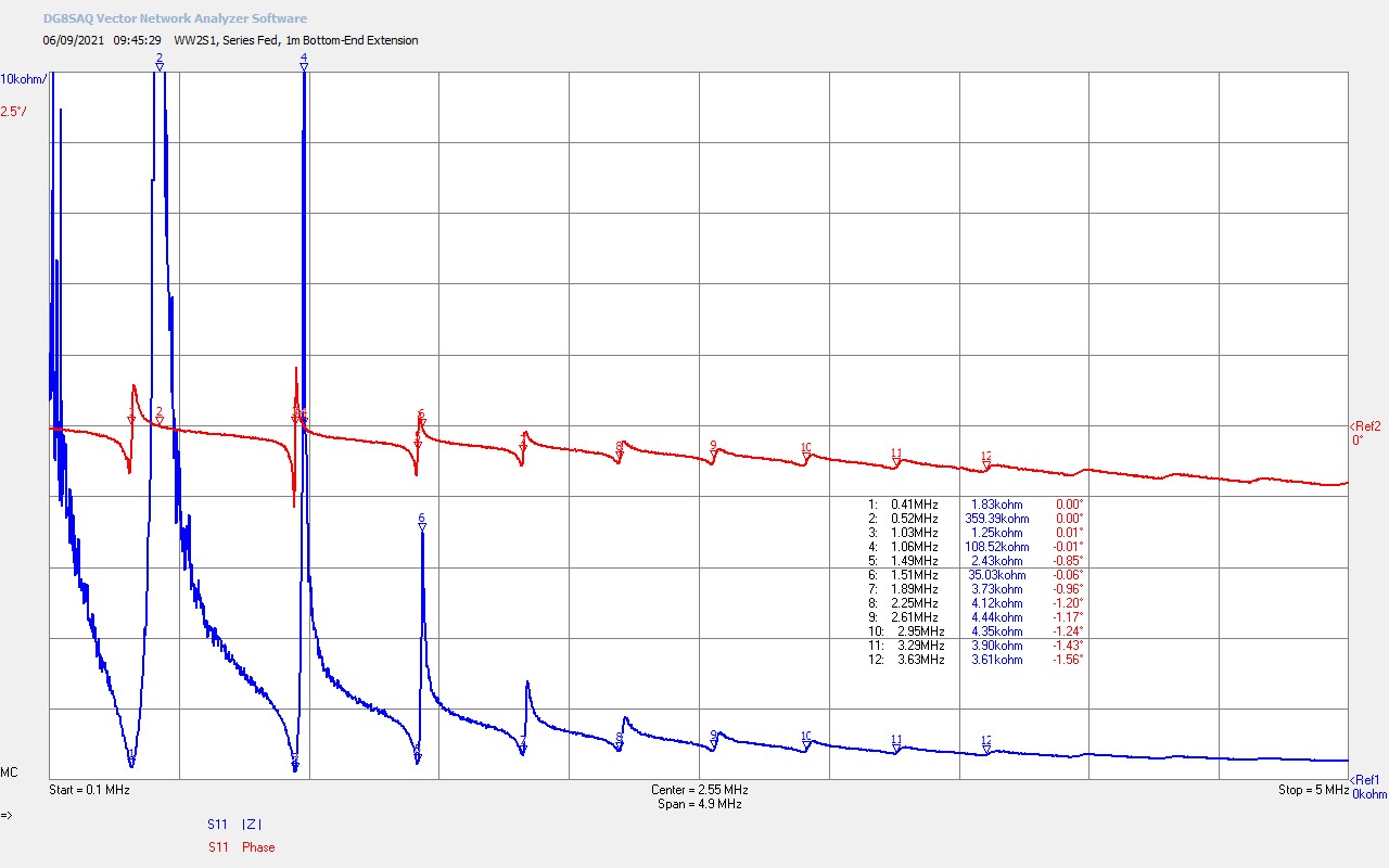
Fig 5.1. Shows the series fed input impedance Z11 for Tesla coil 1, design ƒSS = 3.49Mc. The measured fundamental series resonant mode ƒSS @ marker M1 = 3.41Mc, and with a 1m single wire extension at the bottom-end of the negative terminal of the VNWA. The parallel mode ƒSP @ M2 = 4.26Mc, and is characteristic of a standard Tesla coil design where the parallel mode is above the series mode when the secondary is on its own in a series-fed configuration. The characteristics of Tesla coil and TMT input impedance Z11 is covered in detail here Cylindrical Coil Input Impedance – TC and TMT Z11.  The large and well defined phase change at M1 shows the high quality factor Q of the coil, which mostly occurs when the geometry of the turns of the coil are not too tight, and have adequate spacing between them, in this case the distance between turns is ~ 1.35mm, the thickness of the silicone wire cladding, and the diameter of the wire is ~ 1.1mm. Geometry of Tesla coils and there design is covered in detail here Tesla Coil Geometry and Cylindrical Coil Design.

The coil is purely resistive at both the resonant modes ƒSS and ƒSP. At the series mode ƒSS reaches a minimum at ~ 70Ω, and a maximum of ~ 80kΩ at the parallel mode ƒSP. Both series and parallel modes are particularly useful depending on what type of generator is being used to excite the Tesla coil. A tuned linear amplifier, spark gap generator, or solid state inverter are best suited to driving the series mode, and a series feedback oscillator such as a class-C Armstrong oscillator is suited to drive at the parallel mode. With correct matching and tuning it is possible to couple significant power into the Tesla coil through either the series or parallel modes. The parallel mode allows for frequency adjustment dependent on how the tank circuit in the primary is setup, which is particularly useful for this experiment where a range of frequencies can be tuned dynamically during operation using a vacuum variable capacitor. If secondary feedback is arranged through a pick-up coil to the vacuum tube generator the parallel mode can be tracked dynamically with little additional tuning required during operation, other than at the band-edges where the grid-bias will need adjusting, and the feedback coil turns optimised.

At the series mode, frequency can also be adjusted by changing the wire-length at the top-end of the secondary coil. This is best affected using a telescopic aerial or other adjustable wire length, but is not so practical to adjust during operation without re-tuning the generator to the new frequency. Driven either at the series mode or the parallel mode, transmission mode conversion can be accomplished between the driving primary circuit, and the cavity of the secondary coil formed with the single-wire or transmission medium connected to the bottom-end of the secondary coil. In principle, power in the TEM transmission mode in the primary circuit, can be transferred and transformed to the LMD transmission mode in the cavity of the secondary coil. The cavity in principle can be made to extend over very large distances, presenting the possibility for power transfer at very low-loss over very large distances in the far-field, and many times the wavelength of excitation at the generator. A second tuned Tesla coil in the cavity of a TMT system transforms the LMD mode back to the TEM mode in the receiver primary. The transfer of power, which accompanies the transformation of transmission mode from the cavity in the secondary to the primary circuit of the receiver, can then be used to do work in the load. It is interesting to note that the frequency of the LMD mode in the cavity is not the same as the frequency of the TEM modes in the primary of the transmitter and receiver.

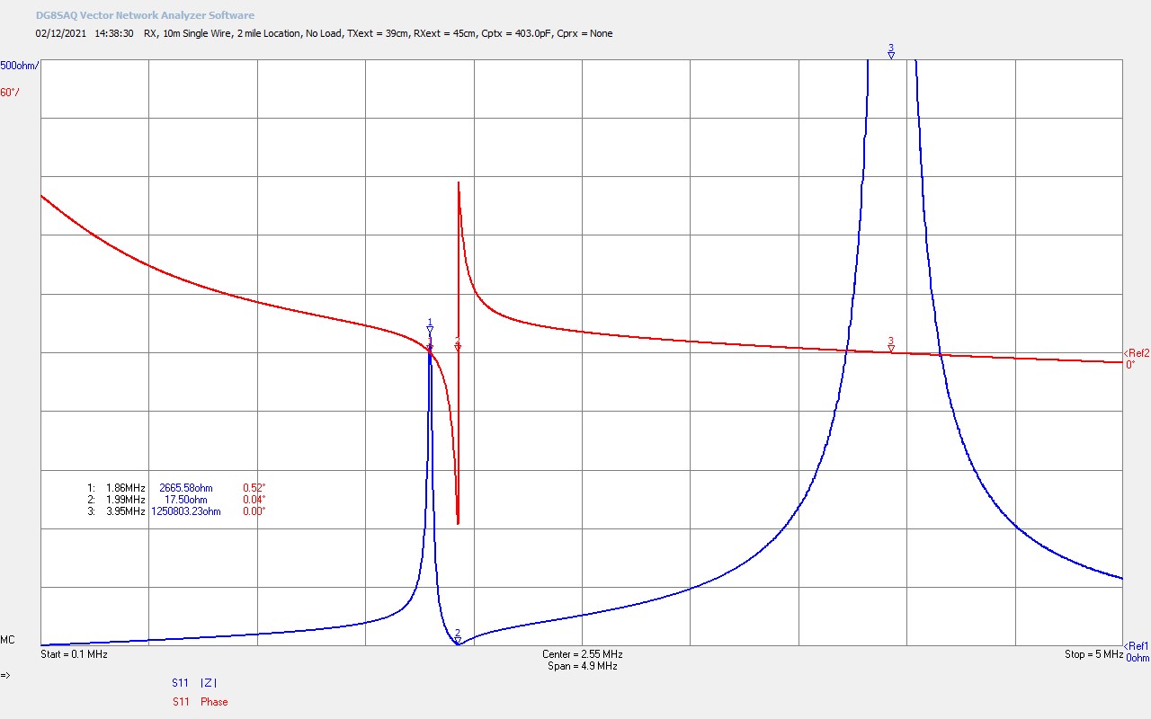
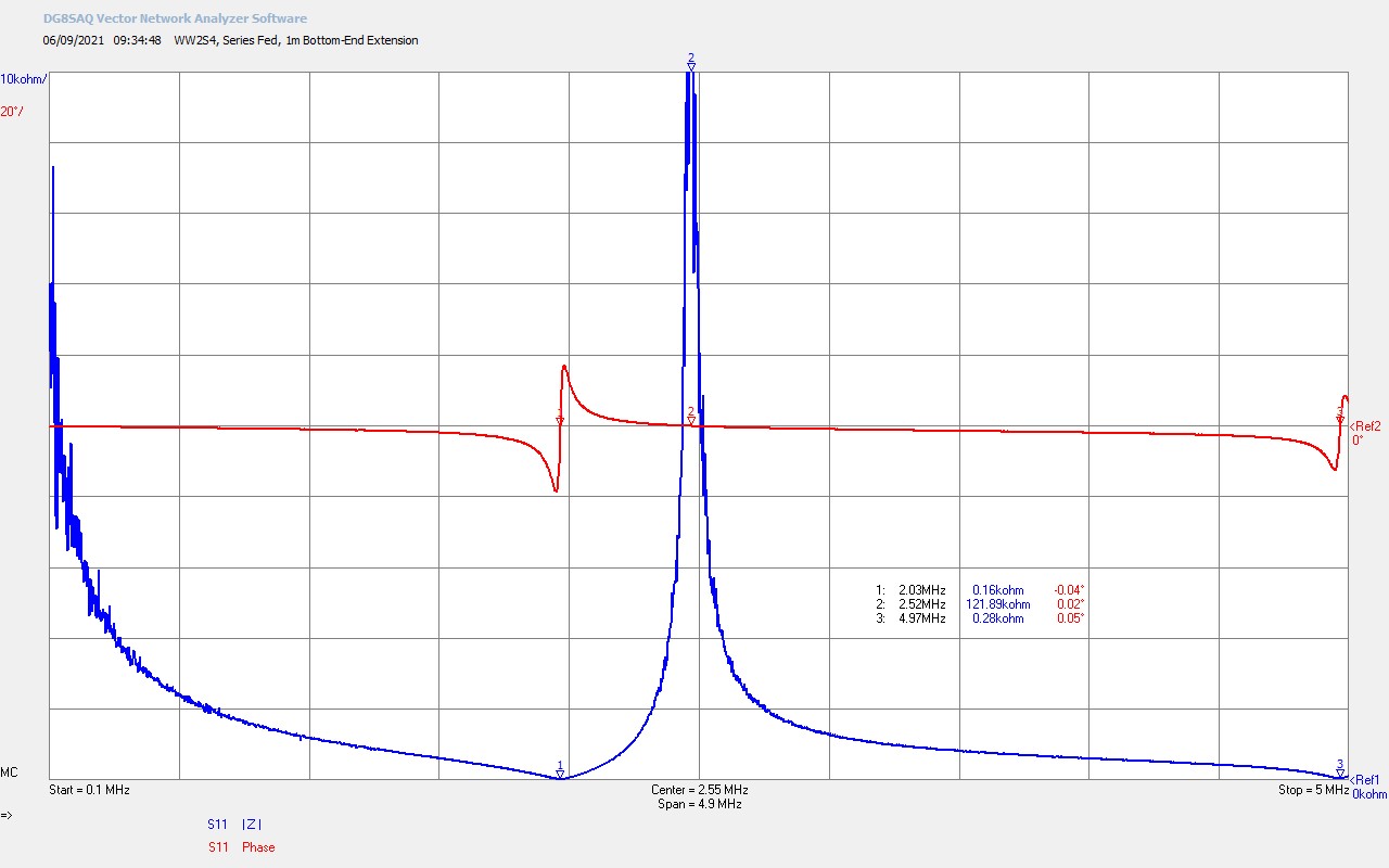
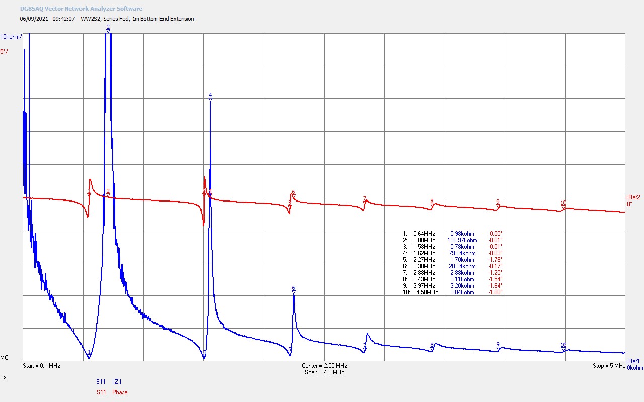
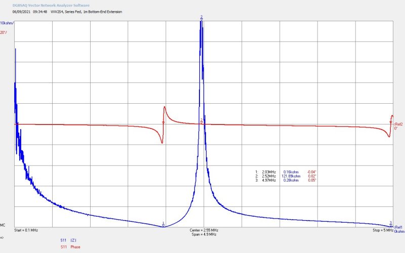
Fig 5.2. Here secondary coil 2 has series mode ƒSS = 2.03Mc, and parallel mode ƒSP = 2.52Mc. Compared to coil 1 this is more tightly wound, with reduced conductor spacing and more turns, and hence the Q has reduced significantly, as can be seen in the reduction of the magnitude of the phase swing at M1. Both coils 1 and 2 are on the same magnitude and phase scales, and the phase reduction for this coil is a factor of ~ 2. The longer wire length has also considerably increased the coil resistance at the series and parallel modes, RSS = 160Ω, and RSP = 122kΩ. The second odd harmonic at 3λ/4 is just visible at M3 @ 4.97Mc. This coil when combined with the primary in the video experiment shows the transition between the upper parallel mode and the fractal “fern” discharge, and the lower parallel mode which shows the “swords” discharge with an additional slight curvature. However, in the series-fed Z11 small signal impedance analysis there is nothing obvious that suggests some different electrical characteristic or feature that may be responsible for this dramatic transition from one discharge form to the other. It is worth considering at this point as to whether interaction between harmonics has any bearing on the discharge form. As the fundamental resonant frequency goes down through designed wire-length the harmonic frequencies become progressively closer which makes it more possible for energy to be transferred between the harmonics through the non-linear nature of the discharge.

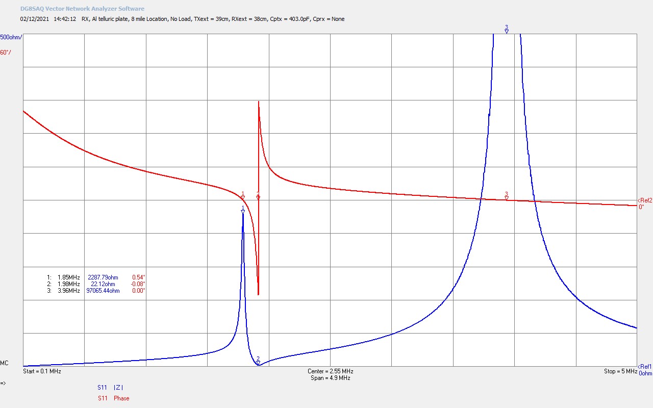
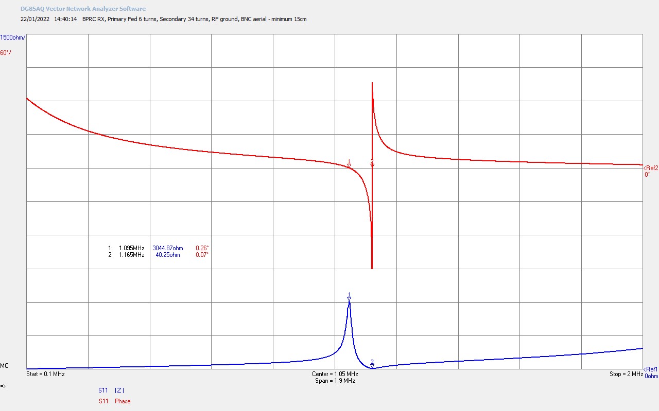
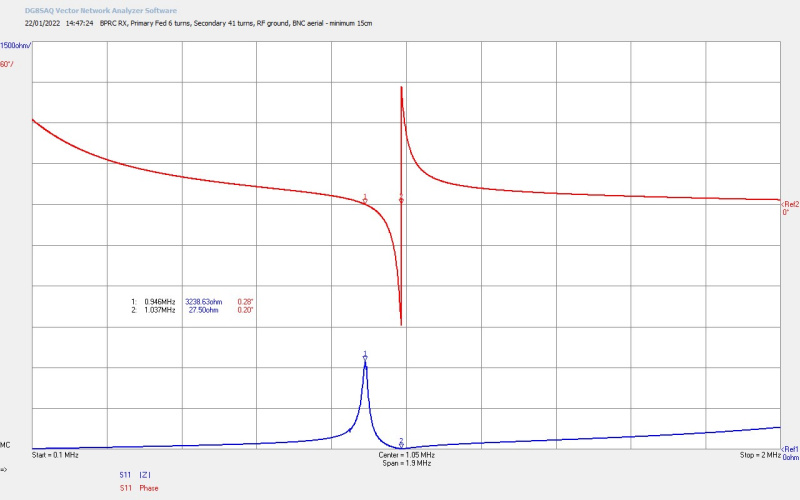
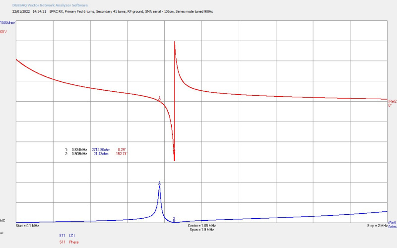
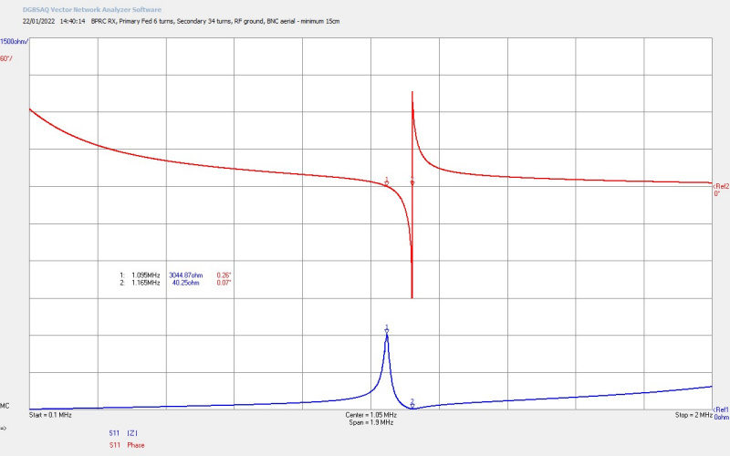
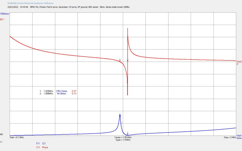
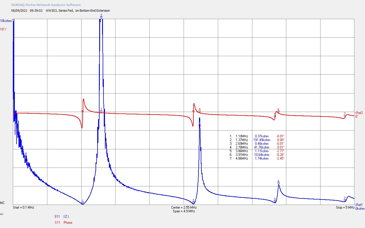
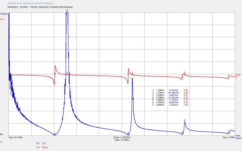
Fig 5.3. Shows secondary coil 3 and the final coil used in the video experiment. Here the 2nd, 3rd, and 4th odd harmonics are very clearly defined. The phase scale has been expanded from 20°/div to 10°/div to show clearly the phase swing as it collapses with reducing Q of the coil, much reduced wire spacing, increased turns, and hence increased series coil resistance. Operation of this coil was still at the fundamental resonant modes rather than at harmonics, and when combined with the primary, (shown in figures 6), result in the parallel mode operating points used in the video. The series mode ƒSS = 1.10Mc with RSS ~ 370Ω @ M1, and the parallel mode ƒSP = 1.37Mc with RSS ~ 191kΩ @ M2. Harmonic frequencies extend at nλ/4 where n is an odd number, and with progressively reducing Q, and hence have a smaller and smaller impact as frequency increases. This coil clearly displayed the straight “swords” discharge at both the upper and lower parallel modes of operation, the slight curve was no-longer present and each discharge streamer projected straight outwards from the breakout point at the top-end of the coil. Streamers continued to be white and “hot” consistent with the generator drive which is at a maximum capped voltage defined by the two series transformers driven by the SCR, and current rich controlled by the “on” phase of the SCR power control.

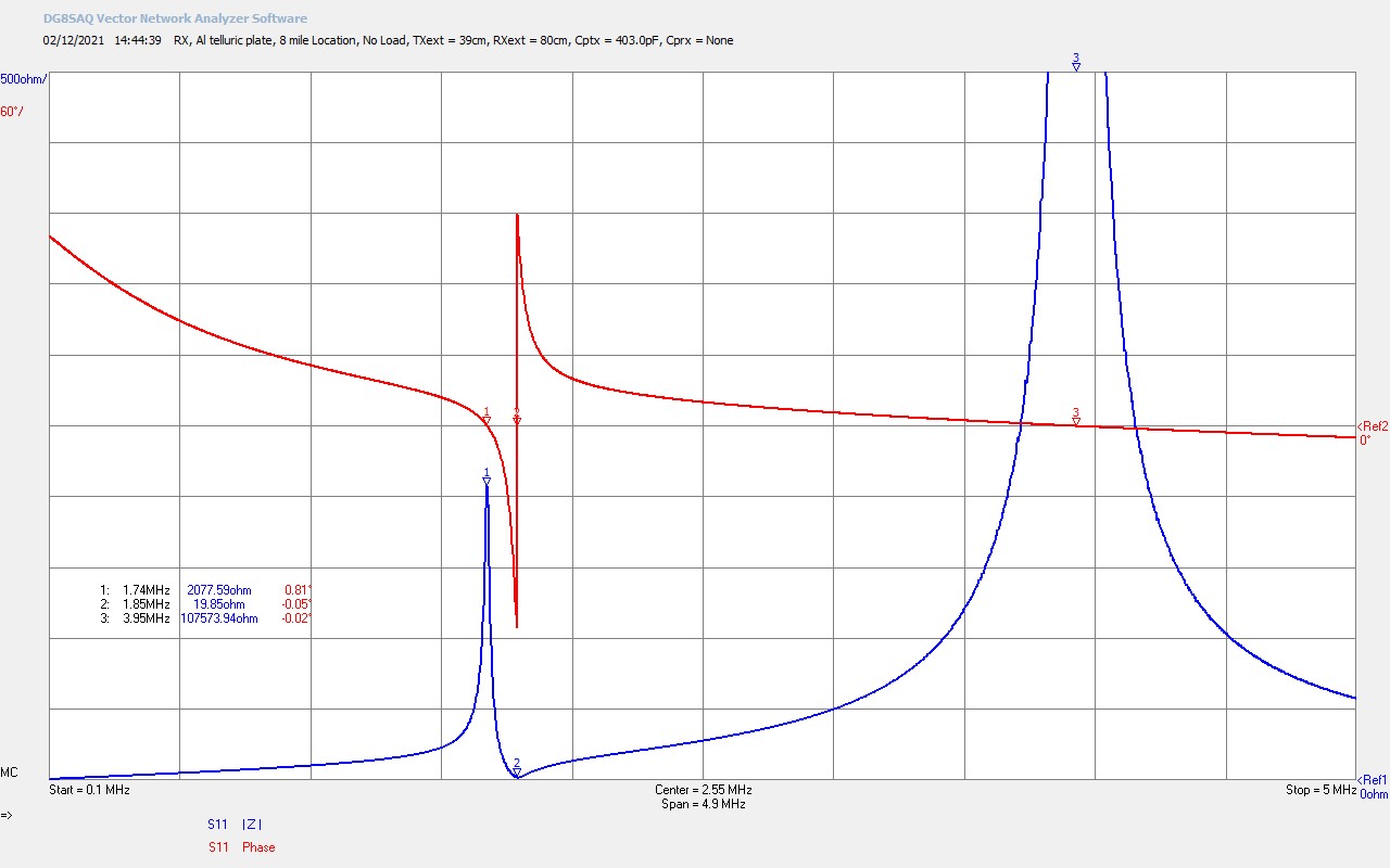
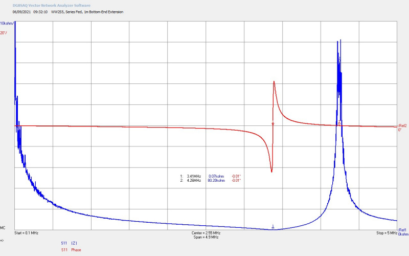
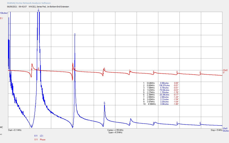
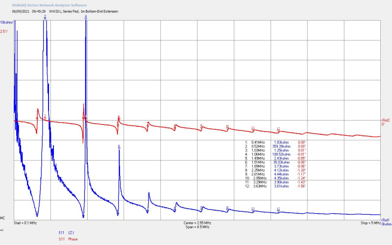
Fig 5.4. and 5.5. Show the two lower frequency coils 4 and 5 that  were not demonstrated in the video experiment. In both Z11 measurements there are a very large number of harmonics, and the phase scale has been expanded again from 10°/div to 5°/div to reflect the collapsing Q of the coils, the rapidly rising series resistance from thinner gauge wire of many turns, and hence much longer wire lengths. Lower frequency Tesla coils like these tend to oscillate at a harmonic frequency when driven by a feedback oscillator using the parallel mode resonant frequency. In Fig. 5.4 it can be seen that the Q of the second odd harmonic at M3 is actually higher than the fundamental at M1. In this case the coil is more likely to stably oscillate at ƒSP2 the second harmonic parallel mode when driven using a series feedback oscillator. This will become clearer when we look at the parallel mode points when combined with the primary in figures 6.

Consequently many lower-frequency standard Tesla coils presented on the Internet tend to oscillate stably at the 2nd or 3rd harmonic when driven by a series feedback oscillator. To drive these two coils at their series fundamental resonant modes a fixed frequency linear oscillator or amplifier needs to be used where the frequency can be selected and fixed, and the generator is specifically matched at this fixed frequency, and then considerable power can be stably transferred to the secondary. This generator is more complicated than the series feedback tube oscillator, and required more setup, tuning, and matching to run at the equivalent power used in this experiment. For compatibility and simplicity with the previous Wheelwork of Nature experiment, I have kept the generator the same as before and avoided any additional complexity in the experiment, and its possible interpretation. I will look to make a video of these two low frequency coils driven by this form of fixed frequency generator in a subsequent experiment.

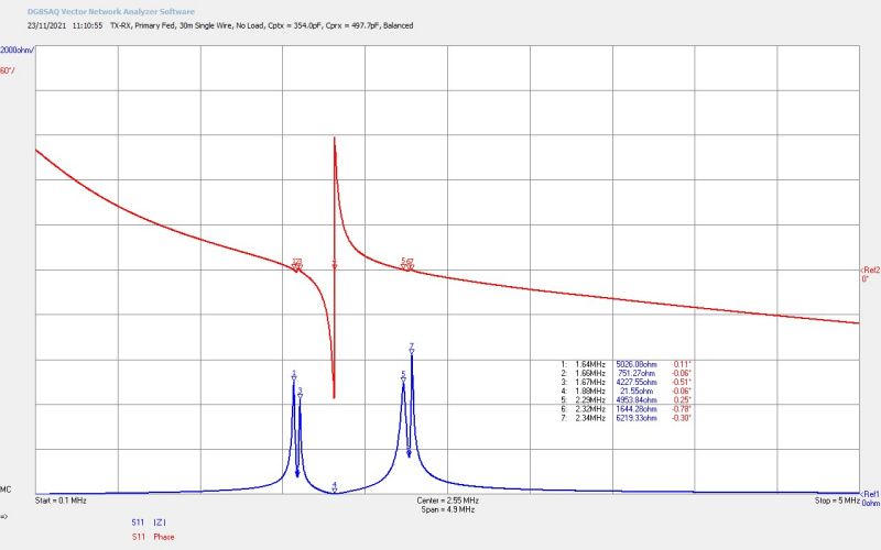
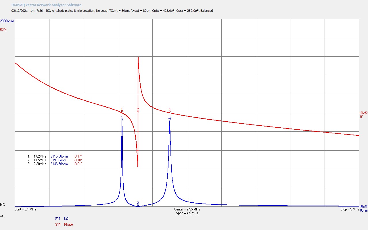
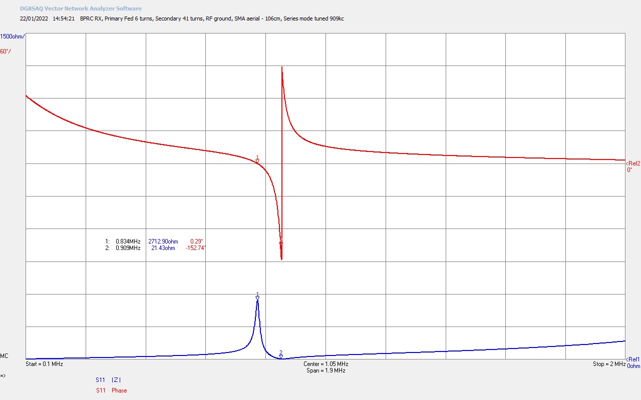
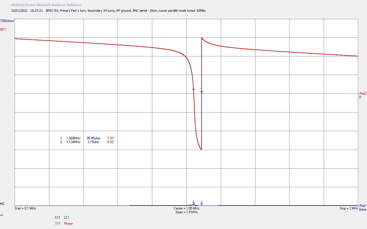
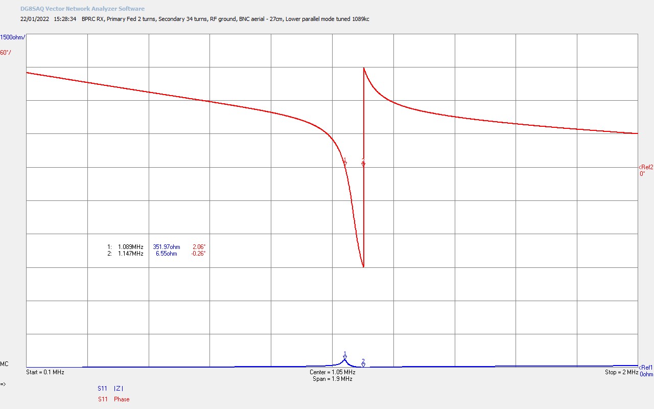
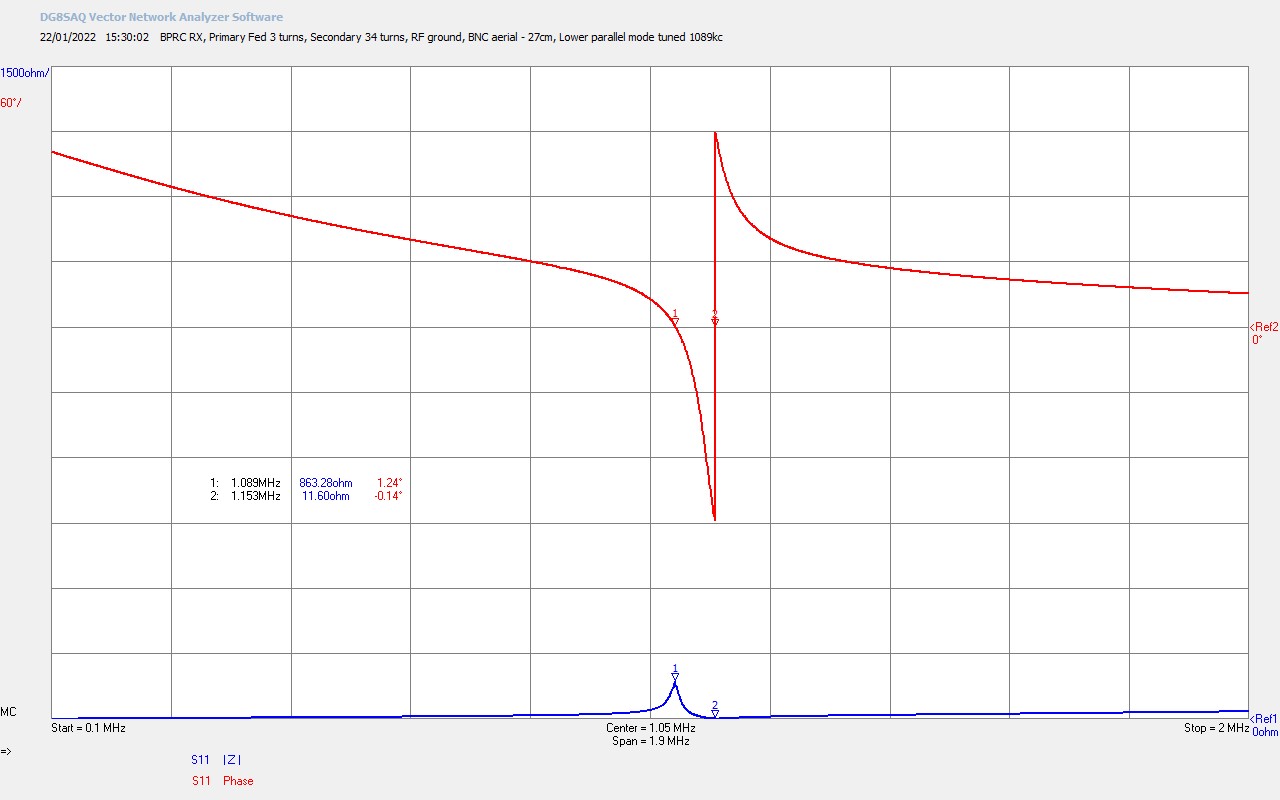
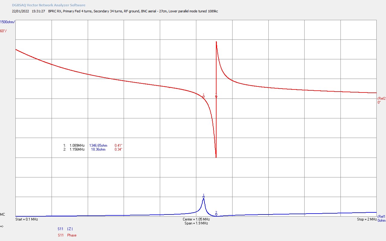
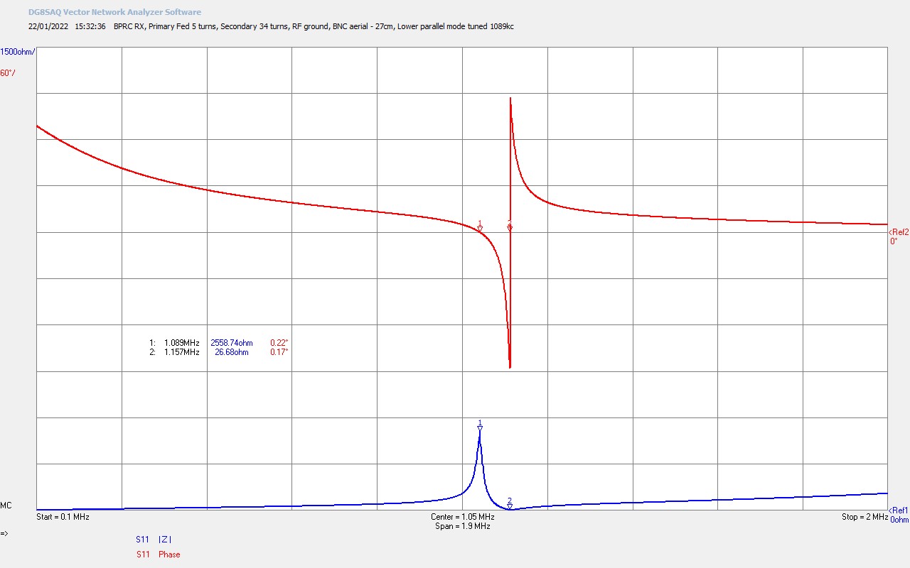
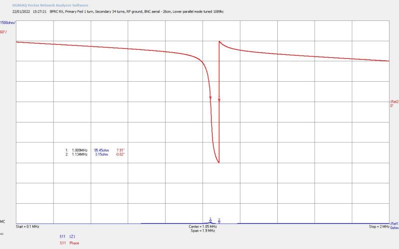
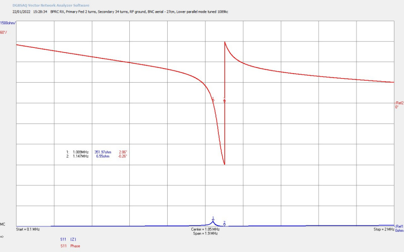
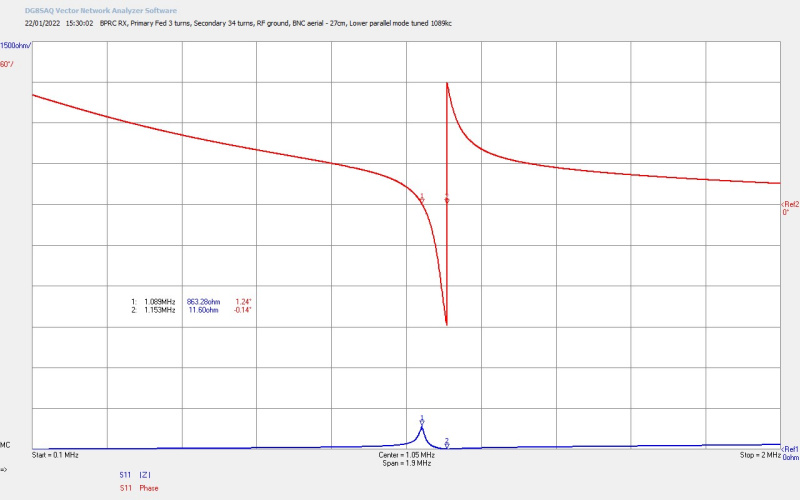
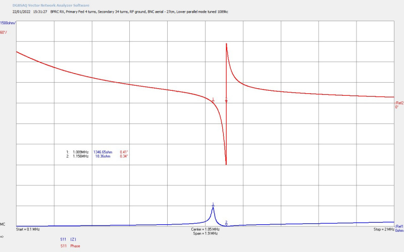
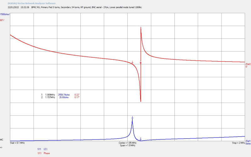
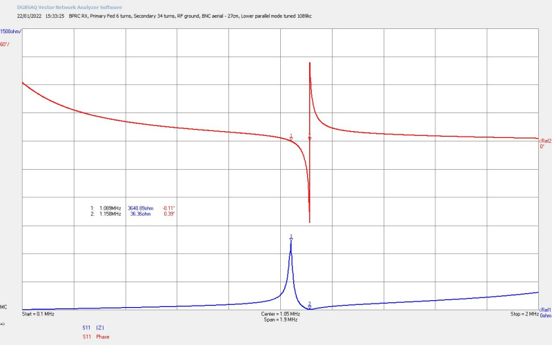
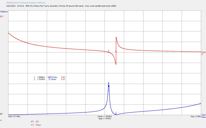
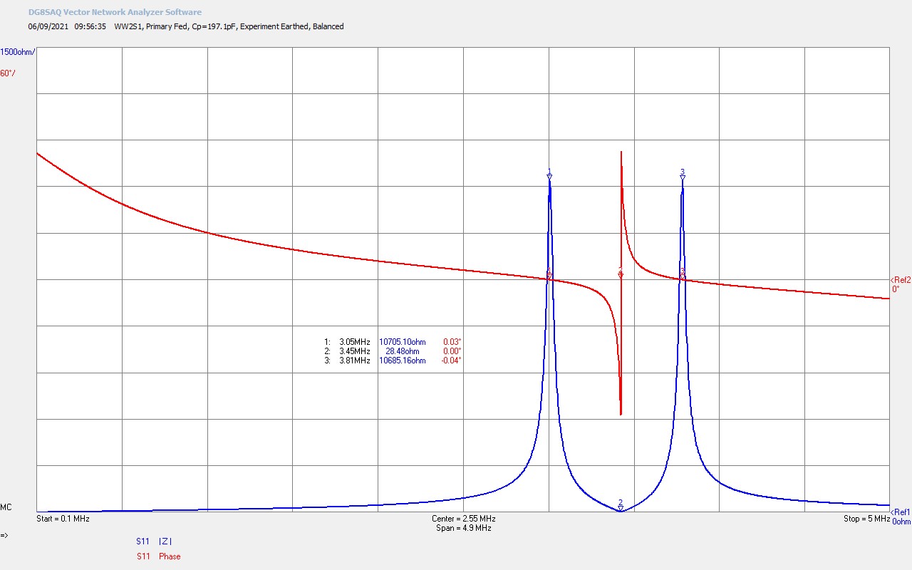
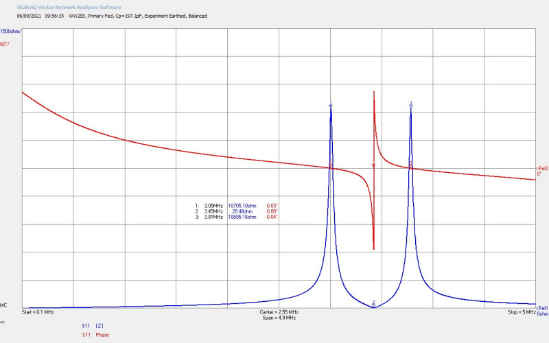
Figures 6 show the balanced parallel modes for each secondary coil when combined with the primary and tuned to balance using the primary circuit tank capacitor Cp. The primary tank capacitor is based on a KP1-4 10kV vacuum variable capacitor with range 20-1000pF. For the lower frequency secondary coils 3, 4, and 5, it was necessary to add a parallel static capacitor to the variable capacitor in order to increase the tank capacitive loading, and hence achieve balance of the upper and lower parallel modes.

To view the large images in a new window whilst reading the explanations click on the figure numbers below.

Fig 6.1. Here secondary coil 1 has been added to the primary circuit shown in Fig. 1.5. The primary tank circuit is formed by the primary coil, the vacuum variable capacitor, and any additional fixed loading capacitance. When tuned correctly the parallel mode from the secondary coil occurs at the same frequency as the parallel mode from the primary coil. When the coils are coupled energy is exchanged backwards and forwards between the two parallel modes which causes “beat” frequencies, and a frequency splitting of the two parallel modes. The degree of splitting depends primarily on the magnetic coupling coefficient k, the Q of the two coils, and the geometry of the coils. The parallel mode from the primary results from the self-resonance of the primary coil, which is typically for the coil shown, around 30-50Mc for the fundamental series mode. The parallel mode of this self-resonance is at a much lower frequency than the series mode, and can be tuned down to even lower frequencies by addition of CP, the primary circuit tuning capacitance. The splitting of the two parallel modes from the primary and secondary results in the lower and upper parallel resonant modes of the Tesla coil, and can be driven and tuned directly when using a series feedback oscillator type generator. Tesla coil resonance modes are covered in much more detail here Cylindrical Coil Input Impedance – TC and TMT Z11.

When the parallel modes are tuned using CP to a point where the magnitude of their impedance is equal, and the phase angle of their impedance is zero, then the balanced mode is achieved. This condition balances the two parallel modes of the Tesla coil either side of the series fundamental mode, and has been found in some cases to be an optimum driving condition for a Tesla coil for certain different types of phenomena including, High Efficiency Transference of Electric Power in the close mid-field region, balanced TMT setup for LMD transmission experiments in Transference of Electric Power, and the equilibrium initial condition for experiments in the Displacement of Electric Power. This typical balanced mode for a Tesla coil is shown in this figure, where the fundamental series resonant mode is at M2 @ 3.45Mc, and the lower and upper parallel modes are at M1 @ 3.05Mc, and M3 @ 3.81Mc, and the primary tank capacitance Cwas set at 197pF to achieve this balanced point. At all of these three resonant modes the phase of the impedance is 0 degrees, showing the input impedance seen by the generator is entirely resistive, with no reactive components. The Tesla coil can be driven from any one of these three modes, and considerable power coupled intro the resonator from the generator.

Generator matching at any of these three modes requires an impedance transformation from the output impedance of the generator to the input of the Tesla coil, where at the three resonant modes this can be accomplished through a transformation of the resistive component only. For the series mode this usually involves using a tuning stage such as an high-power antenna tuner, specifically arranged balun or unun, or a fixed or variable RF transformer such as a “swing-link” tuning transformer. For example, to tune the series mode directly at M2, the input impedance Z11 is entirely resistive and RS = 28.5Ω. If a linear amplifier is being used as the generator with a usual output impedance of 50Ω, then an antenna tuner could be used to produce a good match with standing wave ratio (SWR) ~ 1. A 1:2 Balun (not 2:1) could also be used here since the ratio of the input resistance at M2 is close to 1:2. A balun is also useful here to convert the unbalanced coaxial feed of the generator to the balanced half-wave primary coil feed (λ/2). This considerably reduces radiated energy from the outer surface of the coax cable between the generator and Tesla coil, and also improves measurement accuracy when using inline RF power meters such as Bird Thruline analog 4410A, and digital 4391A.

For the parallel modes the input impedance is a much higher resistance e.g. at M1 = 3.05Mc, Rs ~ 10.7kΩ. This high impedance is very suitable for driving directly using the high plate impedance of a vacuum tube oscillator. When arranged properly at resonance so the match is purely resistive, or as close as can be accomplished, the match can be coarse adjusted through the number of feedback turns from a pickup coil placed close to the secondary coil. This type of positive feedback to the oscillator also means that the parallel mode frequency can be tracked by the oscillator, and hence a simple but highly effective tracking generator is arranged. By adjusting the position of the parallel modes, and which parallel mode is dominant, and hence the point of tracking, the generator can be auto-tuned over a wide frequency range either side of the series fundamental mode. Fine tuning of the match at any specific frequency is accomplished by adjusting the grid bias and/or the grid leakage at the grid storage circuit. If both of these are arranged with a rheostat very fine tuning and matching can be accomplished over a wide range of tracked frequencies. This particular generator arrangement has been very successfully used so far in the Wheelwork of Nature and Transference of Electric Power experimental series. It is relatively simple to arrange, is very tolerant to moderate mismatch conditions between the generator and the Tesla coil, and is highly flexible in its variable frequency range which can be adjusted directly during operation by adjustment of a vacuum variable capacitor.

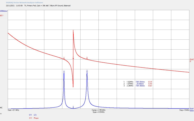
When operated in the parallel mode using a feedback oscillator the tank capacitance CP was tuned either side of the 197pF necessary for the balanced point. At the balance point the oscillator output will not be stable as it jumps between the equal magnitude lower and upper parallel modes, and back again. For stable operation in the lower parallel mode CP is increased, and in the video experiment CP ~ 230pF was used to set the starting point of oscillation at 2.7Mc with the lower parallel mode impedance dominant. For stable operation in the upper parallel modes CP is reduced, and in the video experiment CP ~ 150pF was used to set the starting point of the oscillation at 3.2Mc with the upper parallel mode impedance dominant. The measurements taken in figures 6 are with the secondary coil connected to the experiment earth, that is, with the line earth of the apparatus only. When the experiment was further connected down to the RF earth for operation, the effective wire length increases slightly, and hence the fundamental series mode shifts down from ƒO = 3.45Mc to ƒO ~ 3.0Mc, the lower parallel mode ƒL ~ 2.8Mc, and the upper parallel mode ƒU ~ 3.1Mc which correspond with the operating frequencies presented during in the video experiment.

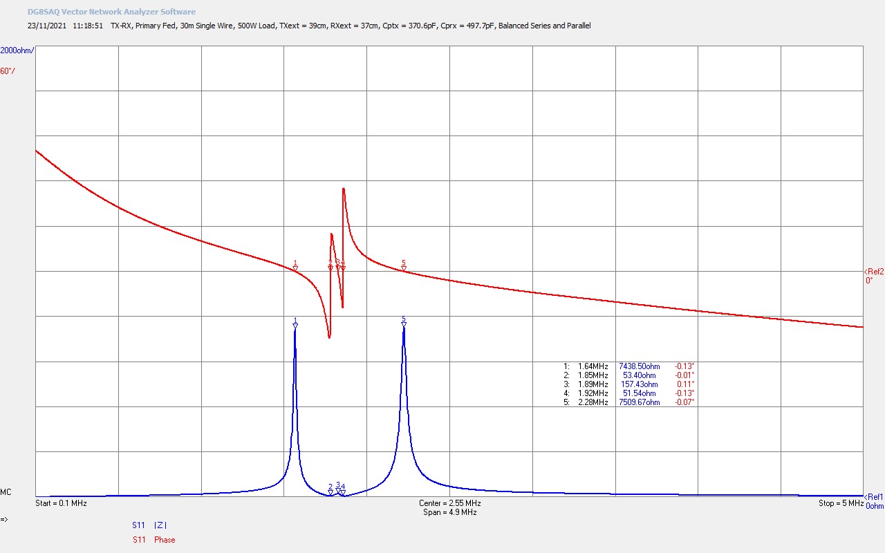
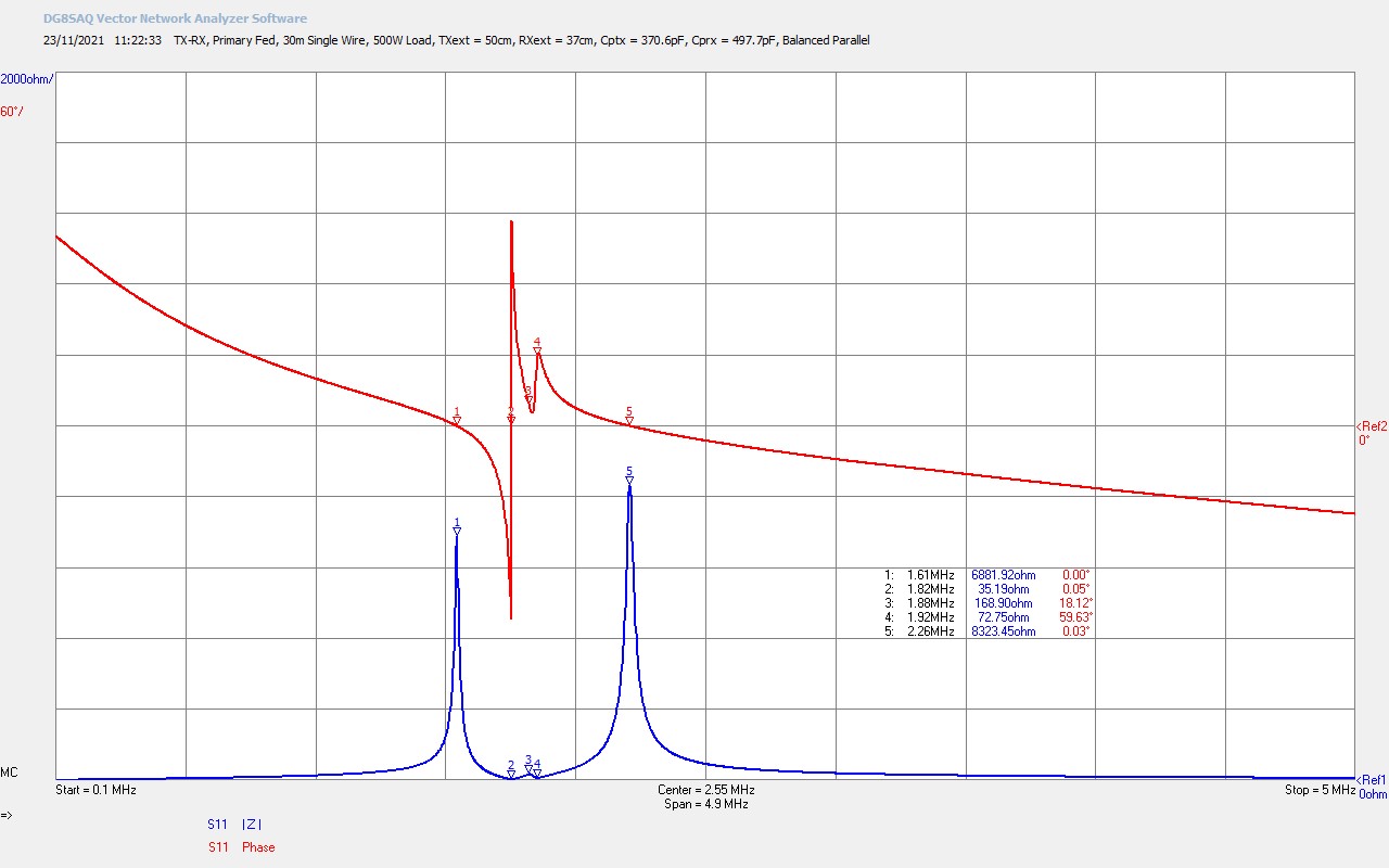
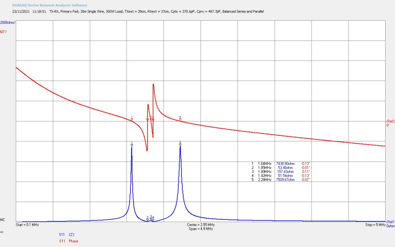
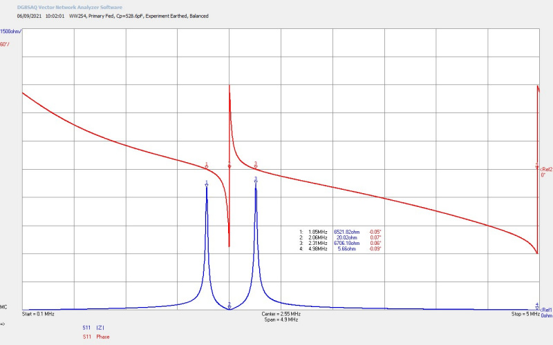
Fig 6.2. Here Tesla coil 2 has been balanced in the same way by increasing the primary tank capacitance to CP ~ 529pF, ƒO @ M2 = 2.06Mc, ƒL @ M1 = 1.85Mc, and ƒU @ M3 = 2.31Mc. The resistance of the two parallel modes have decreased significantly, mainly due to the additional capacitive loading in the primary, and also slightly from the lower frequency. The series mode resistance has also dropped from 28.5Ω @ 3.45Mc to 20.0Ω @ 2.06Mc. In this scan the series fundamental mode of the primary coil can just be seen at the very top-end of the scan at M4 = 4.98Mc. This also shows the wide frequency gap between the series mode of the primary coil self-resonance and the parallel mode, which is here balanced with the parallel mode of the secondary coil. As the primary tank capacitance is increased this series mode self-resonance of the primary coil moves lower in frequency, and can start to overlap with harmonic frequencies from the secondary coil. In this case a complex resonance is setup, and energy from the generator distributes over a number of different frequencies, producing a non-sinusoidal generator oscillation, and reduced power in the intended driven mode of the Tesla coil, (one of the three fundamental modes series and parallel). This distribution of energy across harmonic modes can produce unusual phenomena in the characteristics of the Tesla coil, and will be covered in more detail in a subsequent experiment.

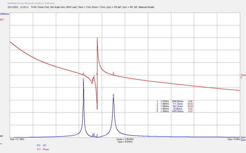
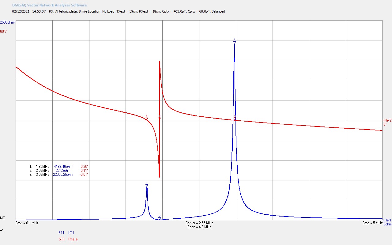
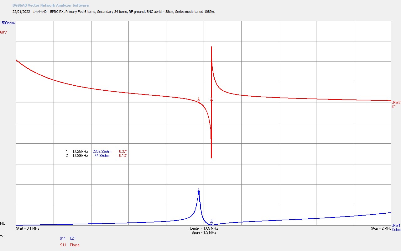
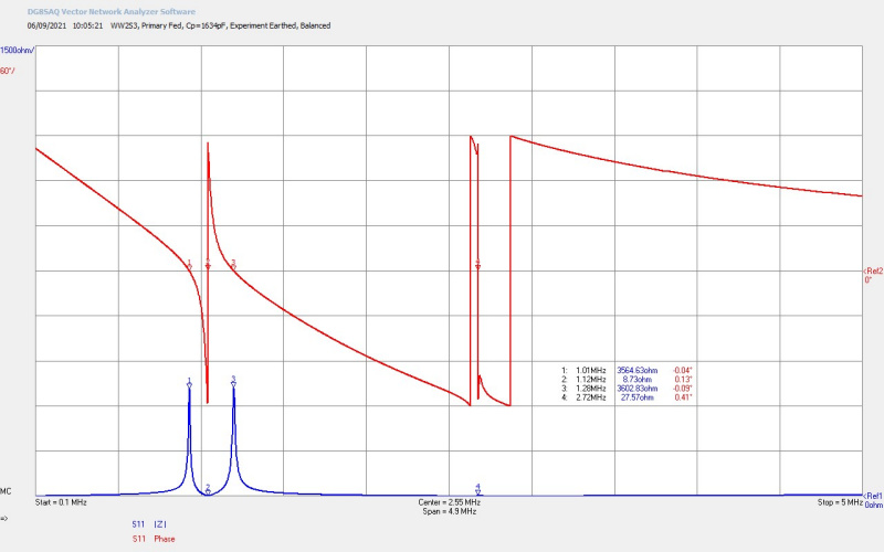
Fig 6.3. Shows directly an example discussed previously where the self-resonance of the primary, tuned down in frequency to the balance point using increased CP, has overlapped and hence interacted with the second odd harmonic of Tesla coil 3. From Fig. 5.3. we can see that the second odd harmonic has a fundamental frequency ƒSS2 @ M3 = 2.69Mc. The two interacting resonant modes from the primary and the secondary take place centred around M4 @ 2.72Mc, where a number of phase changes can be seen as two series fundamental modes move past each other. As these modes are coupled between the two coils through the magnetic coupling coefficient k2, they interact and again cause “beat” frequencies and a splitting of the two series modes for the duration of their overlap interaction. In this condition when the Tesla coil is pumped by the generator at any of the fundamental series and parallel modes, M1 – M3, some of the coupled power will also interact at the second harmonic mode overlapping with the primary fundamental mode. A complex resonance condition is setup, and the generator drive oscillation will become a complex waveform with multiple interacting frequencies. Less power will be coupled through the fundamental modes, as some will be lost to the “beating” second harmonic mode.

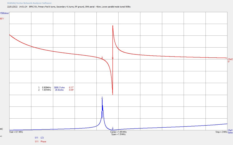
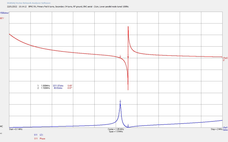
The loading primary capacitance in this case necessary to balance the parallel modes CP = 1634pF, was made by adding 1000pF fixed capacitor in parallel with the KP1-4 vacuum variable capacitor set at ~ 634pF. In balanced arrangement ƒO @ M2 = 1.12Mc, ƒL @ M1 = 1.01Mc, and ƒU @ M3 = 1.28Mc. It should also be noted that the increased capacitive loading of the primary is now reducing the Q significantly of the Tesla coil. In this case the coil can still be driven at the parallel modes by a feedback oscillator as shown in the video experiment, but the operation band is narrower, and performance diminishes more quickly as you tune away from the fundamental series mode at 1.12Mc.

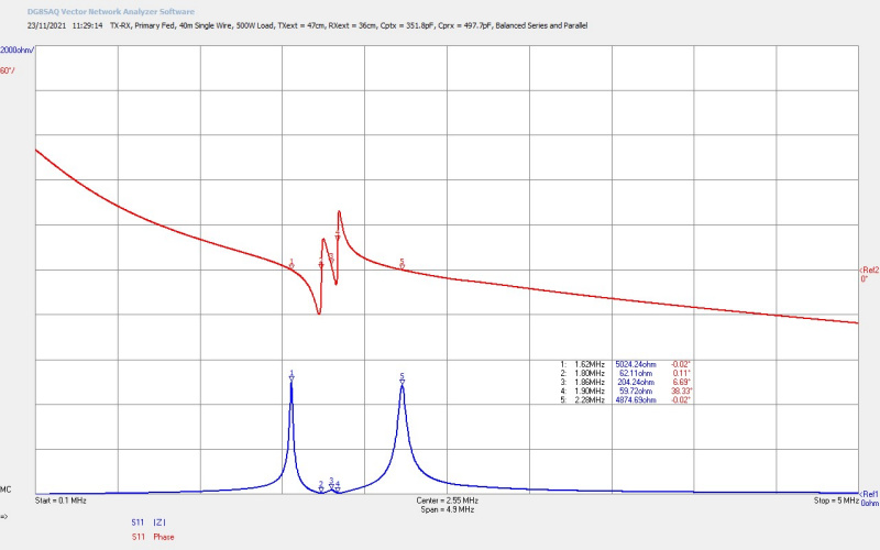
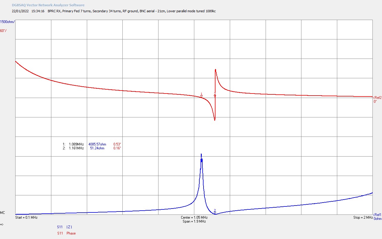
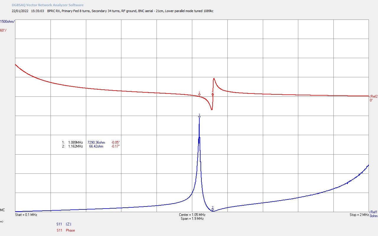
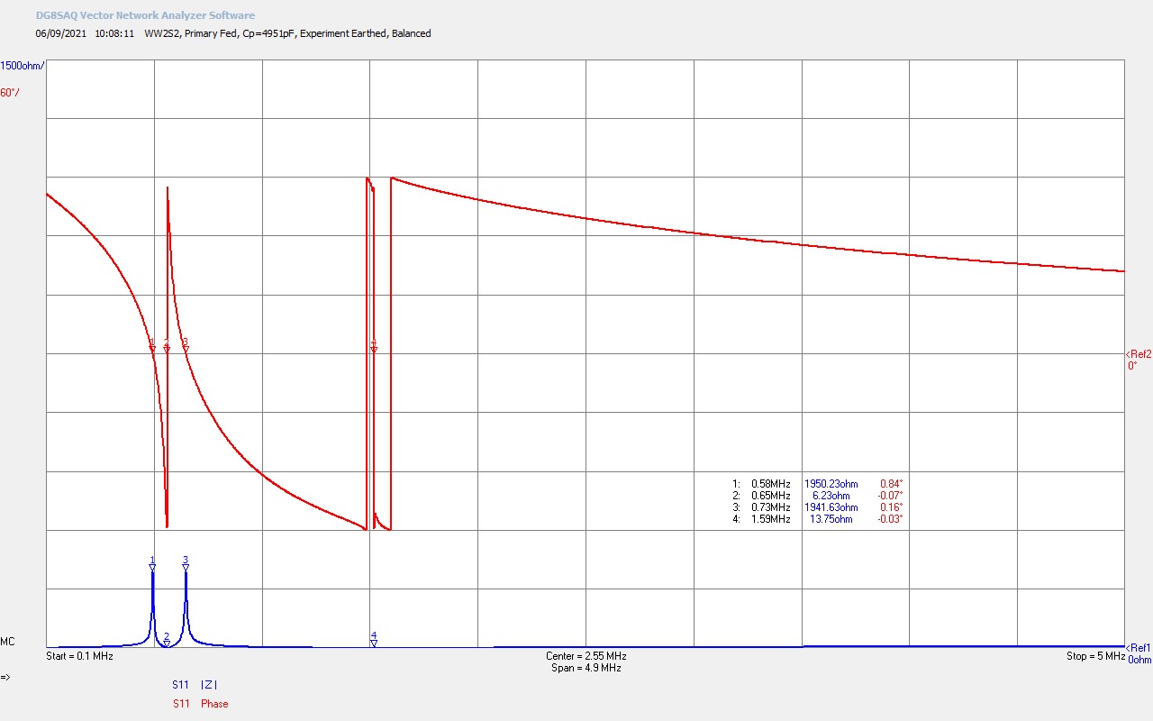
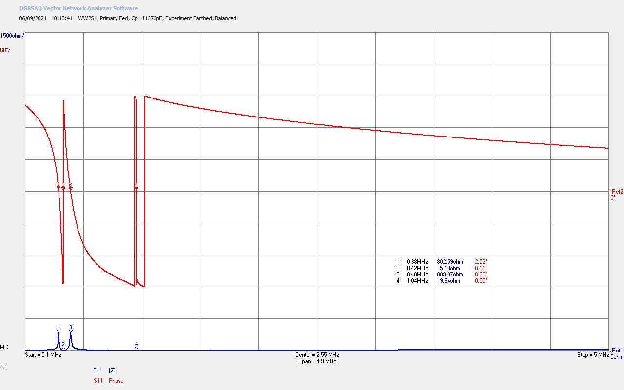
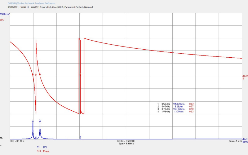
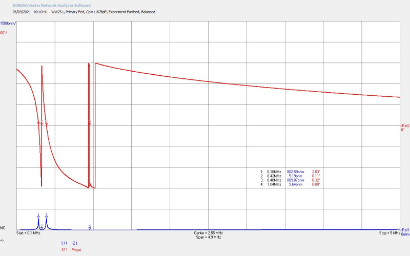
Fig 6.4. and 6.5. for the lower frequency Tesla coils 3 and 4 show exactly the same characteristics and trends as for coil 3. Here the Q can be seen to be diminishing rapidly and for these two coils is it is exceedingly difficult to get them to oscillate at their fundamental modes when loaded so heavily with primary capacitance. For coil 4 Cp ~ 4951pF for balance, and for coil 5 CP ~ 11676pF. Coil 4 and 5 could only just be driven at their upper parallel mode around 600kc and 890kc respectively using the generator as setup for this experiment, although the discharge output was very small for large amount of power provided by the generator, (up to 3kW in testing for a discharge of no more than several centimetres). The discharge form in both cases was straight “swords” in higher density than the higher frequency coils.

If the capacitive loading was reduced in the primary to move oscillation away from the fundamental modes only, then both coils 4 and 5 would adequately oscillate around ~ 1.0-1.5 Mc, where the Q of the Tesla coil was higher, and there was adequate feedback from the secondary coil to the generator. From Figs. 5.4 and 5.5 this corresponds to the 2nd harmonic for coil 4, and the 3rd harmonic for coil 5. For fundamental operation of these two coils at maximum power and performance, a fixed frequency linear amplifier or oscillator should be used, tuned and matched to the fundamental series resonant frequencies ƒO @ M2 ~ 650kc for coil 4, and ƒO @ M2 ~ 420kc for coil 5. I will look to demonstrate the characteristics of these two coils using the different generator in a subsequent video, which will show and confirm that the discharge form for both of these generators is also straight “swords”.

Fractal “Fern” vs Straight “Sword” Discharges

Figures 7 and 8 show a selection of discharge images taken from the video experiment, and in order to illustrate the differences between the fractal “fern” shown in figures 7, and the “swords” discharge shown in figures 8. The images are selected from a number of different operating points and coils and comparable operating power. For a detailed consideration of the fractal “fern” discharge see the discussion in The Wheelwork of Nature – Fractal “Fern” Discharges.

It can be clearly seen from both these figures that the general characteristics of the main streamers appear almost identical for “ferns” and “swords”. The structural detail along the length of the streamers has in common a “hedge” of corona, micro-filaments and strands emanating orthogonally along its length, and distinct places where sub-tendrils emerge. In the “swords” discharges there are very few emerging sub-tendrils from the primary, although there is evidence that sub-tendrils are starting to emerge they do not progress very far. In the “fern” discharge there are well defined secondary and even tertiary tendrils that branch at specific points from the main streamer. This is distinctly different for the “swords” where the main streamers all appear to extend straight outwards from the breakout point, with no major secondary or tertiary tendrils.

Of course the most distinct difference between the “ferns” and the “swords” is the change in curvature of all streamers and tendrils. The “fern” takes on the appearance of the beginning of a spiral extending through an invisible trajectory to an invisible inner focus point. It has been shown in the previous post of this series that the spiral may have golden-ratio proportions, and it has been conjectured that the focus of the spiral could be a source or sink point for the discharge. In contrast the “sword” discharge extends straight out from the breakout point without curvature at the outer end for the lowest frequency discharges from coil 3, and as far as 30cm long when operated around 2kW of generator input power, and in the centre of the parallel mode band. In the transition between “ferns” and “swords” in coil 2 some curvature can still be observed as the “fern” straightens out to a “sword”, which can be seen in more detail in the next figures.

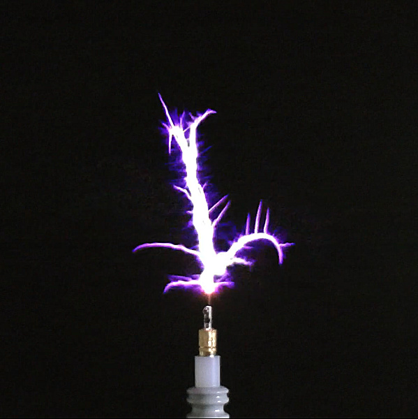
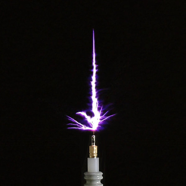
Figures 9 below show a set of discharge images of the sequence of the change of discharge form from coil 1 upper parallel mode, through the intermediate modes, and to coil 3 lower parallel mode in order of descending frequency. Each image has been selected from the video experiment as a general representation of the form of the discharge at the centre of the respective mode, and where possible with comparable generator input power.

To view the images in a new window whilst reading the explanations click on the figure numbers below.

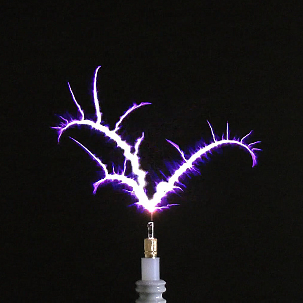
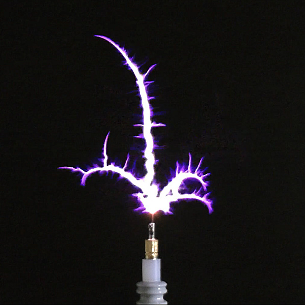
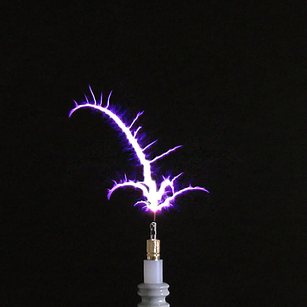
Fig 9.1. The fractal “fern” from the upper parallel mode of coil 1 at 2.97Mc  and 1.6kW shows the tightest and most dense form of the “fern” discharge. There are many primary streamers, some with secondary tendrils. The spiral curve at the tendril-ends is well developed, and many smaller orthogonal tendrils are present. Here a primary streamer in the centre is in the process of extinguishing which starts at the breakout point and travels outwards along the tendril as the energy of the tendril is exhausted to its outer limit. It is this observation in the previous post in the series that gave rise to conjecture that the focus point of the invisible spiral may act as sink for the streamer. Typically this highest frequency “fern” in the sequence is characterised by many well formed fractal tendrils that are more densely packed together, and the overall discharge form takes on the appearance of a “ball” with a fractal tree inside.

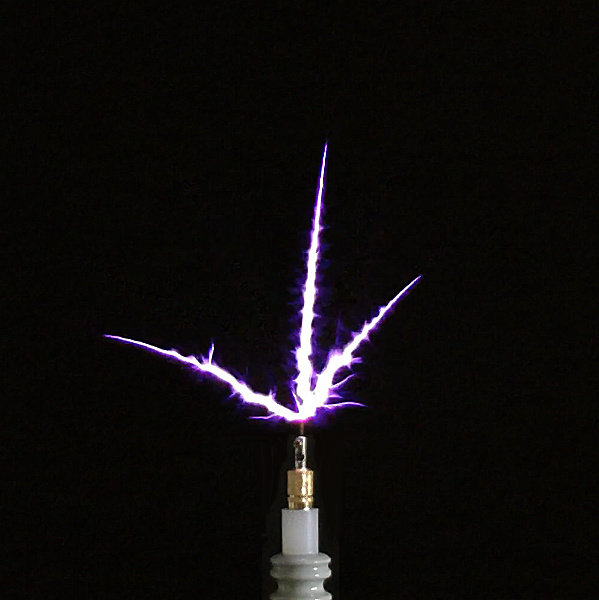
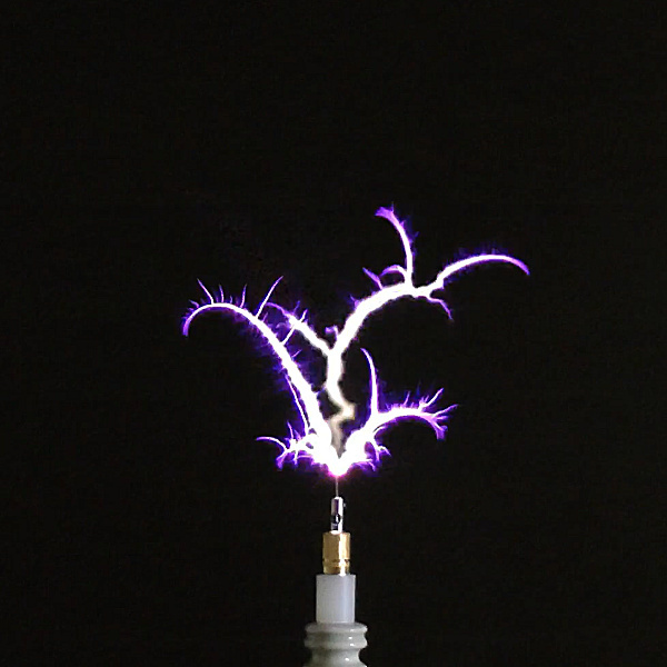
Fig 9.2. The classic fractal “fern” discharge at the centre of the lower parallel mode of coil 1 at 2.71Mc and 1.8kW, which generally shows a small number of well defined streamers, often with secondary and even tertiary tendrils emanating orthogonally from the primary. At this frequency the tendrils are small spread-out, less dense, and have lost that “ball” type of outer shell appearance seen in the previous upper parallel mode. Micro-filaments and the corona like bluish-hedge are very prevalent at this frequency, and also discharges have been seen to fit well into a number of different form categories, and also to display temporal based repetitive sequences, in the form of a “dance”. Primary streamers and sub-tendrils at this frequency are almost all entirely curved with an invisible spiral at the end, although there are the occasional straighter streamers with gradual curve.

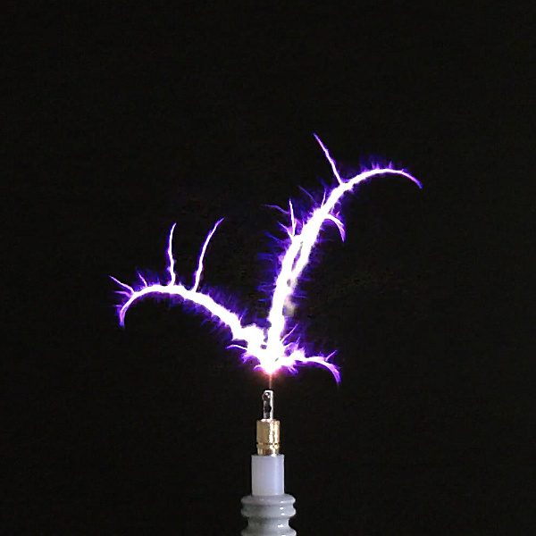
Fig 9.3. Still the classic fractal “fern” discharge at the upper parallel mode of coil 2 at 2.27Mc and 2.0kW. At this upper parallel mode there appears no real difference between the discharges of coil 1 and coil 2, and no measured or experimented evidence that the form of the discharge is about to change so dramatically at the lower parallel mode of the same coil.

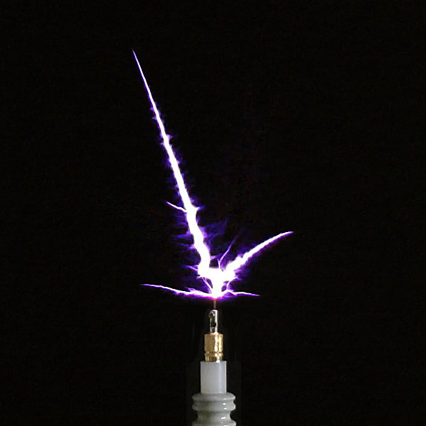
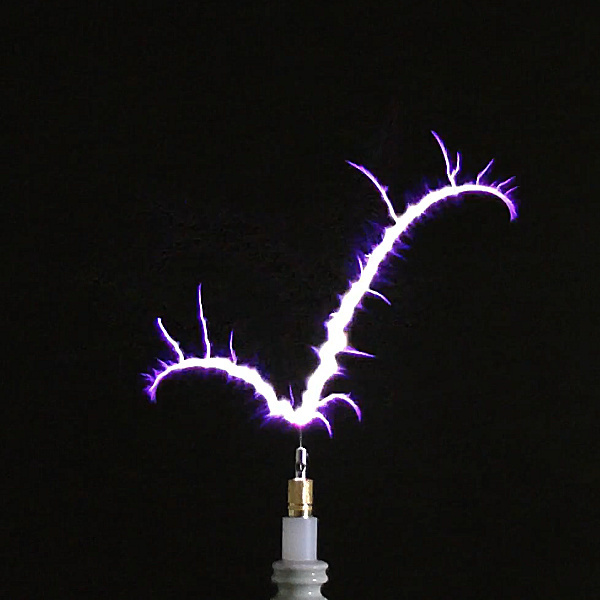
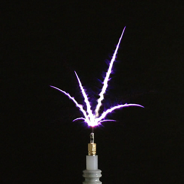
Fig 9.4. Now at the lower parallel mode of coil 2 at 1.71Mc and 2.1kW, we see the distinct transition from fractal “fern” to straight “swords”, or in this case straighter “swords”. At this transition frequency many of the swords still have a distinct curvature across their length from the breakout point. The “sword” type discharge has become more basic along its length, without secondary or tertiary tendrils, but retaining the micro-filament and bluish-hedge along the majority of its distance from the breakout point. Here the main central streamer is just starting to extinguish from the breakout point in what appears to be exactly the same mechanism as the fractal “fern” streamer. It is also noticeable that the straight “sword” is characterised by a very sharp single tip, whereas the fractal “fern” most often has a “feathered” final type with the multiple small ending points, or the possibility for splitting of the tip.

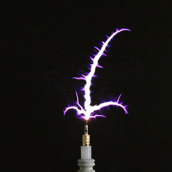
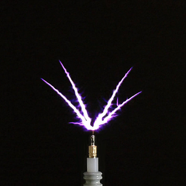
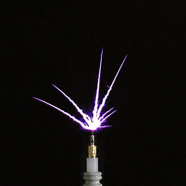
Fig 9.5. At the upper parallel mode of coil 3 at 1.35Mc and 2.2kW the “swords” have fully straightened along their length, still with a sharp single tip, and otherwise very similar characteristics to the lower parallel mode of coil 2 in the previous figure.

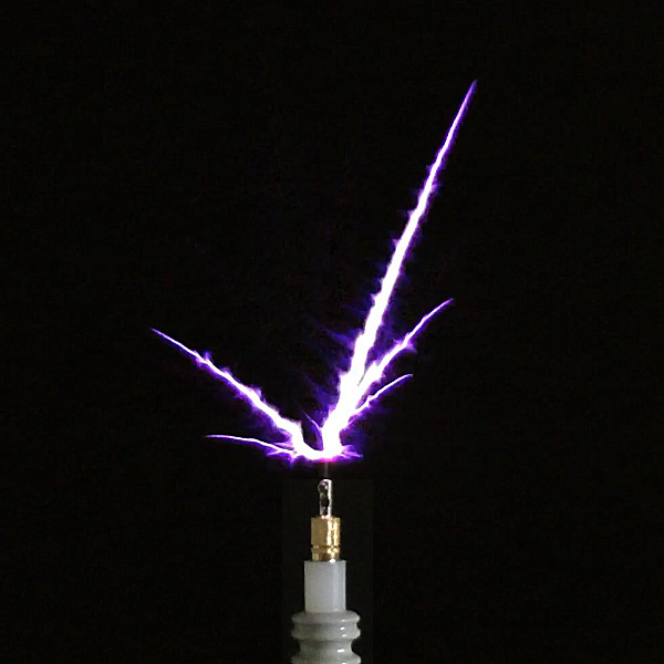
Fig 9.6. And finally at the lowest frequency in this reported experiment, at the very top-end of the lower parallel mode of coil 3 at 0.97Mc and 1.8kW, the primary streamers have become narrower and more sharp, with very little micro-filament and bluish-hedge detail along their length. These types of streamers now look very typical for a VTTC operated at around 1Mc with a tightly wound, high aspect ratio coil, with many densely packed turns of magnet wire. The streamers have lost almost all of the detailed features of the fractal “fern”. In fact, it would not be evident from this result that at higher frequency a completely different form of discharge is available from exactly the same apparatus, other than the winding of the secondary coil, and hence its designed wire-length and fundamental series mode resonant frequency.

Vibration, Quality, and Frequency

In this follow-up experiment we have looked to investigate in more detail what causes the fractal “fern” discharge and in particular how the discharge form changes with frequency. In the previous experiment in the series quite a few different variations were tested in order to discover the dependence on key system parameters such as the generator drive waveform, tuning and loading of both the primary and secondary coils, feedback and operating point of the oscillator generator, and even a different generator using wholly different vacuum tubes. These variations caused small changes in the operation range of the apparatus, but did not make an observed difference to the fundamental form of the discharge, in other words, the discharge was still fractal “fern” in nature.

In this experiment it is very clearly shown that frequency has a most significant impact on the discharge form. As many other variables in the experimental apparatus have been kept the same in order to not introduce unknown variations into the experimental method and results, it can be stated that frequency is so-far the most prominent parameter and variable with the most impact on the discharge, and particularly as a single Tesla coil, coil 2, was able to demonstrate both the fractal “fern”, and the “swords” discharge form, and some of the transition between these two forms. Maybe this implies that there is a significant difference when driving in the lower and upper parallel modes, but this appears not to be the case given that coils 1 and 3 showed little variation of discharge form between their lower and upper parallel modes, coil 1 with fractal “fern” in both, and coil 2 with “swords” in both.

We also see that the generator drive waveform also appears not to make a difference between fractal “fern” and “swords”, as in all driven modes the apparatus was carefully tuned through pick-up coil feedback, and grid bias and leakage, to make sure that the oscillating waveform in each of the secondary coils was a clean sinusoidal, without harmonics, and with minimal distortion due to clipping, saturation, and reflected power. Furthermore the ground system for the apparatus was consistent amongst all operation, and was also checked using the VNWA for any line resonance or harmonic characteristics in and around the operating frequency range. None were found, and there was no evidence of waveform distortion or non-linearity from the generator during the experimental operation. In fact the output of the oscillator generator was particularly clean all the way up to 3kW of utilised input power.

So all this care and attention to the experimental apparatus, method, measurement, and analysis, tends to indicate to me that the form of the discharge is fundamentally based on the inter-action between the dielectric and magnetic fields of induction in and around the experimental apparatus, and to the electrical and physical response or re-action of the common medium surrounding the Tesla coil, including the response of the materials and properties of the components used to make the Tesla coil. For example, the discharge requires a medium in order to form, in this case the air surrounding the coil. During the discharge breakdown of the medium forms a highly charged plasma “gas” around the breakout point. The characteristics and behaviour of this electrical plasma are then determined by the specific relationship between the dielectric and magnetic fields of induction surrounding the Tesla coil, and the form and nature of this discharge simply “follows” the relationship between the two induction fields, or said another way, “makes” the relationship between the two induction fields visible.

If we follow on from this conjecture, and bearing in mind the oscillator generator is a linear energetic excitation of the Tesla coil, rather than a disruptive non-linear impulse excitation, and the formation of a highly charged plasma “gas”at the breakout is a non-linear process, then we have the basis to further conjecture that the nature of the observed discharges are following a well defined linear sequence. It does not appear from all the measurements taken that the discharges appear like “random” trajectories through the common medium, as appears with natural lightning discharges, or from those generated from a spark-gap Tesla coil (SGTC), or well tuned dual resonance solid-state Tesla Coil (DRSSTC). The fractal “fern” has demonstrated spatial and temporal structure and geometry, ordered temporal sequence, and containing boundaries to the extent and extinction of the discharge. From this I conjecture that the fractal “fern” results from a more deeply rooted underlying vibration in the wheelwork of nature, a vibration that demonstrates defined qualities, or said another way a vibration in life composed of a distinct set of properties and principles.

And this is a most important distinction between vibration and frequency, where vibration is like a “tensor” combination of different fundamental qualities of life brought together or contained with a specific bounding or guiding purpose, whereas frequency is a “scalar” property which describes the rate of change of the vibration. So the vibration is the set of qualities that are being exposed by the discharge, and the frequency describes one property of this vibration. As the frequency changes so the quality and meaning of the vibration changes from one form to another. The vibration in turn determines or “guides” the relationship between the dielectric and magnetic fields of induction, and through the nature and form of the discharge we can visually observe the characteristics of the underlying vibration, as expressed through the electrical framework of the induction fields, and responded to by the physical action of the charged plasma “gas” created from the air.

If we accept this conjecture as a working hypothesis then it follows on that the detailed nature of the fractal “fern”, and for that matter the “swords” discharge, demonstrate details of all the underlying principles and properties that compose the collective vibration. So the trajectory of the primary streamers, the position and nature of secondary and tertiary tendrils, the asymmetry or symmetry of the discharge, the orthogonal micro-filaments, the bluish-hedge corona, the spiral or straight nature, and bifurcated or pointed end-tips etc. all represent interactive qualities within the expression of this particular vibration. Our job in uncovering the wheelwork of nature is to understand the purpose and meaning of the qualities at work, how they interact with each other, and how they form together as specific and different vibrations that express the diversity through the response of the common medium. This leads us squarely to the multidisciplinary approach to my research that is covered in much more detail on this website in the section on The Foundation for Toltec Research.

So, in summary to this discussion of the experiment in this post, it is conjectured that the scalar quantity frequency shows itself as a most important property of the guiding vibration determining the relationship between the dielectric and magnetic fields of induction, which is expressed through the electrical discharge form in the common medium surrounding a Tesla coil. When frequency is varied the nature of the vibration changes, and hence the form of the discharge changes to reflect a change in the underlying qualities of the vibration. The challenge stands to determine what the meaning of this is, and what specifically are the qualities that form the vibration being expressed, and the dependence on the inter-action with this vibration and the surrounding medium. All these areas needing considerable further consideration, investigation, and experimentation.

Summary Conclusions and Next Steps

Three Tesla coils have been used in this experiment to demonstrate that the fractal “fern” discharge changes to a “swords” discharge when the apparatus is kept constant, but the frequency of the secondary coil is varied from 3.4Mc down to 0.9Mc. The dramatic and spectacular change in the discharge form, combined with seemingly coherent spatial and temporal properties of the discharge, suggest as yet unexplored and undiscovered underlying principles and mechanisms within science, and the Wheelwork of nature. The challenge posed by the results of this experiment is to design further experiments to reveal more of the principles and mechanisms of the vibrations being expressed, and also to explore additional variations to the basic experiment that may provide more clues and evidence to confirm or refute the conjectures made so far. Next step experimental steps include the following:

1. Different generators should be tested with the same Tesla coil apparatus, including a spark gap generator, and linear amplifier generator to drive all five coils at the series fundamental mode.

2. A driven coil arrangement for the secondary coil only, with no primary coil, and hence simplifying the experimental apparatus and resonant interaction between the primary and secondary.

3. The introduction of non-linear impulse excitation to the Tesla coil to compare the effect of the linear and non-linear excitation waveforms, and their impact on the type of discharge.

4. The change of discharge in different surrounding gaseous mediums other than air. This might include discharge in a gas-filled vessels, plasma-like conduction experiments, and displacement of electric power experiments using high voltage impulse discharge.

Click here to continue to the next part, ESTC 2022 – Vector Network Analysis & Golden-Ratio/Fractal-Fern Plasma Discharges.


1. A & P Electronic Media, AMInnovations by Adrian Marsh, 2019,  EMediaPress

2. Dollard, E. and Energetic Forum Members, Energetic Forum, 2008 onwards.


Transference of Electric Power – Single Wire vs Telluric

In this new experiment on transference of electric power a comparison is made between power transfer through a single wire and through a telluric transmission medium, using a cylindrical Tesla magnifying transformer (TMT) apparatus. The TMT apparatus and linear generator is the same used in the High-Efficiency Transference of Electric Power series  both over 1.5m and 11m, and these new experiments are a continuation on those previously reported. This experiment is also the first in a new series on telluric transmission of electric power, and whilst I have experimented with telluric transmission over the years, none of this fascinating area of Tesla research has yet been reported here on the website. One of the pictures in the main slider at the head of this website shown here, shows telluric reception experiments made in 2017 at the upper parallel mode of a nominally 2Mc, 160m amateur band, flat coil. In the experiment reported in this post, the TMT transmitter and receiver are housed in different buildings of the lab, and can be connected by a 30m single wire, or a telluric channel ~18m point-to-point between the two ground systems, and 26m in total length including the cables. There is no special consideration of the ground/earth/soil between the two buildings, although the transmitter ground system used is specifically designed and constructed to provide a low impedance connection to ground.

Wireless transmission of power at a global level appears to have been one of Tesla’s greatest vision’s and endeavour’s, and one that he appears to have invested so much of his time, effort, and money. From early experiments in his New York laboratory, to larger scale experiments at Colorado Springs, to the grand-scale transmitter at Wardenclyffe, which unfortunately does not seem to have been operated in earnest before being dismantled. Tesla communicated this work mainly through his patents[1,2], demonstrations and presentations[3,4], and personal research notes[5]. In more recent years his life and work have been discussed and considered in a lot of detail, and there are many different perspectives online regarding all aspects of his endeavours, from whether there was/is any basis for this TMT system to work at all, all the way through to detailed analysis of how such a system was constructed, how it was intended to be operated, and the kind of results that could be accomplished in power distribution through this method. What is much more rare is solid experimental evidence, measurement, and subsequent consideration and analysis of what can be experimentally accomplished in transferring power between a transmitter and receiver in a TMT arrangement through the earth. This specifically includes what power levels can be transferred over what distance, at what frequencies, with what level of losses, and through what transmission principles and modes, and in addition, what the impact of this would be for the surrounding environment and life in general.

What follows are my own considerations and perspectives on Tesla’s Wireless Power, and what I feel are some of the most important considerations for these types of experiments. I will over a series of posts be demonstrating aspects of these principles, and looking at the type of results that I have been able to accomplish so far in this field. For me, Tesla’s “wireless” power as a description of the field is somewhat misleading, as in my perspective it never really was “wire-less”, in other words it never involved no “wires” between the transmitter (TX) and receiver (RX). By this I mean that the TMT apparatus, to transfer even the tiniest amounts of power between TX and RX, requires a single transmission medium of lower impedance than the pervasive surrounding medium, and connected from the TX secondary coil lower-end, to the RX secondary coil lower-end. So if we assume that the pervasive surrounding medium is air, then the single transmission medium of lower impedance might include, for example: a single metallic wire, a telluric channel through the ground, or even a gas discharge tube that has been ignited by the potential gradient across the Tesla coil secondary. If this single transmission medium is not present then only minute levels of power can be transferred between the TX and RX, consistent with transverse electromagnetic propagation from a radio transmitter to a radio receiver.

I could conjecture that Tesla may have seen his TMT approach to power distribution as distinctly “wire-less” when compared to other electrical systems of the time, like Edison’s DC power distribution, that required two conductors to make an electric circuit between the generator and load, and hence the normal losses that occur in a closed loop electrical circuit. In simple comparison, Tesla’s system appears as an open loop electrical circuit relying on the potential gradient of the “cavity” established across the secondary coil of the TX, the transmission medium, and the secondary coil of the RX. In this cavity it has been suggested that a different mode of transmission can be established, the longitudinal magneto-dielectric (LMD) mode, which is again distinctly different from the transverse electromagnetic (TEM) mode, and in principle can lead to very high-efficiency of power transfer, over very large distances, and with very low losses. These modes have been proposed and explored in detail by electrical researchers such as Eric Dollard[6-10] , and other aspects of wire-less power by researchers including Tucker et al.[11] and Leyh et al.[12], and also in my own experiments in the Transference of Electric Power series on this website.

Another important aspect that has been widely discussed is the requirement for the ground systems used at both the TX and RX in a TMT system, to present the very lowest impedance possible, or resistance at resonance, to connection of the TX and RX coil to the telluric channel. This would appear to be common sense, at least for the TEM transmission mode, where the lowest losses in the system will occur when the impedance of the ground connection at the TX and RX are at their lowest, combined with the lowest impedance of the single transmission medium between the two. However, this is not necessarily the case for the LMD mode, where in my own experiments and particularly the first in the sequence on High-Efficiency Transference of Electric Power, it is demonstrated that the efficiency of the power transfer increases as the impedance of the single-wire medium increases. In particular it was demonstrated that more than 500W of power can be transferred through a single wire no thicker than a human hair, a 40AWG (0.08mm or 80 microns) nickel plated copper wire, where the power transfer efficiency could be measured up to 100% according to the limits of experimental accuracy of the measurement equipment.

It was suggested in this previous experiment that … “Power transfer of this order through such a thin wire is possible as the dielectric and magnetic fields of induction are contained or guided around the single wire. Removal of the single wire from the receiver end prevents any power transfer to the receiver, which shows that when driven by a linear sinusoidal generator, a lower impedance transmission medium, (in this case the single wire), is needed to guide the induction fields between the transmitter and receiver coils.” So in principle it could be conjectured from this unusual result with a very fine single wire, that provided the correct LMD mode is arranged in the cavity of the TMT system, the lower impedance of the ground system may not be as important as previously suggested. Certainly for the TEM mode in the transmission medium large losses will occur from higher impedance connections and the single wire medium itself, as well as radiative losses along the length of the single wire, and reflections from impedance mismatches and transitions across the cavity. From my results I conjecture that the combination of the TEM mode in the TX primary, LMD mode in the cavity formed by the TX secondary, transmission medium, and RX secondary, and the TEM mode in the RX primary, leads to the highest efficiency in the transference of electric power, and is discussed in detail in High-Efficiency Transference of Electric Power – 11m Single Wire.

The LMD mode also removes the requirement for every part of the TMT system to be in principle at the same resonant frequency. It seems to be widely thought that the highest efficiency of transmission of power takes place in a TMT system when all the sections are arranged to resonate at the same frequency, hence forming one continuous minimal impedance coupled resonator system. Whilst again this would most likely be the case for the TEM mode, from my own measurements it is not so for the conjectured LMD mode. I have measured that at highest efficiency of power transfer the LMD mode in the single-wire is not the same frequency as that measured in the primary of the TX or the RX. Furthermore, there is spatial coherence of the LMD mode but not temporal in the cavity. In the TEM mode there is temporal coherence across the cavity but not spatial, measured, presented and considered in detail in Transference of Electric Power – Part 1. These experiments and their results, suggest that there are significant differences between the TEM and LMD modes, and how a TMT system performs when it is arranged to operate in one mode or the other, or in a combination of both modes, which I conjecture and have in-part confirmed through measurement, is actually the optimum arrangement for the highest efficiency of power transfer.

This experimental post consists of two video experiments one based on a single-wire 30m TMT system, and the other with the same TMT system connected by a telluric channel. Telluric is often used as a description of the transmission medium in Tesla research when the ground/earth/planet is used to form the “single wire” and hence the cavity between the TX and RX. In this case the impedance of the Telluric channel is much higher than that of the single metallic wire, and hence we make a comparison as to the likely power that can be transferred through the channel, what modes of transmission are involved in the system, and what the magnitude and mechanisms of the losses are involved in the channel. The generator used in both experiments is the same linear amplifier generator featured in the High-Efficiency Transference of Electric Power series, and is explained in detail in those posts, and is used to drive the TMT system at the fundamental series resonant mode. In addition to measuring power transfer in both mediums, the small signal impedance characteristics of the TMT system are measured, and then tuning and matching the generator to the apparatus to ensure maximum power transfer to the experiment with the minimum losses.

The first video experiment of a cylindrical TMT system with a 30m single wire demonstrates and includes aspects of the following:

1. A Cylindrical TMT experimental apparatus using a 30m single wire transmission medium between the transmitter (TX) and receiver (RX) coils.

2. Setup, matching and tuning, and operation of a 1kW linear amplifier generator, adjusted to drive the TMT experiment at the available series resonant modes, and further adjustment during operation to maximise the power transfer efficiency, and minimise reflected power.

3. Small signal ac input impedance characteristics Z11 from the perspective of the generator, and showing tuning of both the series and parallel resonant modes to establish optimum experimental starting conditions.

4. At 1.920Mc using a balun feed to the transmitter the maximum power transfer efficiency was measured at ~ 34%.

5. At 1.890Mc without using a balun feed to the transmitter the maximum power transfer efficiency was measured at ~ 40%. This frequency and drive method produced the highest efficiency observed during the experiment.

6. The optimum power transfer was accomplished with the maximum number of four primary coil turns, and balanced parallel modes, at both the TX and RX coil.

7. Extension of the single wire from 30m to 40m, close to the quarter wavelength of the generator drive frequency, did not change the maximum measured power transfer efficiency of ~ 40%.

8. It is discussed and conjectured that the TEM transmission mode is dominant in the experimental setup, and as a result large losses occur through radiation from the single wire.

9. It is conjectured that the LMD transmission mode was not adequately established in the single wire over 30m or 40m, and hence the much lower power transfer efficiency than expected from previous experiments with 1.5m and 11m single wires. In previous experiments with an 11m single wire transfer efficiencies up to 96% were measured, and it was conjectured that the LMD mode was adequately established as the dominant transmission mode.

Video Viewing Note: The video control bar has a “Settings” cog icon where you can select video quality, which by default is set to “Auto”. For clear viewing and reading of the VNWA software characteristics and text on the computer screen, “1080p” video quality is recommended, and may need to be selected manually from the settings icon once playback has started.

The second video experiment of a cylindrical TMT system with a telluric channel demonstrates and includes aspects of the following:

1. A Cylindrical TMT experimental apparatus using an 18m Telluric transmission medium between the transmitter (TX) and receiver (RX) coils.

2. Setup, matching and tuning, and operation of a 1kW linear amplifier generator, adjusted to drive the TMT experiment at the available series resonant modes, and further adjustment during operation to maximise the power transfer efficiency, and minimise reflected power.

3. A custom ground system, using copper water pipes driven into the ground, and consisting of a main RF ground and a reference test ground.

4. Small signal ac input impedance characteristics Z11 from the perspective of both the TX and RX, and showing tuning of both the series and parallel resonant modes to establish optimum experimental starting conditions.

5. Large signal tuning using a small breakout flair at the top of the telescopic tuning aerial attached to the top-end of the TX secondary coil.

6. Signal reception tuning, using a Sony ICF-2001D radio scanner, to calibrate the proportion of signal transmitted through the radio-wave and the telluric-wave from the transmitter to the receiver.

7. At 1.860Mc 10W of input power at the TX resulted in ~0.55mW via the radio-wave, and ~0.7mW via the telluric-wave, and a total of ~1.25mW at the RX coil, into a HP435B power meter with an 8481H 3W thermocouple power sensor.

8. At 1.860Mc 500W of input power at the TX resulted in a total of ~80mW at the receiver through the radio-wave and telluric-wave combined.

9. It is discussed and conjectured that almost all of the transmitter power is absorbed into the earth around the ground system, and radiated from the secondary coil in the TEM transmission mode. This diffuse absorption and radiation around the transmitter system results in very little power incident on the RX system, and hence at 1.860Mc in the 160m amateur band, radio communication appears possible through the telluric system, but significant transference of electric power does not appear possible at this frequency.

Video Viewing Note: Again “1080p” video quality is recommended, and may need to be selected manually from the settings icon once playback has started.

Figure 2 below shows the schematic for the experimental apparatus used in the video experiments. The high-resolution version can be viewed by clicking here.

Experimental Apparatus and Operation

The schematic and principle of operation for the experimental apparatus used in the video experiments is a variation to that used in the High-Efficiency Transference of Electric Power series. Much of the equipment used, and a detailed explanation of the linear amplifier generator are covered in that series of posts. The power measurement meters have been changed from the Bird 4410A analogue thruline power meters, and replaced with 4391A digital readout thruline power analysers. The digital readout of the Bird meters makes them easier to read both during the experiment, and on the video. The 4391A power meters were both calibrated using the same inline method previously presented, at 500W input power for direct comparison on a single range, and with a limit of experimental error of <0.5%. User uncertainty and errors in reading the analogue dial during the experiment is further reduced through using the digital readout. The other significant measurement additions are for the telluric transmission experiments where the received powers are much smaller and hence different instruments have been used. Radio signal strength is measured using an Sony ICF-2001D radio scanner, which has been adapted to allow for a direct BNC input for external antenna connection, as well as the integral telescopic aerial mode. Direct received power levels are measured using a Hewlett Packard HP 435B power meter with a HP 8481H 3W thermocouple power sensor.

As demonstrated in the video the 30m single wire transmission experiment is initially setup using the VNWA and these results are discussed below. This provided a tuned starting point for the complete TMT system, where the TX and RX coils are arranged to resonate at the same frequency. The fundamental series resonant mode was initially set at 1.92Mc, but then subsequently empirically adjusted to 1.89Mc for slightly increased transfer efficiency across the single wire. The parallel modes of both the TX and RX coils were balanced, using their primary coil tuning capacitors, to equal magnitude of impedance, before connecting the 500W load to the RX coil output. Care was taken to keep the operating frequency of the TMT system within the 160m amateur radio band, and also where the lab is in a remote setting to minimise any operation interference on adjacent radio bands. With the initial conditions set the power was increased gradually from 10W up to over 500W, whilst minimising any reflected power back to the linear amplifier by adjustment of the Palstar antenna tuner. In this way power could be passed to the transmitter across the 30m single wire and into the receiver to power the load.

It is important to note from the generator tuning and operation in part 1 of the video experiment the differences that arise in power measurement at the linear amplifier output, (as measured by the MFJ-998), and that measured at the input to the TX coil by the Bird 4391A. The 4391A measures forward and reflected power right at the input to the primary coil which depends on  the match between the antenna tuner output impedance and the TX input impedance. At resonance the input impedance of the TX coil is predominantly resistive and the SWR as measured by the 4391A varied in the range 1.5-2.7 dependent on the fine tuning of the antenna tuner. The power measured at the output of the Kenwood linear amplifier by the MFJ-998 is now on the input side of the Palstar antenna tuner, where the tuner is transforming the impedance of the TX coil to be as close to 50Ω as possible, minimising reflected power back to the linear amplifier, and allowing maximum dynamic range and output power utilisation from the linear amplifier. So when the MFJ-998 SWR is minimised in the experiment as close to 1.0 as possible, the MFJ-998 is used to measure the power supplied from the linear amplifier into 50Ω impedance, and the 4391A is user to measure forward power into the impedance presented by the TMT system at its primary coil input at the TX. These two meters will then read a different power when at the minimised SWR of the linear amplifier, and will read more closely the same as the SWR is detuned at the antenna tuner to correspond to the TMT input impedance.

For consistency in experimental measurement of the input power and output power of the TMT system the forward power measured both by the 4391A at the TX, and the 4391A at the RX was used to assess the power transference efficiency across the TMT system. This was then compared at two tune conditions of the antenna tuner, firstly when minimising the SWR presented to the linear amplifier which leads to different power readings on the MFJ-998 and TX 4391A, but minimal reflected power at the linear amplifier output. The second with detuned SWR between ~ 1.5-1.9 presented to the linear amplifier which leads to close match between the power readings on the MFJ-998 and the TX 4391A, but with slightly reduced efficiency and increased reflection at the output of the linear amplifier. As demonstrated in part 1 of the video, the experiment was initially operated using a 1:1 current balun at the output of the 4391A in order to properly convert the output from the unbalanced output of the generator, to the balanced input condition of the primary coil. However this appeared to reduce power transfer efficiency by up to 5% and was subsequently removed from the experiment when it was empirically retuned to 1.89Mc.

For the telluric measurements where the RX coil is not visible to the TX VNWA measurement the initial tuned conditions were set to 1.87Mc using the VNWA small-signal fundamental series mode of the TX coil connected to the telluric ground system. This was slightly empirically adjusted to 1.86Mc when tuning using the large-signal generator drive, and corresponded with the maximum neon brightness at the top-end of the TX secondary coil. A small breakout flare was generated at high TX input power > 700W which also was maximised around 1.86Mc. Care needs to be taken only to use this as a large-signal tuning check, as any breakout at the top-end of the secondary coil will reduce the top-end impedance of the coil to the surrounding-environment effectively increasing the quarter wave length of the coil, and hence reducing the series resonant frequency of the TX coil. By both empirical tuning methods 1.86Mc was determined to be the optimal large-signal generator driving frequency to the telluric connected TX coil with 39cm defined telescopic aerial extension. This tuned telluric experimental frequency keeps all the experiments in the 160m amateur band with a very high-Q TX and RX coil, and hence very tightly contained transmission bandwidth using only CW and morse-code for radio call-sign identification.

Another key measurement in the telluric experiment which needs some consideration is the process of measuring the radio-wave of a radio transmission. For all radio transmission, and as transmitters are almost always grounded down to earth, there major component of the transmission, that is the propagating TEM wave from the radio transmitter antenna to the receiver antenna. In relation to the telluric part of this experiment, we cannot assume that all the power transferred from the TX to the RX coil is via the telluric channel through the ground, as there will also be a radio-wave component at the receiver. We also cannot simply remove the bottom-end ground connection of the RX coil to measure the this radio-wave component, as this will change the wire-length of the secondary cavity, and hence change its fundamental series resonant frequency, and any connected receiver which is tuned to the transmitter frequency will erroneously show no received signal, simply because the RX coil is not correctly tuned to the transmit frequency.

To accomplish the radio-wave part of the experiment, and as demonstrated in part 2 of the video experiment, the telluric ground connection is removed from the RX coil, and is replaced with a single wire 10m in length which is NOT connected into the ground or to any other grounded end-point. The telescopic aerial at the top-end of the RX coil is now fine adjusted so that the series mode resonant frequency of the RX coil matches the transmit frequency. This is accomplished by maximising the received signal at the receiver at the correct TX frequency, and then cross checked by VNWA measurement to confirm correct tuning of the RX coil. In this way the RX coil is now tuned to the correct frequency for receiving the transmitted signal, but is also not connected in any way to the ground. The signal strength now received on the radio receiver, or power meter, is a result of the radio-wave contribution only, and is less than the combined radio-wave and telluric-wave, as can be seen in the video experiment. The proportion of radio to telluric wave can also give a good indication as to the dominant transmission mode involved in the transference of electric power between TX and RX coil. Equal radio and telluric components tend towards a dominant TEM mode of propagation between the two, or with a combination of TEM and LMD, with the TEM mode dominant. A much larger telluric wave can indicate a dominant LMD mode, and this will be demonstrated in the Telluric Transference of Electric Power series. In this experiment the radio-wave and telluric-wave contributed about equal proportions of the received power in the telluric part of the experiment.

Figures 3 below show a range of pictures of the experimental apparatus, measurements, and some of the key setup conditions for both the single wire and telluric experiments. It is interesting to note that in fig. 3.3 the phone on the top of the MFJ-998 shows the live image of the remote camera setup in lab2 to monitor the RX coil and apparatus. The remote camera is connected through local WiFi in lab2, and then to the router in lab1 by wired LAN connection between the two labs. This live remote video monitoring allows operation of the TX system whilst monitoring directly the RX system, and to produce the live inset video in both parts 1 and 2 of the video experiments.

Telluric Ground System Design and Construction

The ground system associated with a TMT system has always been considered as a critical part of the engineering required to make a successful telluric transmission system, with minimal losses and maximum transferred power between the TX and RX coils and the telluric transmission system. Tesla himself noted that it is necessary to get a firm grip on the ground if it is to be resonated by his wireless power system, and a lot of effort was poured into minimising the impedance, or resistance at resonance, of the connection between the ground electrode and bottom-end of the Tesla coil[5]. Subsequently in conversations with Eric Dollard he has pointed out that it is imperative to get as much copper into the ground as possible for any telluric experimentation and get as close to 0Ω as possible, in other words, to minimise the contact resistance of the Tesla coil secondary bottom-end to the transmission medium in the ground. In addition for a true Tesla transformer, as the bottom-end of the secondary is connected to ground by the minimum impedance possible, the top-end of the secondary needs to present the highest possible impedance of the coil at an elevated position above the ground, and preferably with a top-end load such as a metal sphere, ball, or toroid.

Arranged in this way, and according to conjectures and postulation on the LMD mode,  the Tesla transformer ot TMT system forms a complete longitudinal cavity from the high-impedance top-end of the TX coil, through the telluric transmission medium, and up to the high-impedance top-end of the RX coil. It is in this condition that the coherent LMD mode facilitates the very high efficiency transference of electric power between the generator and the load. The Tesla transformer also fulfils the key step of transforming the TEM mode in the primary to the LMD mode in the secondary cavity, meaning that the generator TEM mode is transformed to LMD mode in the single wire or telluric cavity, and then back again to the TEM mode in the primary of the receiver. It is conjectured that the LMD, or longitudinal mode as it is often referred to, forms a standing wave across the cavity with one or more defined null points  in the cavity, and hence as such, is not subject to the same losses as a propagating transverse electromagnetic wave. Some of my own experiments in the Transference of Electric Power series, and the High-Efficiency Transference of Electric Power series, appear to support the existence of the LMD mode, and that indeed very high power transfer efficiency can be established between the TX and RX coils of a TMT system in the close mid-field region.

It remains to be experimented and tested to see if this LMD conjecture can be extended across far-field distances and does indeed result in lower power transmission losses, and hence higher efficiency of power transfer. As a point to note, I do also myself debate the necessity for the lowest resistance connection to ground when the LMD mode is properly established. The coherence across the entire cavity of the LMD mode should not necessarily require a low impedance connection to ground, or even a low impedance telluric transmission medium. This would certainly be necessary if the transmission mode is by TEM propagation, where any higher impedance, mismatch of impedance, absorption and reflection of power, and radiation losses will make for huge loss of power across the distance of the transmission medium. All these factors are certain for TEM power transmission, but not all may apply for a coherent LMD mode properly established over the transmission cavity. This conjecture remains to be confirmed or refuted through experimentation.

Accordingly in my own experiments, and as a starting point for my telluric experiments, I designed and constructed a ground system within the available space, materials, and budget that are accessible to me at this time. From the perspective of getting as much copper into the ground or the lowest resistance to ground, this appeared as the best place to start, that is, to enable maximum possibility of receiving a signal through the ground at distance whether it be by TEM or LMD transmission modes, or a combination of both. The design uses 22mm copper water pipe which gets a good quantity of copper into the ground, and with reasonable surface area, by simply drilling holes and driving in tubes, as opposed to having to dig or excavate large pits in the ground. The essence of the water pipe is that at any time water can be piped through the ground system and down to where the contact between the copper and ground is actually occurring. In addition small holes where drilled along the length of the underground copper pipes to allow water to escape along the length and hence irrigate the soil around the pipes extend into the ground as well as at the end of the pipe. This gives the possibility to prepare the ground system before experiments to irrigate the surrounding underground earth and reduce the ground system resistance to the earth to as low as possible. This water irrigation works well as intended, and after about 1 hour of irrigation the ground system impedance falls significantly.

In order to make measurements of the ground system performance I included a single copper pipe reference where I can measure the impedance between the main ground system and the reference ground system. As this experiment is an introduction to my telluric experiments so far, I will include these measurements in the start of the reported series on Telluric Transference of Electric Power. The preparation of the ground system involves connecting the reference ground to the main ground via plastic water hose, and then first connecting the top-end of the reference to the main water supply. This quickly allows water to flow into an fill up all the pipes in the system, and before the water has a chance to soak away from the ends and through the holes into the surrounding earth. When this is done the water direction is then reversed to fill from the bottom-end connection of the main ground system and left for up to an hour to back-fill all the pipes, soaking away into the ground and reducing the contact resistance between the earth and the copper. The total exposed (above ground) length of the main system is 3m, and the underground copper is ~ 15m. The total physical size of the ground system is less than one-tenth of the wavelength of the generator at the 160m amateur band.

The main and reference system have a copper electrical feed point which is soldered into intimate contact with the copper pipework and does not disturb the water flow within the pipes. The main system is connected by a 4m 0AWG micro-stranded silicone coated cable to the lower end of the TX secondary coil, and for the reference to measurement equipment via a 4m 12AWG micro-stranded silicone coated cable. With irrigation for ~ 1hr, and in the winter months with good rainfall, so the water-table is at its maximum in the area, the impedance of the main ground system to the earth can be as low as ~ 15Ω @ 1.86Mc. The total impedance of the main ground system, as measured with the reference system, and including the 4m 0AWG ground cable between the bottom-end of the secondary and the ground system terminal, is ~ 40-60Ω @ 1.86Mc, dependent on season and irrigation. This is approximately one-third to one-half of the resistance of the secondary coil at resonance, and as such presents a reasonably low and solid connection for the TX coil to ground at the frequency of operation, and was practical to construct and build in the space available. I would have preferred a centre fed star arrangement for physical construction, consistent with many preferred ground system arrangements used by radio amateurs in the MF and HF bands, however my available space did not allow for this, and I adopted a straight design with the same amount of copper underground. All in all the ground system so far has proved to be effective, and I have been able to measure telluric transmission of power and signals over significant distance from the transmitter, which will be presented in the Telluric Transference of Electric Power series.

It should also be noted, and as indicated in the schematic in fig. 2, that the linear amplifier generator is NOT connected itself to the RF main or reference ground system used in the telluric experiments. This is arranged in order not to introduce uncertainty into the source of any measured telluric transmission through the earth. For generator safety during operation the equipment and components of the generator are connected together by their earth chassis connections and then in-turn connected to an isolated line supply earth. This continues to protect the generator equipment and components in the event of an electrical fault, whilst isolating the earth connection from the telluric RF ground system, and hence not influencing or confusing the measured results.

Figures 4 below show pictures of the final main and reference ground system outside lab1, and some from its construction in 2019. For the telluric comparison in this experimental post lab2 uses a dedicated RF ground through a single copper coated steel ground rod, and is typical for use in amateur radio work when connecting a linear amplifier transmitter and receiver. Clearly in this experiment the TX and RX ground systems are quite different in size, copper under the ground, and hence contact resistance between the telluric transmission medium and the RX coil.

Small Signal AC Input Impedance Measurements

Figures 5 below show the small signal ac input impedance Z11 measured directly on the experimental system, and using an SDR-Kits VNWA vector network analyser, as used on many experimental pages on this site. The measurement setup, equipment, and connection to the experimental apparatus is shown in fig. 3.2.

To view the large images in a new window whilst reading the explanations click on the figure numbers below.

Fig 5.1. Shows the input impedance Z11 over the range 100kc to 5Mc for the TX coil primary connected to the VNWA, and with balanced parallel modes with the primary tuning vacuum capacitor set to 396pF. The bottom-end of the secondary coil is connected directly to the main ground system as would be the case in the telluric experiments, and the top-end telescopic aerial is set at its default length of 39mm that sets a wire-length that corresponds to ƒS = 1.87Mc @ marker M2 for the fundamental series resonant mode. This same point was empirically adjusted to drive at 1.86Mc for optimum large-signal tuning. The TX coil resistance at the series mode M2 presents a resistance of 24.1Ω which is conveniently very close to one-half of the optimum generator system output impedance of 50Ω. This could ideally be connected to the generator directly using a high-power 1:2 current balun with minimal if any antenna tuner transformation to the linear amplifier. For flexibility in tuning for this experiment the Palstar antenna tuner was used directly to transform the 50Ω output of the linear amplifier to the 24.1Ω at the TX coil primary input. The lower and upper parallel modes from the TX primary and secondary coil are impedance magnitude balanced, with lower mode ƒL = 1.62Mc @ M1, and the upper mode ƒU = 2.24Mc @ M3. It should be noted that the RX coil for this measurement is also connected and correctly tuned to its own ground system at lab2 in the reciprocal arrangement, but cannot be “seen” at all in this VNWA measurement.

Phase change is consistent with a typical high-Q, loosely coupled and loosely wound, Tesla coil, and the series and parallel modes all occur at a phase angle of ~ 0° consistent with a resonant circuit mode. This characteristic presented in fig. 5.1 forms the base small-signal impedance characteristic for the telluric experiment presented in this post, and also for experiments presented in the Telluric Transference of Electric Power series in the 160m amateur band in the MF band. Lower frequency telluric experiments in the LF band have very different characteristics and will be presented in future posts. For best match to the linear amplifier generator the fundamental series mode ƒS is used as the optimum driving point where most power can be coupled directly into the secondary cavity. At the receiver in telluric experiments both the series and lower parallel mode can be tuned to the 1.86Mc and both are useful for different aspects of the measurement. For signal strength experiments using the radio scanner the parallel mode is best as it presents a high-impedance to the output of the RX coil, which is well suited to maximum incident voltage at the input to the radio tuner. For absolute power measurements using a 50Ω power sensor, in this case the HP 435B with HP 8481H sensor, tuning the RX coil to the series mode is necessary for making power measurements, where the transfer of power between the RX coil and sensor input impedance is best optimised.

Fig 5.2. Shows the characteristics for the complete TMT system connected by the 30m single wire, and without the 500W load connected at the primary of the RX coil. The low impedance of the single-wire transmission medium allows the VNWA to “see” the characteristics of the RX coil reflected into the input impedance measurements. This is particularly useful to accurately setup the TX and RX coils, at least for the TEM modes, where their fundamental series resonant modes can be matched, and the parallel modes can also be matched. Here in this characteristic the parallel modes are shown as balanced, and the series mode is that of the TX coil dominant at ƒS = 1.88Mc @ M4. The system is unloaded at the RX coil and hence this is the highest-Q measurement of the TMT system, where the parallel modes at both the TX and RX are very sharp and also split to give two peaks at the lower mode, and two peaks at the upper mode. The primary tuning capacitors CPTX = 354pF and CPRX = 498pF have been adjusted to bring about the best empirical balance between the parallel modes, and hence equal influence of the parallel modes in all four coils, two primary coils, and two secondary coils. I have discussed and conjectured in Cylindrical Coil Input Impedance – TC and TMT Z11 that balance of these four parallel modes in a TMT system is the optimal starting point to maximise the generation of the LMD mode across the TMT cavity, and that the LMD mode can be further fine tuned by adjusting the parallel modes at both the TX and RX coil.

It should be noted that the frequency split in the upper and lower parallel modes is quite narrow, (as compared to say the TMT system measured in the close mid-field region in High-Efficiency Transference of Electric Power over 1.5m, and show in fig 3.2), which shows the reduced coupling between the TX and RX coil over the longer distance of the 30m single-wire. Over the 1.5m single-wire the lower parallel modes where split by ~ 70kc, whereas here they are split only by 30kc. There are also low impedance series points at M2 = 1.66Mc, and M6 = 2.32Mc which could be alternative driving points for the linear amplifier generator. Both points have significantly higher impedance presented to the generator, and hence M4 remains the best point to drive the TX coil for maximum transference efficiency across the TMT.

Fig 5.3. Here the 500W load has been connected at the output of the RX coil primary, and the series fundamental modes have been finely tuned and balanced using small changes in wire-length affected through the telescopic aerial at both the TX and RX secondary coils. The final tuned lengths of the aerials are TX = 39cm, and RX = 37cm, and these were used as the base tune when needing to reset to a known starting condition. Adding the 500W load has collapsed the parallel modes at the RX coil, although of course they remain part of the actual electrical system at the receiver. The close tuning of the series modes leads to frequency splitting through beat frequencies between the two resonators which results in the double phase relationship seen at markers M2, M3, and M4. Two fundamental series resonant modes, and upper and lower, are now present at ƒSL = 1.85Mc @ M2, and ƒSU = 1.92Mc. The upper series mode formed the starting frequency for the 30m single wire experiment where the input impedance is resistive, RSU = 51.5Ω @ M4 and very close to the untuned system output impedance of the linear amplifier generator at 50Ω. This driven point was subsequently moved to M3 at ƒS = 1.89Mc which yielded a slight increase in transfer efficiency. The parallel modes of the TX coil remain largely unaffected by the split series modes and are balanced with slight adjustment to CPTX = 371pF.

Fig 5.4. Here the matched series fundamental modes have been detuned by increasing the wire-length using the telescopic aerial at the TX coil from 39cm to 50cm. This reduces slightly the lower series frequency, ƒSL = 1.82Mc @ M2, which then becomes the dominant mode with respect to the generator drive. This dominant series mode reduces the input resistance of the TMT system, RSL = 35.2Ω @ M2, and slightly imbalances the parallel mode tuning at M1 and M5.

Fig 5.5. Here the matched series fundamental modes have been detuned by reducing the wire-length using the telescopic aerial at the TX coil from 39cm to 17cm. This increases slightly the upper series frequency, ƒSU = 1.96Mc @ M4, which then becomes the dominant mode with respect to the generator drive. This dominant series mode reduces the input resistance of the TMT system, RSU = 26.9Ω @ M4, and slightly imbalances the parallel mode tuning at M1 and M5, the other way from fig. 5.4. It should be noted that the centre drive point of the upper and lower series modes at M3 remains less impacted by the frequency detune of the series modes, and hence represents the optimal stable drive point over the dynamic range of the experiment with ƒS = 1.89Mc @ M3. The higher impedance of point M3 requires further tuning using the antenna tuner, or is also suitable for 1:4 current balun at the input to the TX primary coil.

Fig 5.6. Shows the effect of increasing the single wire length from 30m to 40m, which also makes the single wire almost exactly a quarter wavelength of the generator drive frequency. The increased wire-length in the cavity has increased the overall wire-length of the TX and RX coils at their bottom-ends, and hence the five resonant points of interest indicated by markers M1-5, have all shifted down slightly in frequency. The centre drive point at M3 now being at 1.86Mc rather than at 1.89Mc. Otherwise the TMT system impedance characteristics remain largely unchanged, and the quarter wavelength length of the single-wire does not have such a big impact as might be at first expected given the complete impedance transformation from a short circuit to open circuit across a quarter wavelength wire. And this is an important point to note, that the length of the cavity is now defined by the quarter wave TX and RX coil plus some of the wire-length at the bottom-end and the top-end that is within the magnetic coupling distance of the coil. For example, if we take just the TX coil and add a single wire at its bottom-end of say 1-2m, this will have a very distinct change on lowering the fundamental series mode frequency ƒS. If we now add a further 5m to the single-wire this further reduces ƒS, but not to the same amount. Adding a further 10m has even less impact on reducing ƒS.

So the impact of adding single-wire length to either end of the coil has diminishing impact to ƒS with increasing length, and this is the product of the wire-length which is within the magnetic field coupling of the coil. And this is what is happening with the increase in single-wire from 30m to 40m. Only the wire length up to about 5m from the bottom-ends of the TX and RX coil have a significant impact on reducing the ƒSL and ƒSU, whilst the 20 or 30m in the middle makes much less difference to the TEM frequency characteristics of the TMT system. So increasing from 30m to 40m single-wire is not really about the quarter wavelength impedance transformation, but rather simply an increase to the middle section of the transmission medium, with only slight impact on the frequency of the five resonant points of interest. This would continue for increasing length of single-wire with diminishing impact on the frequency characteristics until the TEM losses along the wire length collapse the coupling of TX and RX coils.

Single Wire Comparison at Lengths 1.5, 11, and 30m

In this experiment with a 30m single wire in the TMT cavity the best result obtained at 1.89Mc was 200W supplied by the RX coil to the load, for 500W supplied to the TX coil by the generator, yielding a power transfer efficiency of 40%. This is very much lower than that obtained for the 1.5m @ 99%, and 11m @ 96% in the High-Efficiency Transference of Electric Power series. The biggest loss mechanism in this experiment is expected to be radiative losses from the single wire, as the single-wire did not heat up, and the components at the TX and RX did also not heat up. Some power would have been lost in resistive losses along the single-wire length, but the majority of the power would have been radiated from the single wire acting as a long-wire antenna between the two coils. This means that the TEM mode was the dominant transmission mode in the cavity, whereas it has been conjectured in the 1.5m and 11m single-wire experiments that the LMD was dominant and resulted in very low losses along its length, and particularly in the case of the 11m single-wire.

If the LMD mode conjecture is developed further for this experiment, then it is clear that despite careful tuning and adjustment of all the series and parallel modes in the TMT system, and the careful adjustment and exploration of frequency around these modes, it was not possible to engage the LMD transmission mode as the dominant transmission mode, and for as yet unknown reasons. Without the LMD mode the TEM mode leads to considerable radiative losses at the frequency used from the wire length, which is of course why power transmission at high frequencies over large distances using single-wires is impractical when only the TEM mode is involved. It is unclear why the LMD mode could not be engaged in this setup as per the 11m single wire, as nothing else has significantly changed in the experimental apparatus, operation, or measurement method. I do not currently see the increase from wire length from 11m to 30m to have such a substantial change on the LMD mode conditions that would be required to be established, but nonetheless there are clearly other unknown factors in the setup and balance of these modes over single-wires of increasing distance.

Single Wire vs Telluric Transmission Medium

One of the central aims of this experiment was to make a side-by-side comparison of a TMT system, where the transmission medium between the TX and RX is a direct connected single-wire, or a telluric channel through the earth, and where both channels were of comparable distance between the TX and RX. The total length of the telluric channel in this experiment was, 4m TX earth wire + 18m telluric point-to-point + 4m RX earth wire,  or minimum length of 26m. This actual length of the channel may be longer than this, if we consider that the telluric channel may not be a direct point-to-point path between the two ground systems. Nonetheless a 26m telluric transmission channel was considered comparable in length to the 30m single-wire. What we see from the measured results in this experiment is orders of magnitude difference in the transmitted power between the TX and RX with the two different transmission mediums. As already discussed the best result so far for the 30m single wire ~ 200W from 500W efficiency 40%, whereas for the 26m telluric channel the best result was ~ 80mW from 500W or an efficiency of  0.016%. For the 80mW received at the power meter with an optimum impedance match of almost 50Ω between the RX coil output impedance and the power meter sensor, 35mW ~ 44% is from the radio-wave with no connection to the telluric ground system, and 45mW ~ 56% is from the telluric-wave via the ground system.

This enormous difference in power transfer through the telluric ground system implies that almost all of the power at 1.86Mc has been absorbed into the ground, in other words to heat up the ground around the main TX ground system, with very little of it being transferred to the RX ground system. It is expected that the impedance of the telluric connection between the two ground systems for the TEM mode is likely to be much higher than the single-wire. Whilst the telluric system does not have the same radiative losses as the single-wire the power is easily absorbed by the transmission medium, and especially at the higher frequencies being used for this experiment. The reasonably close balance between the radio-wave at 44% and the telluric-wave at 56% suggest to me that the TEM transmission mode is again dominant in this experiment. This is an important point to note, that at the frequency used, we would expect the telluric medium losses to be very high, which they are, but we are also interested in the dominant mode of transmission in the medium. It can also be conjectured that the balance of the radio-wave and telluric-wave can also be used as an indication of the dominant mode. With approximately balanced radio and telluric waves I conjecture that this indicates a dominant TEM mode, whereas with a much stronger telluric wave without loss of received power could indicate a dominant LMD mode. I raise this conjecture here as I have measured much larger imbalances in the radio and telluric-wave in other telluric trials over longer distances which will be presented in subsequent posts, e.g. at 2 miles the radio to telluric-wave proportion was measured to be ~ 1:5 for only 10W of generator input power.

In the 1.5m single-wire experiment in High-Efficiency Transference of Electric Power it was demonstrated that an increase in the impedance of the transmission channel using a single wire no thicker than a human hair, a 40AWG (0.08mm or 80 microns) nickel plated copper wire, actually increased the efficiency of power transfer at 500W. So the concept of increased impedance in the telluric channel is not necesarily a limitation to high efficiency power transfer, provided the LMD mode of transmission is the dominant mechanism. Even if this were the case in the current experiment and the LMD mode was dominant, I would still expect high power loss from absorption into the earth at the frequency being used in the HF band at 1.86Mc. There has been considerable discussion in the field regarding the best frequency for telluric power transfer and/or communication, what frequency the earth is electrically resonant at, and what is the earth’s impedance and admittance to different modes of transmission both over the surface, and deeper into the body of the earth. I will look at these areas in more detail in my next post on Telluric Transference of Electric Power.

Summary Conclusions and Next Steps

In this post transference of electric power has been explored and demonstrated, using a TMT system with two distinctly different transmission mediums between the TX and RX coils. Tuning of the different series and parallel modes of the TMT system have been well explored, and demonstrate many aspects of the TEM characteristics of single-wire transmission line systems. Telluric transference of electric power has been introduced along with the apparatus, method, and forms of measurement required to characterise this fascinating area of Tesla research. From the experimental results and measurements presented the following observations, considerations and conjectures are made:

1. The maximum 30m single-wire efficiency that could be established in this experiment was 40%, where the losses along the single-wire are predominantly radiative from the long wire acting as an antenna, and some resistive losses along the wire length.

2. From the results obtained the predominant transmission mode along the 30m single wire is expected to be transverse electromagnetic propagation, the standard TEM mode of transmission.

3. It is conjectured that the LMD mode, for as yet unknown reasons, could not be tuned as the dominant transmission mode in this experiment, which also led to high losses, and huge reduction in power transfer efficiency. This is directly in contrast with the results obtained in 1.5m and particularly 11m single wire experiments, where the LMD mode was established between the TX and RX coil, with a null node in the centre, and maximum electrical intensity at the top-end of each of the TX and RX secondary coils.

4. The tuning and matching of the series and parallel modes of the TMT system are conjectured as important to establishing the LMD mode, and so far in this experiment, the correct balance of these modes has not yet been established. It is considered that it is possible to establish the correct setup for the LMD mode to be dominant, and that this may result in a much higher transfer efficiency between the TX and RX coils.

5. The 26m telluric transmission channel resulted in very high losses, with a transfer efficiency of no more than 0.016%. These losses are expected to be predominantly through absorption of the transmitted power into the earth at the frequency used of 1.86Mc.

6. The proportion of radio-wave to telluric-wave in the telluric experiment was 44% : 56%, and so it is conjectured that the TEM transmission mode was again dominant between the TX and RX ground system.

7. It is conjectured that the high impedance of the telluric transmission medium , and the connection of the TX and RX coils to the ground, is not necessarily a limitation to the high efficiency of power transfer when the LMD mode is dominant in the transmission medium.

The next step to the single wire part of this experiment would involve working with the TMT tuning and setup conditions, in order to attempt to resolve conclusion 4, and establish the LMD mode as the dominant transmission mode, and in a similar way as was accomplished for the 11m single wire. If this cannot be established then the conditions for the LMD mode, and its limitations, need to be studied in more detail.  For the telluric transmission medium I will be presenting more experiments and results for progressively further distance from the generator and out into the far-field.

Click here to continue to the next part, looking at Telluric Transference of Electric Power – MF Band 2-8 Miles.


1. Tesla, N., System of Transmission of Electrical Energy, US Patent US645576A, March 20, 1900.

2. Tesla, N., Apparatus for Transmitting Electrical Energy, US Patent US1119732A, January 18, 1902.

3. Tesla, N., Experiments with alternate currents of very high frequency and their application to methods of artificial illumination, American Institute of Electrical Engineers, Columbia College, N.Y., May 20, 1891.

4. Tesla, N., Nikola Tesla on his work with alternating currents and their application to wireless telegraphy, telephony and transmission of power: an extended interview, 1916 Interview – ISBN 1-893817-016, Twenty First Century Books, 1992.

5. Tesla, N., Colorado Springs Notes 1899-1900, Nikola Tesla Museum Beograd, 1978.

6. Dollard, E., Condensed Intro to Tesla Transformers, Borderland Sciences Publication, 1986.

7. Dollard, E., Theory of Wireless Power, Borderland Sciences Publication, 1986.

8. Dollard, E. & Brown, T., Transverse & Longitudinal Electric Waves, Borderland Sciences Video, 1987.

9. Dollard, E. & Lindemann, P. & Brown, T., Tesla’s Longitudinal Electricity, Borderland Sciences Video, 1987.

10. Dollard, E., A common language for electrical engineering – lone pine writings, A&P Electronic Media, 2013.

11. Tucker, C. & Warwick, K. & Holderbaum, W., A Contribution to the Wireless Transmission of Power, Electrical Power and Energy Systems 47 p235-242, 2013.

12. Leyh, G. & Kennan, M., Efficient Wireless Transmission of Power Using Resonators with Coupled Electric Fields, Nevada Lightning Laboratory, 40th North American Power Symposium, 2008.

13. A & P Electronic Media, AMInnovations by Adrian Marsh, 2019,  EMediaPress

14. Dollard, E. and Energetic Forum Members, Energetic Forum, 2008 onwards.


Telluric Transference of Electric Power – MF Band 2-8 Miles

This experimental post is a follow-on from the Telluric experiment presented in Transference of Electric Power – Single Wire vs Telluric. In that previous experiment a Tesla Magnifying Transformer (TMT) apparatus, consisting of TX and RX cylindrical Tesla coils, were connected together via a 18m point-to-point telluric transmission medium, and with ground connection cables 26m in total between TX and RX secondary coils. In the medium-frequency band (MF) at 1.86Mc, in the mid-field region, 500W input power to the TX coil generated ~ 80mW of output power at the RX coil, from a combination of the telluric-wave and radio-wave. In this new experiment the same TMT apparatus and generator is used, and the telluric transmission medium is extended into the close far-field region at 2 and 8 mile field locations from the TX coil. In both locations natural water features were used as the telluric ground connection for the RX coil, and the transmitted signal could be clearly received, and was shown to result from the combination of a telluric-wave component through the ground, and a radio-wave component above ground. It is conjectured that at the 2 mile location the longitudinal magneto-dielectric (LMD) transmission mode was dominant in the telluric cavity between TX and RX, and the transverse electromagnetic (TEM) mode was dominant at the 8 mile location.

The video experiment demonstrates and includes aspects of the following:

1. Portable Tesla receiver (RX) setup and tuning, using a cylindrical coil tuned in the 160m amateur radio band, for radio-wave and telluric-wave field experiments in the close far-field region.

2. Telluric ground connection using a submerged aluminium metal plate, firstly in a natural lake connected to a river 2 miles from the lab transmitter (TX), and secondly in a man-made reservoir 8 miles from the TX.

3. Small signal ac impedance measurements using a vector network analyser to tune the RX Tesla coil to the series and parallel resonant modes.

4. Fine tuning to different modes, and optimal received signal strength at 1.86Mc, using a telescopic aerial at the top-end of the RX secondary coil.

5. Comparison of radio-wave and telluric-wave measurement by re-tuning the RX coil from the Telluric ground plate connection, to an ungrounded single wire bottom-end extension.

6. At both 2 and 8 miles the CW audio tone could be received and heard at only 10W TX input power.

7. At 2 miles, 6 bars of signal strength were measured at 10W TX power at 1.86Mc for the telluric-wave and radio-wave combined, and 1 bar for the radio-wave only.

8. At 8 miles, 4 bars of signal strength were measured at 400W TX power at 1.86Mc for the telluric-wave and radio-wave combined, and 2 bars for the radio-wave only.

9. The lower parallel resonant mode of the RX Tesla coil was found to receive the maximum signal strength at both 2 and 8 miles.

10. The lower parallel resonant mode was found to be much more sensitive to body and object proximity than the series resonant mode.

11. It is conjectured that at the 2 mile location the longitudinal magneto-dielectric (LMD) transmission mode was dominant in the telluric cavity between TX and RX, and the transverse electromagnetic (TEM) mode was dominant at the 8 mile location.

Video Viewing Note: In the video the telluric-wave (in the ground) is referred to as the ground-wave, and the radio-wave (over the ground) is referred to as the sky-wave, and not to be confused with the amateur radio definitions of ground and sky wave.

The experimental apparatus, generator and operation, and the TX ground system, is exactly the same as that used in Transference of Electric Power – Single Wire vs Telluric, and is discussed and presented in detail, along with the full experiment schematic, in that post. Operation of the generator in this field experiments is via a research colleague at the lab, and setup, tuning, and operation of the generator can be viewed in detail in the single-wire experiment video presented in the aforementioned post.

A key measurement in the telluric experiments which needs some consideration is the process of measuring the radio-wave of a radio transmission. For all radio transmission, and as transmitters are almost always grounded down to earth, the major component of the transmission is the propagating TEM wave from the radio transmitter antenna to the receiver antenna. In relation to a telluric experiment, we cannot assume that all the power transferred from the TX to the RX coil is via the telluric channel through the ground, as there will also be a radio-wave component at the receiver. We also cannot simply remove the bottom-end ground connection of the RX coil to measure this radio-wave component, as this will change the wire-length of the secondary cavity, and hence change its fundamental series resonant frequency, and any connected receiver which is tuned to the transmitter frequency will erroneously show no received signal, simply because the RX coil is not correctly tuned to the transmit frequency.

To accomplish the radio-wave part of the experiment, and as demonstrated in the video experiment, the telluric ground connection is removed from the RX coil, and is replaced with a single wire 10m in length which is NOT connected into the ground or to any other grounded end-point. The telescopic aerial at the top-end of the RX coil is now fine adjusted so that the series mode resonant frequency of the RX coil matches the transmit frequency. This is accomplished by maximising the received signal at the receiver at the correct TX frequency, and then cross checked by VNWA measurement to confirm correct tuning of the RX coil. In this way the RX coil is now tuned to the correct frequency for receiving the transmitted signal, but is also not connected into the ground.

The signal strength now received on the radio receiver, or power meter, is a result of the radio-wave contribution only, and is less than the combined radio-wave and telluric-wave, as can be seen in the video experiment. The proportion of radio to telluric wave can also give a good indication as to the dominant transmission mode involved in the transference of electric power between TX and RX coil. Equal radio and telluric components tend towards a dominant TEM mode of propagation between the two, or with a combination of TEM and LMD, with the TEM mode dominant. A much larger telluric wave can indicate a dominant LMD mode, and this is demonstrated at the 2 mile field location.

Small Signal AC Input Impedance Measurements

Figures 2 below show the small signal ac input impedance Z11 measured directly on the RX coil of the TMT system, and using an SDR-Kits VNWA vector network analyser, as used on many experimental pages on this site.

To view the large images in a new window whilst reading the explanations click on the figure numbers below.

Fig 2.1. Shows the small signal ac input impedance Z11 of the RX cylindrical Tesla coil, connected via the aluminium grounding plate submerged in a natural river-fed lake at the 2 mile location. The grounding plate is connected to the bottom-end of the RX secondary coil via an 8m 6AWG micro-stranded, silicone coated cable. The RX coil was tuned by adjusting the length of the secondary top-end telescopic aerial, as shown in the video, and in this measurement shows tuning to the lower parallel mode, (in this case the parallel mode of the secondary coil), at ƒL = 1.86Mc @ M1. The RX coil is setup without using balanced parallel modes, as with very small signal reception experiments the additional capacitive loading appears to reduce the amplitude of the measured signal via the Sony ICF-2001D radio receiver. At ƒL the input impedance, (output impedance presented to the radio receiver), is RL ~ 1719Ω. The higher impedance of the lower parallel mode is more suited than the low impedance of the series mode, to directly feeding the Sony radio AM external antenna input, and hence the input impedance of the super-heterodyne first stage receiver in the Sony. Maximum signal reception results were consistently accomplished in the field using the lower parallel mode tuned to the transmit frequency of 1.86Mc.

The fundamental series resonant mode here occurs at ƒO = 1.99Mc @ M2, and again can also be tuned to 1.86Mc by longer extension of the telescopic-aerial. A comparison of the receiver measurements were made in the video against the lower parallel and series modes, and it was determined that the lower parallel mode produced the best results for measurement with the Sony radio receiver, and the series mode would be better for direct power measurements using the HP435B with HP8481H thermocouple power sensor which has a 50Ω input impedance. For the most accurate direct power measurements the output of the RX coil should ideally be matched to the 50Ω input impedance of the sensor, ensuring maximum power transfer from the RX receiver coil to the HP power measurement system. If and when higher powers can be measured using direct power measurement, then a 2:1 current balun would be suitable to affect quite a good match between the RX coil primary output RS ~ 29.6Ω, and the HP power sensor at 50Ω. The upper parallel mode ƒU = 3.96Mc @ M3 originating from the primary coil, cannot be used in this particular experiment as it cannot be tuned down sufficiently low to 1.86Mc using either additional wire length (lowering the series mode), or loading the RX primary coil directly with parallel capacitance.

Fig 2.2. Here the RX coil at the 2 mile location has been tuned to the lower parallel mode ƒL = 1.86Mc @ M1 with the 10m ungrounded single wire at the bottom-end of the secondary coil, and adjustment of the wire-length of the secondary via the telescopic aerial length from 39cm to 45cm. The Q of the RX coil is noticeably higher from being ungrounded and the lower parallel resonant mode impedance is higher at RL ~ 2666Ω. The series resonant mode ƒS = 1.99Mc @ M2 is slightly stronger, and has a lower impedance RL ~ 17.5Ω. Otherwise the characteristics are very similar to when the aluminium telluric ground is being used. This tuned characteristic using the 10m ungrounded single wire was used to measure the radio-wave component of the received signal, which at the 2 mile location, was much lower than the telluric-wave component.

Fig 2.3. Shows Z11 of the RX coil connected via the aluminium grounding plate submerged in a reservoir at the 8 mile location. The parallel mode is here tuned to 1.85Mc rather than 1.86Mc, and there is a consistent 1Hz tuned error throughout this experiment at the 8 mile location. When checked the 1Hz difference did not make a discernible difference to the received signal strength or reception at the field location when using either the lower parallel or series resonant modes. It is interesting to note that the Q of the RX coil system is higher at the 8 mile location, and is more similar to the 10m single wire result in fig. 2.2, than the telluric-plate result in fig. 2.1. It could be considered that this may indicate that the telluric connection to the earth was not as good at the 8 mile location, something which was certainly reflected in the much reduced received signal strength measurements.

Fig 2.4. Here the series mode is now tuned at 1.85Mc, and it is interesting to note that the series mode impedance is again not much higher than that for the 10m single wire results in fig. 2.2, again suggesting that the telluric connection is not as good at the 8 mile location. So both the lower parallel mode and the series mode are closer here to the 10m single wire results achieved at the 2 mile location, and that may suggest that the 8 mile location was more suited to reception of the radio-wave, and less to the telluric-wave. This was indeed what was measured, that the telluric-wave and radio-wave contributed almost equally to the received signal strength at this location, and a lot of transmitter power was needed to get a well-defined signal strength measurement.

Fig 2.5. Shows the balanced mode of the RX coil, and with the series resonant mode tuned to the transmitter frequency. Note that for clarity the magnitude of the impedance scale, |Z| (blue) has been increased from the previous 500Ω/div to 2000Ω/div. The parallel modes from the primary and secondary coil were balanced using a primary loading capacitance of CPRX = 282pF, and this balanced condition in a TMT has been shown to be beneficial to achieving a very high transfer efficiency in single wire mid-field region experiments in the High-Efficiency Transference of Electric Power series. In this telluric experiment, in the far-field region, this balanced condition was found to introduce too much loading in the RX coil given the very small signals being received, which led to reduced signal strength measurements.

The capacitive loading in the primary coil was removed, and appears sub-optimal for these types of very low power level telluric reception measurements. If and when higher power can be transferred via the telluric transmission medium, the balanced mode may be necessary to maximise the LMD transmission mode, and hence the received telluric-wave. It should be noted that the TX coil is tuned and driven by the generator at its series fundamental resonant mode at 1.86Mc, and with the lower and upper parallel modes balanced using primary capacitive loading CPTX = 403pF, which was found consistently to be the most efficient setup for the TX coil and linear amplifier generator, used in both in this telluric experiment and the experiments presented in Transference of Electric Power – Single Wire vs Telluric.

Fig 2.6. Here it was tested to see the maximum balance that could be accomplished between the upper and lower parallel modes, and whilst keeping the lower parallel mode tuned to the transmitter frequency. This characteristic was tuned using a primary loading capacitance of CPRX = 60pF, a significant reduction in loading capacitance from the full balanced mode in fig. 2.5. This produced better signal strength results than the full balanced mode, but still not as good as the unloaded results with no additional primary tuning capacitor. At these very low reception powers it was concluded that the balanced mode simply attenuates the signal too much, and especially in the case were the telluric-wave is not very strong, and the LMD mode is not dominant.

Telluric Transmission in the High MF Band Far-Field

In the first field location 2 miles from the transmitter it was possible to clearly receive with 6 bars of signal strength at only 10W TX power at 1.86Mc for the telluric-wave and radio-wave combined, and 1 bar for the radio-wave only. The attenuation of the signal at 1.86Mc under the ground appears enormous, and it was considered in the previous experiment Transference of Electric Power – Single Wire vs Telluric that this loss is dominated by absorption of the transmitter power by the earth directly surrounding the main telluric ground system in the high medium-frequency band. In the previous experiment only 18m from this telluric ground system the measured power had already dropped from 10W TX power to 1.25mW at the RX coil.

So transmitted power in the earth surrounding the telluric ground system has already reduced by almost 4 orders of magnitude even before it is only 10s of meters away from the ground system connection. When we consider the result achieved 2 miles away the power would have dropped into the micro-watt level to produce the kind of signal strength received by the Sony radio receiver, and so we can conjecture that the transmission over the 2 miles was actually more efficient, than the transmission from the TX secondary coil through the ground system and over the distance of a few 10s of metres. This may also imply that there is very considerable power losses in the interface between the copper of the ground system and the earth, and even with significant water irrigation of the ground system, and relatively low measured impedance at the transmitter frequency.

It is very interesting in the 2 mile location that there was also a large difference in the received combined telluric and radio-wave at 6 bars, and the radio-wave at 1 bar, where in both cases the RX coil was tuned at the lower parallel mode to the transmitter frequency through adjustment of the coil wire length. Again in the previous 18m telluric experiment the proportion of telluric-wave to radio-wave at 10W was 0.7 mW : 0.55 mW, where both components are much closer and contributing approximately equally to the transmission of power from TX to RX, with only slight emphasis on the telluric-wave. In the 2 mile field location the ratio of signal strength telluric to radio is 5 : 1 which we can also conjecture may result from a more dominant LMD mode across the telluric cavity formed by the TMT system.

We do also need to consider the possibility that the radio-wave encountered significant obstacles in the 2 mile TEM propagation, reducing significantly the radio-wave component at the RX coil, but I would suggest that the combination of the two results regarding the better power transmission efficiency over the 2 miles distance than the 18m distance, the relatively close far-field distance, and the large signal strength ratio 5 : 1, could point towards a dominant LMD mode, and a preferential telluric transmission channel, over and above the TEM mode radio propagation channel.

In contrast at the 8 mile man-made reservoir location, although the signal tone could just be detected at 10W TX power, it was necessary to use up to 400W of TX power to get reasonable signal strength up to 4 bars. It was also noted that the ratio of telluric to radio-wave components was again around 1 : 1, and the far-field transmission distance had not significantly increased by going up to 8 miles at the transmitter frequency at the top-end of the MF band. It is considered here that the telluric channel/connection at the RX coil end was not as good as for 2 mile case, and especially in taking into account that the water-body used for the telluric ground was both man-made and may not be so well connected to the earth’s aquatic system. It is conjectured that the LMD mode was not established as dominant in the TMT transmission cavity, and that power reception at 8 miles was dominated by the TEM mode of far-field radio-wave propagation.

It must also be considered that the two field locations presented so far were not selected for any special water-table, river inter-connection, underground aquatic properties or channels, or for specific earth and rock type and composition. Both locations are in limestone regions and both are connected to water bodies, the 2 mile location being a natural river-fed lake, relatively close to the underground source of the river (a further 2 miles, so approximately 4 miles to the river source from the transmitter). The 8 mile location, being a man-made reservoir with a river tributary feed and outlet, is a further extension in the same direction from the transmitter. So the 8 mile location is essentially 6 miles further on from the 2 mile location, and 4 miles further on from the natural river-source of the 2 mile location.

Summary Conclusions and Next Steps

In this post, telluric transference of electric power has been explored and demonstrated in two different field locations in the near far-field region from the transmitter at 1.86Mc in the high MF-Band.  In both field locations signal strength could be measured at the transmit frequency in both the telluric-wave and the radio-wave at only 10W generator power. There was a vast difference in power required in each location to achieve approximately the same measured signal strength readings, 10W TX power with 6 bars at 2 miles, and 400W with 4 bars at 8 miles, with all other aspects of the TMT apparatus kept constant other than the field location telluric ground connection, and the over-ground terrain profile between the TX and RX. From the experimental results and measurements presented the following observations, considerations and conjectures are made:

1. The LMD mode is conjectured to be dominant in the 2 mile location based on the the large ratio between the measured telluric-wave and the radio-wave, and on considerations on telluric channel/cavity losses both for this experiment, and the previously considered 18m telluric channel.

2. The TEM mode is conjectured to be dominant in the 8 mile location based on the equal ratio of the measured telluric-wave and the radio-wave, and the large input power of 400W needed to get adequate measured signal strength, and on comparison with the very similar telluric experiment results in the 18m telluric channel.

3. The telluric connection quality to the earth through the type of water-body, is conjectured to be the most likely difference between the very different results of the two field locations. The difference in distance of 6 miles is not considered to be the major factor in the large difference in the location results.

4. The underground water inter-connection between the TX and RX is considered to have a significant impact on the quality of the telluric transmission medium between the two ground systems.

5. The impact of the earth soil and rock type and composition is as yet unknown on the telluric channel quality.

6. High losses will occur in the ground system to earth interface, and the telluric transmission channel/cavity with higher transmitter frequencies in the MF band. 1.86Mc appears far too high for any significant power transfer by the LMD mode in a telluric cavity.

7. Telluric transmission via the LMD mode is conjectured to be more efficient than by the TEM mode, and that with a sufficiently low frequency and a properly arranged LMD cavity in the TMT apparatus, it may be possible to transfer larger quantities of power in the far-field with better efficiency than could be accomplished using an overground wireless mode or radio-wave.

Next steps are to further explore Telluric Transference of Electric Power at different field locations both in the close far-field, and then at further distances from the transmitter, both at the same presented high MF-band frequency of 1.86Mc, and then at lower frequencies, and ultimately if possible down into the LF-band where Tesla was working with his own experiments. Lower frequency experiments present considerable challenges, including TMT size and scale, generator type and compatibility, radio regulation and licensing, availability of field locations, and resourcing and funding. If these challenges can be overcome then it may be possible to finally confirm or refute the possibility of high-efficiency telluric transference of power, and understand in much greater detail and accuracy the legacy that Tesla has left us to explore.

Click here to continue to the next part, looking at Telluric Transference of Electric Power – Brookmans Park AM Radio Transmitter.


1. A & P Electronic Media, AMInnovations by Adrian Marsh, 2019,  EMediaPress

2. Dollard, E. and Energetic Forum Members, Energetic Forum, 2008 onwards.


Telluric Transference of Electric Power – Brookmans Park AM Radio Transmitter

In this post we continue to explore telluric transference of electric power, by using a Tesla transformer receiver 300 metres from Brookmans Park AM Radio Transmitter. The radio transmitter broadcasts four stations in the medium frequency band (MF) in the south-east of England, and is one of the most powerful AM broadcast transmitters in the United Kingdom, nominally rated at 150kW @ 909kc, and 400kW @ 1089kc, along with two other higher frequencies. A specifically designed and tuned Tesla transformer receiver, which can be tuned both at 909kc and 1089kc for both the series and parallel resonant modes, is used to receive power from the transmitting station, both through the normal transverse radio-wave above the ground, and through the telluric-wave under the ground. This telluric experiment is very similar to the crystal radio initiative (CRI) originally proposed by Eric Dollard, where a Tesla transformer was to be used to power a 100W light bulb using power transferred through the ground from a broadcast AM radio transmitter. The CRI required specific design of the receiving Tesla coil and ground system, optimised for receiving power from the telluric wave. In this experiment we demonstrate a Tesla transformer that receives ~55mW of power combined in the radio and telluric wave, using a very good ground system, and in very close proximity, around one wavelength, to the radio transmitter.

Brookmans Park AM Radio Transmitter[1-3] (BPRT), was designed and constructed in the early 1920s by the British Broadcasting Corporation (BBC) as a powerful dual-frequency transmitter to serve London and the home counties, and replace the dedicated single frequency transmitter in the centre of London. The site was originally developed with twin T-antennas, a form of electrically short monopole antenna which is capacitively loaded at the top in order to maximise radiated power. The twin T-antennas allowed broadcast on two frequencies, and were driven by a tube RF generator housed in the transmitter station, and powered from a series of onsite dynamos, references[1-3] give an interesting and comprehensive early history of the radio station. Subsequently two mast antennas were added to the site, which when phased correctly created a more directional broadcast towards London, and in later years served as individual antennas for more broadcast frequencies. Today the Brookmans Park site transmits on four AM frequencies, and has a range of satellite telecommunications, and FM applications. The video experiment includes a brief walk through Brookmans Park to see the various antennas, layout, and considerations as to their applicability to telluric transference of electric power experiments. Although four frequencies were available at BPRT[4], 909kc @ 150kW, 1089kc @ 400kW, 1215kc @ 125kW and 1458kc @125kW, the two lowest frequencies were selected as the most suitable for telluric transference of power (keeping the frequency as minimum as possible), and of these two, 909kc was found to produce the best power output at the receiver, (even despite 1089kc being at a higher transmitter power).

The crystal radio initiative[5] was devised by Eric Dollard on the Energy Science Forum[6] around 2012, with the objective, “to scale a crystal radio set, a step at a time, into a Tesla Transformer for the reception of medium wave band, 300–3000kc AM broadcasts”“A Tesla Magnification Transformer, properly proportioned can, in theory, actually draw power from a local 50 kW station. Several hundred watts of power reception is likely. This would prove Tesla once and for all, no antenna, just a good ground, and a nice and bright 100 watt light bulb”. In conventional broadcast radio transmission a monopole antenna, such as a vertical mast or T-antenna, consists of a radiating mast above ground, and a radial conductive ground plain, usually buried just below the surface of the ground, and consisting of many copper radial conductors extending from the base up to a quarter wavelength away from the mast base. The generator via a tuning network, is connected directly across the vertical mast and the radial ground-plane and transmits a vertically polarised radio-wave omni-directional from the mast. The radial ground plane must be a very low impedance at the transmitted frequency, typically < 2Ω, and is intended to properly terminate the displacement current from the vertical mast, forming a very low return impedance to the generator. In this way losses in the system are minimised and the broadcast transmitter is optimised for maximum transmission of the radio-wave, (or ground-wave in normal radio terminology, and not to be confused with the telluric-wave).

At Brookmans Park at 909kc the transmitter is nominally rated at 150kW. Now if only 1% of this power were able to escape through the ground-system then up to 1.5kW may be available for transference to a receiver system. For this to happen in the MF band the power needs to not be absorbed by the earth, and also be in the correct transmission mode. The radio transmitter is a conventional transverse electromagnetic (TEM) transmission source, and the Tesla transformer receiver is designed for the longitudinal magneto-dielectric (LMD) mode formed in the cavity of the secondary. In a Tesla Magnifying Transformer system (TMT) where both the transmitter (TX) and receiver (RX) are LMD transformers, it is conjectured that large amounts of power can be transferred at high efficiency over very large distances, with very low losses, and at very low frequencies ~ 45kc. In this experiment and in the CRI case we have a TEM transmission mode radio transmitter at 909kc, with what would be considered leakage power from the ground system, and provided this power is not absorbed by the earth, could be transferred to an LMD Tesla transformer with a good ground system via the telluric wave. This is the case of a TEM TX transformer with an LMD RX transformer, and at a higher frequency that is easily absorbed in the earth, so it forms a particularly interesting experiment to see what level of power, if any, can be received by the Tesla transformer receiver, and what level of load could be driven from this harvested power.

The video experiment demonstrates and includes aspects of the following:

1. An introduction to Brookmans Park AM Radio Transmitter Station, broadcasting 150kW @ 909kc, and 400kW @ 1089kc, along with two other additional AM frequencies.

2. The configuration of the vertical mast and T-antenna monopole antennas on the site, to form a phased directional transmitter (TX), and optimised for ground-wave transmission of the transverse electromagnetic mode (TEM).

3. A brief introduction to Eric Dollard’s crystal radio initiative (CRI), the challenge to power a 100W incandescent lamp using a Tesla coil transformer, and using an AM Broadcast radio station as the generator.

4. A modular Tesla coil transformer receiver (RX) designed to tune both the parallel and series resonant modes to 909kc and 1089kc, corresponding with two of the station’s transmitting frequencies, and optimised for the longitudinal magneto-dielectric (LMD) transmission mode.

6. At 300m from the transmitting station antenna, in the near-field and within the induction field of the TX, a maximum of ~55mW of power could be measured using an HP435B with HP8481H thermocouple sensor, and with RX tuned to the parallel mode at 909kc, and using a tested good ground connection.

7. The telluric wave was measured to contribute ~39mW to the total received power, and the radio wave ~16mW of power, showing that more power was received directly through the telluric channel between TX and RX.

8. The received power was sufficient only to power an LED, and no significant voltage tension was measured across the secondary coil terminals. A 0.5W and 3W neon lamp, along with a 5W incandescent lamp could not be illuminated.

9. It is conjectured that the very low received power of ~55mW from a transmitter output of up to 150kW only 300m distant, results from a combination of the following:

a. The mismatch between TX (TEM) and RX (LMD) transformer modes.

b. High absorption of power by the earth close to the TX ground system at 909kc.

c. Inadequate electrical tension developed across the secondary coil of the Tesla transformer receiver, which suggests no LMD mode is developed between TX and RX transformers.

Design of Tesla Transformer Receiver coil

Telluric transference of electric power experiments thus far reported on this website have been conducted at 1860kc in the 160 metre amateur band, and using a Cylindrical Coil design. These experiments have demonstrated so far that 1860kc in the MF band is too high a frequency for a Tesla TMT system, as almost all of the RF power is absorbed by the earth in very close proximity to the transmitter ground system. In order to improve on these experiments lower frequencies are being investigated, and including this experiment at 909kc at Brookmans Park. Operating at lower frequencies means larger coils, and hence it was considered to design a more modular coil system consisting of a generic base, and with interchangeable, and extendable primary and secondary coil systems to work at a range of different frequencies, both with and without an extra coil.

For the opening experiment at Brookmans Park a dual frequency secondary coil was designed to allow the receiver to work at both 909kc and 1089kc for both the series and parallel modes of the coil. The primary was developed to have up to 8 configurable turns to tune the optimal balance between quality factor of the resonant mode, and the magnetic coupling coefficient k between the primary and secondary coils. The primary coil turn number and position can be selected via a jumper system on a turn by turn basis from only 1 turn, up to a full 8 turns. In practise and after measurement 6 turns of the primary was found to be optimal for the secondary coil used, and this will be considered later in the small signal ac input measurements.

The design of the Tesla transformer receiver starts with the secondary coil, and using design characteristics previously empirically determined to be optimum for transference of electric power experiments using a TMT system. Much more detail on these characteristics and how they were determined can be found in the experimental and measurement posts in Transference of Electric Power, and Tesla Coil Geometry and Cylindrical Coil Design. For this design without an extra coil the following was used:

1. A low aspect ratio width to height, loosely wound, cylindrical coil section, based on a 56cm diameter coil which can be used into the low-end of the MF frequency band, down to ~ 475kc with additional secondary coil sections added in a modular construction, or with a third extra coil design.

2. A secondary conductor spacing-turns ratio of ~63%, using a 1.85mm diameter RG178 coaxial conductor with a 5mm turn pitch.

3. A primary conductor with spacing-turns ratio of  ~67%, using a 3mm diameter copper tube with a 9mm turn pitch.

4. A vertically stacked primary and secondary with ~25-50mm spacing between coils, and dependent on the configuration of secondary coil frequency (909kc or 1089kc).

5. Possibility for selection of equal weights of conductors in the primary and secondary coils through primary turn number, and to be best balanced with the impedance, quality-factor (Q), and magnetic coupling coefficient k between both coils.

6. Theoretical resonant frequency for 909kc and 1089kc to incorporate a telescopic aerial at the secondary top-end to tune the series or low parallel resonant mode of the Tesla transformer to the exact frequencies of the radio transmitter. In this case the theoretical design needs to add between 100-150Hz to the desired resonant frequency, which will then lower to the target frequency with the addition of the telescopic aerial.

With consideration of these design characteristics the theoretical secondary coil design using Tccad 2.0 is as shown in Figures 1 below.

In practise when the small signal ac impedance measurements were made with the DG8-SAQ  USB vector network analyser (VNWA) the number of turns were reduced slightly from the theoretical design. With the telescopic aerial at a minimum extension of 15cm at the secondary top-end, and a good RF ground connected to the secondary bottom-end, the lower parallel mode could be tuned for 1089kc with 34 turns, and for 909kc with 41 turns. In both cases with the telescopic aerial maximally extended, the series mode could also be tuned at 1089kc and 909kc, providing flexibility and simple configuration during the field experiments.

The 1089kc coil was wound with a 2mm terminal connector at each end, so the additional 7 turns for the 909kc could be added at the lower end of the coil without any need for unwrapping windings from the coil former. The extra turns can be placed at the top or bottom-end of the secondary coil, but in this case the bottom-end was used to add extra turns, and in order to simplify tuning at the high impedance end of the coil, where the quality factor and magnification is at its maximum. Adding turns at the bottom-end also requires a change in configuration of the primary coil turns (by the jumpers), in order to accommodate for the change in magnetic coupling coefficient k with increased physical distance between the 909kc and 1089kc coil bottom-end. The optimum number of primary coil turns to start with is determined during the small signal ac impedance measurements, and then adjusted slightly up or down during the actual field experiment.

Figures 3 below show some of the construction features of the vertical cylindrical coil design, including the modular coil construction and base, the secondary coil former, mounting, windings and coil frequency configuration, and the primary coil former, windings and configurable turns electrical connections. It is interesting to note that the secondary coil is designed with turns right to the upper end of the former. This construction method allows another secondary to be placed on top of the first, connected with inline 2mm connectors, and with a direct continuation of the windings with the same conductor and turns pitch, and hence making a modular and extensible coil system to address a wide range of different frequency experiments. The system can be extended functionally down to 475kc with a secondary coil only, and even further to lower frequencies when an extra coil design is used. These lower frequency designs and experiments will be reported subsequently on the website, and are mentioned here to give the reader an understanding of the scope and flexibility of the this experimental design.

Small Signal AC Input Impedance Measurements

Figures 4 below show the small signal ac input impedance Z11 measured directly on the complete Tesla coil transformer at both 909kc and 1089kc. The transformer was measured with a telescopic aerial at the top-end for fine tuning, and a good RF ground at the bottom-end as would be the case in the field experiments at Brookmans Park. These measurements were made using an SDR-Kits VNWA vector network analyser, as used on many experimental pages on this site.

To view the large images in a new window whilst reading the explanations click on the figure numbers below.

Fig 4.1. Here the secondary coil is configured with 41 turns for 909kc tuning, and the aerial has been set to minimum extension. The parallel mode @ M1 is at 946kc, and the series mode @ M2 is at 1037kc. This is the highest frequency of tune for the 909kc secondary and means that through extension of the telescopic aerial both the parallel and series modes can be tuned to the required frequency. The primary has been set to the optimum 6 number of turns which achieves the best balance between high quality factor of the secondary coil, and magnetic coupling k coefficient between the primary and secondary coils.

Fig 4.2. The telescopic antenna has been extended to 40cm which increases the wire length at the top-end of the secondary coil, reducing the resonant frequency of both parallel and series modes. Here the parallel mode @ M1 is now correctly tuned to 909kc, and the series mode @ M2 of 1001kc.

Fig 4.3. With further increase in telescopic aerial extension to 106cm the series resonant mode is now correctly tuned to 909kc and the parallel mode has fallen further @ M1 to 834kc.

Figs 4.4, 4.5, and 4.6. Show the same process for the 34 turn secondary configured for 1089kc tuning.

Figures 5 below show the small signal ac input impedance Z11 measured directly on the Tesla coil transformer at 1089kc from 1 primary turn up at the full 8 primary turns. All figures are presented on the same vertical and horizontal scales to allow for direct comparison as the number of primary turns increases.

At 1 turn the coupling to the secondary coil is very low, it is under-coupled, which is insufficient to properly develop the parallel and series modes. At 2 turns the coupling has improved a bit but is still insufficient to properly develop the two resonant modes properly. From 3 turns up to 6 turns the coupling increases considerably, and all of these turn taps could be used to operate the Tesla transformer, where 6 turns is the optimum balance between the high quality factor, and hence free resonance of the secondary coil, and optimum coupling to the primary, and hence well developed parallel and series modes transformed into the primary. At 7 and 8 turns the secondary coil is over-coupled with the primary, the Q factor of the secondary is damped down, and the receiver starts to become too dominated by the characteristics of the primary, or tending towards force “driven” by the primary.

Used as a transmitter or receiver coil, 6 turns has been found to be best with this specific cylindrical coil design, in terms of its impedance and coupled characteristics. Where equal weights of copper in the primary and secondary coils is significant to the type of experiment and intended purpose of the system e.g. in a high-efficiency TMT system optimised for the LMD mode, where you achieve the best transformation efficiency and balance of the TEM and LMD modes with the most continuous boundary conditions in the transformer, (equal weights or surface areas of conductor dependent on frequency band of operation). For more details on these boundary conditions and the optimal tuning of a TMT system see the Transference of Electric Power series.

Experimental Results, Considerations, and Conjectures

This experiment demonstrated that ~55mW of power could be received in a Tesla coil transformer, tuned at 909kc at the parallel resonant mode of the coil, when attached to a very good RF ground, and at a distance of 300m from a 150kW broadcast radio transmitter at the same frequency. It was determined by measurement that the telluric wave contributed ~39mW to the total received power, and the radio wave ~16mW of power, showing that more power was received directly through the telluric channel between radio transmitter and the RX coil. The level of received power was sufficient only to light an LED bulb either by the radio-wave on its own (no direct ground connection), or by the telluric and radio-wave combined. It was also noted using two different neon bulbs that no significant tension was established across the secondary coil when connected to either the on-site ground node, or by a ground rod driven into the ground in the same proximity, or by the radio-wave alone when retuned and not connected directly to ground. The presence of very little tension across the secondary coil would makes it impossible to extract any useful power from the Tesla transformer receiver, and the tension of the coil and the level of the received power at 55mW is consistent.

To illustrate what is meant by tension across the Tesla coil secondary let us consider what is necessary to light a 100W light bulb using such a transformer. This experiment can be done on the bench with a generator using a suitable amateur radio exciter or linear amplifier, or a high-power oscillator arranged to oscillate at the correct frequency. The generator is connected in reverse on the Tesla transformer with the ‘hot’ terminal of the generator output connected to the bottom-end of the secondary coil, and the ground terminal connected down to a good RF earth, and is arranged to output 100W of power at the series resonant frequency of the secondary coil. The primary coil is connected only to the two terminals of a 100W incandescent lamp, the number of turns on the primary having been arranged to best match the impedance of the incandescent lamp when fully illuminated for maximum power transfer. There will of course be minor losses in receiving the power in the load through the optimised Tesla transformer, and with careful arrangement these can be < 1%.

With this experiment arranged and operational it can be seen that in a well matched and tuned condition ~ 100W of power from the generator will fully illuminate the incandescent lamp. In this condition a neon lamp will show a strong potential gradient across the windings of the secondary coil, from a maximum at the top-end and to a minimum at the bottom-end. This tension across the secondary coil is easily in the range of kVs, and enough also to draw a small streamer of the top of the secondary coil with a fluorescent bulb or other lower impedance receptacle. So, to light a 100W incandescent lamp, or even for that matter a 5W incandescent lamp, using a Tesla transformer, there will always be a certain tension across the secondary coil. With this established it is clear that the experiment at Brookmans Park, even in close proximity to a very powerful radio transmitter, no significant tension was generated across the secondary coil, either from the induction field from the transmitter, the received radio-wave, or the received telluric-wave. Indeed if that much tension was present then I would expect to get an electric shock or RF burn simply by touching the on-site ground node or earth rod in the experiment. Clearly the quantity of power required for such tension is not being passed through the earth by any transmission mode, and hence was not available for harvesting by the Tesla transformer receiver.

In the telluric experiment Transference of Electric Power – Single Wire vs Telluric ~45mW of power was transferred through a telluric channel 18m point to point between the ground system and connections, with 500W of power supplied to the primary of the transmitter Tesla transformer. It was conjectured that almost all of the transmitter power @ 1860kc was absorbed into the ground at very close proximity to the ground system, and very little of the supplied power was able to reach the receiver Tesla transformer, which also appears to be the case in this Brookmans Park experiment. Even if 1% of the transmitter power escapes the radial ground plane, that is ~1.5kW @ 909kc, and almost all of this is absorbed in the earth, leaving only ~39mW of received power from the telluric-wave 300m from the base of the transmitter antenna. It is conjectured that based on these experiments that 909kc is still far too high a frequency for practical transference of electric power using the telluric-wave. It should also be considered here that the Tesla transformer receiver may need to be arranged so as to “draw” the power through the ground from the transmitter, in a more coherent manner than simply being arranged as a receiver connected to a ground node and tuned to the transmitter frequency. Then it may be that the receiver can be tuned in some other fashion that would enable power to be drawn from the transmitter, and this needs to be investigated further.

The other important consideration is that this experiment is between an antenna optimised for TEM broadcast radio transmission, and a Tesla transformer intended to draw power from the cavity in the LMD mode. In this sense the fundamental design and principle of operation of the TX and RX system is different, and they are intended to work with different configurations and modes of the magnetic and dielectric fields of induction. This may also be a significant reason why so little power could be extracted from close proximity to a powerful transmitter. In effect there is no “cavity” between the TX and RX in this case. In an ideal TMT apparatus, the LMD mode is tuned in the cavity formed between and including the TX and RX secondary coils. When the LMD mode is at its maximum equal tension can be accomplished across both the TX and RX secondary coils, ideally the bottom end of each coil is at zero potential, the point of maximum current into the ground system and transmission channel, and one or more potential nulls or zero points form along the length of the transmission medium. Hence the LMD mode is established across the cavity and electrical energy is passed back and forth across the cavity in a way very similar to light in a laser cavity. Tuned correctly the LMD mode can transfer considerable power between the TX and RX coils across the cavity, and at very high efficiencies over 99%. More details and practical experiment and demonstration of this can be found in High-Efficiency Transference of Electric Power – 11m Single Wire and High-Efficiency Transference of Electric Power posts.

So in this experiment where the generator and TX coil is a TEM broadcast radio station, we do not have a TMT arrangement with a tuned cavity between TX and RX, optimised for the LMD transmission mode, and hence we would not expect to achieve high-efficiency transference of electric power in this arrangement. It maybe that with adjustment of the RX coil it may be able to “draw” more power from the earth, but I would anticipate this also to be at a much lower frequency where less of the RF power is absorbed around the transmitter ground system. The radio transmitter is after all designed to minimise the power loss from its ground system, and maximise the power supplied to the TEM transmission mode via the ground-wave.

Conclusions and Next Steps

In summary conclusions, the very low power received in close proximity to a very high power radio transmitter is conjectured to be as a result of the following:

1. Mismatched transmission modes of the TX (TEM) and RX (LMD), where there is no tuned cavity formed between the two in the telluric channel as there would be in a complete TMT system.

2. The frequency of the transmitter at 909kc leads to very high power absorption losses in the earth close around the transmitter ground system, resulting in very little transferred power through the ground up to one wavelength from the transmitter base.

3. The tension or “pressure” exerted on the Tesla transformer receiver coil was very low even when connected to a substantial on-site ground node, and hence only ~55mW could be transformed into the primary circuit at the receiver. The available electrical energy at the on-site ground node was insufficient to be detected by human contact.

4. The telluric-wave was measured as larger by a factor of 3 than the radio-wave received at one wavelength using the Tesla transformer, which appears surprising when the RX coil is still within the induction field of the transmitter antenna.

The design of the Tesla transformer receiver used in this experiment is a direct tuned secondary coil which does not include in itself a third resonant coil, Tesla’s extra coil, which changes the characteristics of the transformer in a number of important ways. The characteristics of Tesla’s extra coil will be discussed and demonstrated in subsequent posts on this site. Next steps to the experiment presented would include a three-coil receiver design “properly proportioned”, and tuned to work with the Brookmans Park radio transmitter, which may produce a different result and be able to “receive”, “draw” or “extract” more power in accordance with what was at least theoretically expected in the crystal radio initiative.

Click here to continue to the next part, looking at Telluric Transference of Electric Power – MF Band 27-70 Miles.


1. Caras, L., A History of Brookmans Park Transmitting Station, 1982,  North Mymms History Project

2. Gutteridge, P., Brookmans Park – Pictures and Memories, 1974,  BBCeng.info

3. Pennington, A., Brookmans Park – A Brief History, 2013,  British DX Club

4. Wikipedia. Brookmans Park Transmitting Station, Wikimedia Foundation Inc., Wikipedia, 2022.

5. Dollard, E. and Forum Members, Eric Dollard Official Forum -> The Crystal Radio Initiative, Energetic Forum, 2012.

6. Dollard, E. and Energetic Forum Members, Energetic Forum, 2008 onwards.

7. A & P Electronic Media, AMInnovations by Adrian Marsh, 2019,  EMediaPress


Telluric Transference of Electric Power – MF Band 27-70 Miles

This experimental post is a follow on from the field-work reported so far in Telluric Transference of Electric Power – MF Band 2-8 Miles and Transference of Electric Power – Single Wire vs Telluric. In this new experiment the same TMT apparatus and generator is used at 1.86 Mc and 400W of transmit power, and the telluric transmission medium is extended into the far-field region at 27 and 70 mile field locations from the TX coil. At the 27 mile location a natural lake was used as the telluric ground connection for the RX coil, and the transmitted signal could just be received, and was shown to result from the combination of a telluric-wave component through the ground, and a radio-wave component above the ground. At the 70 mile location the sea was used as the telluric ground connection, but despite many different combinations of configuration, tuning, measurements, and instruments, the transmitted signal could not be received either through the telluric-wave or the radio-wave. The dominant transmission mode in these experiments appears to be Transverse Electromagnetic (TEM), and it is conjectured that in the more distant far-field a three coil TMT arrangement using Tesla’s extra coil may be necessary to “pull” or “draw” the transmitted signal through the coherent cavity via the Longitudinal Magneto-Dielectric (LMD) transmission mode.

The video experiment demonstrates and includes aspects of the following:

1. Portable Tesla receiver (RX) setup and tuning, using a cylindrical coil tuned in the 160m amateur radio band, for radio-wave and telluric-wave field experiments in the far-field region.

2. Telluric ground connection using a submerged aluminium metal plate, firstly in a natural lake 27 miles from the lab transmitter (TX), and secondly in the sea at 8 miles from the TX.

3. Small signal ac impedance measurements using a vector network analyser, to tune the RX Tesla coil to the series and parallel resonant modes.

4. Fine tuning to different modes, and optimal received signal strength at 1.86Mc, using a telescopic aerial at the top-end of the RX secondary coil.

5. Comparison of radio-wave and telluric-wave measurement by re-tuning the RX coil from the Telluric ground plate connection, to an ungrounded single wire bottom-end extension.

6. At 27 miles the TX signal could be received and was just audible with a TX input power in the range 20-400W. At 70 miles no audible tone could be detected at either the parallel or serial modes.

7. The lower parallel resonant mode of the RX Tesla coil was found to receive the maximum signal strength at 27 miles.

Video Viewing Note: To Improve clarity of the very small audio tone received from the transmitter, an audio spectrum analysis pane is added to the video during the receiver experiments. The tone is only just audible in the video, and can be confirmed when a steady 335-343Hz peak appears in the audio spectrum analysis.

Two-Coil Telluric Transmission and Next Steps

In this experimental post is has been demonstrated that telluric transference of electric power was possible over 27 miles using a 1.86Mc cylindrical coil TMT system, although the signal was very small and could only just be detected. At 70 miles no signal could be received either from the telluric-wave or radio-wave. The results received in this experiment are consistent with those obtained in previous telluric transference of electric power experiments, and also Telluric Transference of Electric Power – Brookmans Park AM Radio Transmitter, where it was demonstrated at 909kc that only ~ 50mW of power could be received at the Tesla transformer receiver 300m (approximately one wavelength) from a 150kW broadcast radio transmitter station. It appears from all the results obtained so far for telluric transference of electric power, that the following preliminary conclusions can be drawn:

1. The frequency of the generator, 1860kc and 909kc, leads to very high power absorption losses in the earth close around the transmitter ground system, resulting in very little transferred power through the ground.

2. The tension or “pressure” exerted on the Tesla transformer receiver coil was extremely low even when connected to a ground node, natural water feature, or the sea, and only tiny amounts of power could be received and transformed into the primary circuit at the receiver.

3. Mismatched transmission modes of the TX (TEM) and RX (LMD) in the case of the radio station transmitter, where there is no coherent tuned cavity formed between the two in the telluric channel as there would be in a complete TMT system.

4. The size, extent, and low impedance of the ground connection at both the TX and RX would be critical in the currently investigated telluric transmission in order to minimise signal loss at all stages of the transmission. This huge signal loss across all parts of the transmission medium implies that the TEM mode of transmission is dominant over the LMD mode.

In view of these results it appears clear that the transmitter is not able to “push” the transmitted signal from the TX to the RX in the TEM mode through the ground, there is simply no mechanism for this which does not lead to very high absorption of the transmitter power in the earth. At close to medium far field distance the TEM mode can reach the receiver coil both through both telluric-wave and radio-wave transmission, and decays in signal strength over the distance as we would expect for a normal radio transmission. In all the telluric experiments undertaken so far it appears that the LMD mode has not been adequately established between TX and RX outside of the near mid-field region. It is conjectured that in order to establish the LMD mode between TX and RX in the far field it would be necessary to establish a coherent cavity between the two coils, where transmitted power can be “pulled” or “drawn” through the transmission medium to the receiver. It may be possible to establish this coherent cavity using a three-coil system employing Tesla’s extra coil at the transmitter and receiver, which is also a closer reflection of Tesla’s original magnifying transmitter system. It is further conjectured that the extra coil will assist in creating a cavity between the secondary and extra coil, and hence down into the ground system.

Next steps are to continue to explore Telluric Transference of Electric Power at a range of field locations using a three coil TMT system including Tesla’s extra coil, and then at lower frequencies, and ultimately if possible down into the LF-band where Tesla was working with his own experiments. Lower frequency experiments present considerable challenges, including TMT size and scale, generator type and compatibility, radio regulation and licensing, availability of field locations, and resourcing and funding. If these challenges can be overcome then it may be possible to finally confirm or refute the possibility of high-efficiency telluric transference of power, and understand in much greater detail and accuracy the legacy that Tesla has left us to explore.

Click here to continue to the next part, looking at Telluric Transference of Electric Power – MF Band 110 Miles.


1. A & P Electronic Media, AMInnovations by Adrian Marsh, 2019, EMediaPress

2. Dollard, E. and Energetic Forum Members, Energetic Forum, 2008 onwards.