The Golden Ratio Discharge a fundamental part of The Wheelwork of Nature, revealing the underlying natural order expressed within electricity. (Click to enlarge images, and hover to pause slides)
The Golden Ratio Discharge showing well defined order, symmetry, as well as spatial and temporal coherence and choreography.
The Golden Ratio Discharge, also known as The Fractal-Fern Discharge, has its best fit in the form of The Golden Dragon, which is a fractal that expands according to the Golden Ratio.
The AMInnovations MiniGen is a complete portable vacuum tube Tesla coil generator, and suitable for a wide range of different electricity experiments and demonstrations.
High-Efficency Transference of Electric Power experiments passing 500W of power across a 40awg (80 micron) single wire at an efficiency over 99.5%.
Plasma discharge, induction, and tension experiments using specialised Tesla Transformers driven by a vacuum tube generator, and similar in design to Eric Dollard's cosmic induction generator.
Experiments in the Displacement and Transference of Electric Power, using a flat-coil Tesla Magnifying Transmitter based on the design of Eric Dollard, Peter Lindemann, and Tom Brown.
A potential Radiant Energy event - a conjectured emission from Coherent Displacement in the single wire cavity of a Tesla Magnifying Transmitter with non-linear generator drive.
Displacement of Electric Power experiments using a high-energy discharge apparatus to explore non-linear displacement and disruptive phenomena, including "exploding wires", dielectric shock waves, and Tesla Radiant Energy emissions.
Telluric Transference of Electric Power experiments using a specialised Tesla Magnifying Transmitter, and measuring the proportion of telluric to radio-wave reception over 100 miles from the transmitter.
Telluric transference of electric power experiments using both two-coil and three-coil systems. The three-coil system includes Tesla's extra coil and introduces a more complex longitudinal cavity arrangement.
Input impedance Z11, as seen by the generator, of two flat coils bottom-end connected via a single wire cavity in a Tesla Magnifying Transmitter, and tuned to balance the Transverse and Longitudinal modes.
Input impedance frequency measurements of the twin coil experimental apparatus compared on a HP4195A and a SDR-Kits DG8SAQ VNA
Measured upper resonant frequency of oscillation for the single flat coil in Telluric electric power transmission tests.
"Electric power is everywhere present in unlimited quantities ...""Electric power is everywhere present in unlimited quantities and can drive the world's machinery without the need of coal, oil, gas ...""Electric power is everywhere present in unlimited quantities and can drive the world's machinery without the need of coal, oil, gas, or any other of the common fuels."Nikola Tesla c. 1900
As an experimental researcher it is normally always my preferred choice to share and discuss any theory I may hold about my work and the larger subject area according to the progression of the experimental work, and whether it corroborates or refutes any specific theory, principle, conjecture, or hypothesis I may hold. The principles that appear clear in my mind, regarding the displacement and transference of electric power, have guided the entire direction of my research efforts over a good many years to establish the validity or otherwise of these principles. In other words, I am designing and building the nature of my experiments in such a way as to attempt to reveal and test these working hypotheses and conjectures, and in so doing uncover and make further known the inner workings of the electrical wheel of nature.
Following interest and recent questions with regard to the nature of Displacement and Transference of electric power, the use of this terminology needs to be clarified in more detail, and ahead of the necessary supporting experimental results, which is work in progress at this time. The implications of these two mechanisms (displacement and transference) are vast, and part 1 of this topic is intended only as a summary and clarification of these principles as I see them, and to pave the way for more detailed discussion in subsequent parts, and of course further development as experimental results dictate.
It is important to first establish that with regard to displacement I am not referring to Maxwell’s displacement current, but rather to a more underlying phenomenon that precedes what we currently measure electrically via voltages and currents, and that which precedes the linear inter-action between the electric and magnetic fields of induction, or in other words the mechanism of transference.
In explaining what I mean by this I would first like to stress that these are working theories, hypotheses, and conjectures which are guiding me in a programme of experimentation to ascertain their validity or otherwise, and I am by no means claiming them to be true, tested, or proven. Experiments and results will establish or refute the validity of these theories all in good time. And even more, it is not enough for my own experiments to show the validity of these theories, but also they require experimentation and corroboration from others. How I have come to them is not easy to explain, other than to say that during many years of working with science and engineering, along with certain other subjects, and by studying electrical “over-unity” examples, circuits, and phenomena, they have come to me in the form of intuitive insights, light bulb moments, and after long nights trying to solve seemingly unrelated problems both theoretically and experimentally.
It is easier to discuss transference first as this can be readily measured, experimented, and understood from the huge edifice of knowledge available in the fields of electromagnetism and electrical and electronic engineering. In very short summary, transference refers to the electrical phenomenon that results from the linear inter-action of the electric and magnetic fields of induction, at best, spatially out of phase and temporally in phase, but overall an incoherent phenomenon.
This inter-action between these two fields is linear and whose results are understood very well by employing Maxwell’s four primary equations as synthesised by Heaviside[1]. In turn this yields the telegrapher’s equation, the resolution of two linear differential equations, which can be used to very well model, simulate, and measure the electrical properties of a circuit network, and has been very well discussed and explored by Dollard[2,3] and later EF[4] in the form of the Heaviside equation:
(1)
In other words, electrical energy is transferred in a linear fashion (propagates) from one point to another in a well-defined time, and with well-defined characteristics, which result from the inter-action of the electric and magnetic fields of induction with the surrounding medium, materials, and boundary conditions. Transference is the common mechanism which yields the known and observed electromagnetic and electrical circuit properties, irrespective of the model by which the transference is accounted for, whether it be classical mechanics and electromagnetism, quantum electrodynamics, or other modern physical theory.
Transference will always result in discharge, dissipation, and ultimately loss of the available electrical energy to the surrounding and intervening medium (of which the circuit also belongs). Transference is the most basic mechanism by which electrical energy can be transferred from source to load in meeting the designed and prescribed purpose and “need” of the circuit. It is an incoherent mechanism, which always results in loss and at best a temporary rejuvenation of the system, and yet is currently our most “advanced” mechanism by which we can utilise electrical energy to do our work. Transference can be entirely measured via voltage and currents distributed over n different frequencies with n different phase relationships, and hence is entirely measurable with electrical and electronic equipment of all varieties.
In contrast, displacement is a very different mechanism to transference, and results from the coherent inter-action between the electric and magnetic fields of induction where they are in phase both spatially and temporally, a condition that is never possible with transference and not normally observed within electrical circuit measurements. Accordingly displacement is a phenomenon where the electric and magnetic fields of induction cannot be distinguished from the other electrically, they are essentially undifferentiated, both are acting in the system and acting together as one induced field. This yields the very important property that the extent of the action does not vary with distance (space) and hence between source and load is a displacement of electric power rather than a transfer of electric power. When power is displaced that available at the source is also available at the load and at any point within the circuit connecting them. Displacement also leads to regeneration of the electrical system when source and load are correctly connected and the purpose or “need” of the circuit is established and maintained in a state of dynamic equilibrium.
Because the electric and magnetic fields of induction are spatially in-phase or coherent, measurement via voltages and currents does not appear easily possible, putting the phenomenon and displacement events outside the range of common electrical measurement equipment. What does appear to be observable is the impact that displacement has on form within a circuit, which includes:
1. Compression of oil in a tube.
2. Light from a bulb without radiated heat.
3. Attractive and repulsive forces on conductive materials.
4. Orthogonal streamers within an electric discharge.
5. Charging of capacitors and loads from “radiated” energy.
6. Charging of capacitors and regenerative properties in non-linear electrical systems.
7. Distribution of electric power without loss between multiple loads and a source.
8. Regeneration of otherwise expended electrical storage systems.
9. Telluric distribution of electric power without loss.
10. Telluric generation of electric power.
11. Generation of additional energy within a system.
In all these forms of unusual electric phenomena displacement appears to be a deeper driving mechanism. This mechanism appears always present in any electrical system or circuit, yet hidden behind the more basic mechanism of transference. Only when the need established dynamically in the circuit cannot be met (balanced) through transference, is the mechanism of displacement directly observable. In order to attempt to observe and find a way to measure and characterise displacement I have found it necessary to explore non-linear events within electric circuits, that is, starting with a circuit in steady state equilibrium and then unbalancing the fields of induction to such a degree that they cannot immediately be balanced through transference. In this state the effects of displacement can be readily observed along with the subsequent changes electrically in the circuit when transference catches-up with the initial displacement.
Any electric system that is exposed to repetitive non-linear events will show the effects of displacement albeit in low tension cases so small as to easily pass undetected, e.g. when a steady current has been established in the primary inductor of a transformer and is then interrupted, leading to the collapse of the magnetic field and a return of the stored energy, and with the assistance of displacement a higher than expected induced emf in the secondary of the transformer. However when the tension of the system increases it becomes much easier to observe the effects of the displacement mechanism, and hence experimental arrangements that introduce non-linear events in otherwise high tension balanced power transfer systems are very suitable for the exploration into the difference between the mechanisms of displacement and transference. Switched (impulse) systems appear to lead to unusual electrical phenomena that are the result of the displacement mechanism being exposed in the process of rebalancing the system dynamics and before transference takes over as the secondary mechanism of establishing the steady state, (transference being referred to as the primary state in our current understanding of electricity). In addition, any electrical system where transference can be “held-of” from establishing the steady state, will manifest and display the unusual electrical phenomena that result from the displacement mechanism.
An example of this concept relates to Tesla’s account of observing the closing of the main switch between a high tension DC dynamo and the parallel railway tracks with a distant load. In this case the purpose and hence electrical characteristics of the circuit are already established, however the pressure of electrification at the dynamo cannot establish the steady state electric power transfer immediately within the electrical system. In this case the process of transference of the differentiated electric and magnetic fields of induction cannot propagate round the circuit with sufficient velocity, leading to a condition where the purpose of the circuit is in an “invalidated” or transient state. In this case the mechanism of displacement must initiate and be called-forth, establishing the fields of induction into the proper and required states, and so leading to the observable manifestation of orthogonal, filament-like streamers, extending into the railway tracks for a brief moment as the primary mechanism of electric power balance, whereupon transference takes over yielding the known and measurable characteristics of electric power distribution through a parallel wire transmission line. It is by virtue of the enormous pressure of the DC dynamo, and the non-linear event of closing the main switch connection between the two, that in this case reveals the process of displacement so clearly to the observer.
In summary, for this introduction on the concepts of displacement and transference, displacement is a coherent phenomenon and mechanism where the electric and magnetic fields of induction are in phase spatially and temporally, and are effectively unified to one overall induction field. It is ever-present at a deeper level within electricity guiding the manifestation of electrical properties towards the purpose required of the circuit, medium, and boundary conditions presented to it. The mechanism of displacement is revealed in action when the continuity of the need of the circuit to re-balance to the steady state is disrupted or held-of, and cannot in the moment be addressed by the process of transference. In this case the mechanism of displacement is called-forth, and whose action on the form can be observed, and is usually characterised by an injection of additional energy required to initiate the re-balance (speed-up) the process of transference. In this way displacement “moves” the now differentiated electric and magnetic fields of induction to the correct spatial and temporal synchronisation to allow transference to establish the final steady state electric power transfer according to the circuit, medium, and boundary properties. In turn this leads to the necessary changes in voltages and currents throughout the circuit and medium which can be readily measured with normal laboratory equipment. It could be seen that the mechanism of displacement relates to the principle of electricity, whereas the mechanism of transference relates to the properties of electric power.
In final conclusion to this part, displacement and transference are guiding principles, and also mechanisms, that explored and understood can show how our electrical machines, apparatus, and experiments can co-operate with the fundamental wheelwork of nature, and in so doing harness those underlying principles that lead to a more balanced and unified approach to the greater understanding of electricity, and in turn to the application of electric power to do work.
1. Heaviside O., Electromagnetic Theory – Volume 1, “The Electrician” Printing and Publishing Company Limited, 1893.
2. Dollard, E., Four Quadrant Representation of Electricity, A&P Electronic Media, 2013.
3. Dollard, E., A Common Language for Electrical Engineering – Lone Pine Writings, A&P Electronic Media, 2015.
4. Dollard, E. and Energetic Forum Members, Energetic Forum, 2008 onwards.
In this post the cylindrical coil transmission gain S21 is explored using the DG8SAQ vector network analyser. The small signal ac input impedance Z11 has been explored and presented extensively for both flat and cylindrical Tesla coils, and the transmission gain study in this experimental post continues the small signal analysis of this type of Tesla coil. The S21 characteristics show that the Tesla coil has its lowest insertion loss at the fundamental series resonant frequency, and its highest loss at a parallel mode. The series resonant mode remains relatively stable with changing primary tuning characteristics such as number of turns, and variations in the primary tuning capacitor. However, the parallel mode shows strong dependence on both the primary turns and primary tuning capacitor.
A Tesla coil is a passive network element in that it has no active power supply and hence no power gain, so in transmission gain measurements we would expect the maximum gain or minimum insertion loss to be 0 dB in theory. In practise of course there are always losses introduced through various aspects of the system, and the maximum gain will be less than the ideal 0 dB. It is important here to distinguish the difference between power gain and voltage magnification. A vector network analyser measures the reflected and transmitted power between its input and output ports, and hence the resulting scattering matrix reveals the characteristics of the network based on the proportion of power incident at each port. With a suitable calibration this scattering matrix can be converted to a range of different parameters including impedance, component values, as well as gain and loss. So in measuring a Tesla coil as a passive network element the transmission gain will always be less than 0 dB.
The Tesla coil through induction field coupling from turn to turn introduces voltage magnification and charge accumulation across the turns of its secondary coil. This is accompanied by the appropriate reduction of current in the secondary, so the overall power gain of the system remains less than 0 dB. The resulting magnification of the secondary can generate very high potentials at the top-end of the secondary coil, and when combined with a suitable capacitive top-load, accumulation of significant energy when pumped by successive cycles of the generator in the primary. The high tension at the top-end combined with the accumulated stored energy can lead to very significant and spectacular discharges, which in themselves often reflect core qualities of the Tesla coil type and geometry, as well as the type of power supply and operating characteristics (frequency, modulation etc.). A great deal of research and investigation into the underlying nature of electricity is possible by working directly with a Tesla coil that has sufficient magnification to produce a discharge at its top-end, or pump significant power into a single wire transmission medium at its bottom-end.
At first order the transmission gain characteristics of a Tesla coil present as a high-Q bandpass filter typical for a resonant circuit, and where the insertion loss for a direct connected secondary coil is in the region of 4-5 dB at the fundamental series resonant frequency. Direct connection of a secondary coil to the measurement equipment introduces loading to the coil which substantially changes the free resonant frequency of the coil, shifting it downwards by up to ~ 1Mc. In order to measure the free resonant characteristics of the Tesla coil in transmission mode it is more useful to place the output probe a small distance ~ 2-5mm from the top-end conductor, forming a capacitive pickup to the top-end output of the coil. This allows the coil to more freely resonate according to its intrinsic characteristics, but does introduce an additional insertion loss, according the capacitive connection to the probe at the frequency of operation. In this the case the capacitive probe is only 1-2pF which introduces ~ 20dB insertion loss @ 2Mc into the measured results.
At second order the transmission gain characteristics of a Tesla coil present a wealth of interesting detail and phenomena. In this post we explore the S21 characteristics of a cylindrical Tesla coil using the measurement process thus described, compare and contrast the results to the simultaneously measured Z11 input impedance characteristics, and look at the dependence of the transmission gain to different circuit elements, including primary tuning and magnetic coupling coefficient. We also look at an equivalent circuit model that yields well matched theoretical characteristics to those measured, and which assists in understanding the mechanisms contributing to the unusual and fascinating characteristics of the Tesla coil.
The video experiment demonstrates and includes aspects of the following:
1. The experimental setup using the DG8SAQ vector network analyser for transmission gain measurements S21 for a cylindrical Tesla coil.
2. The characteristics of S21 and S11 when the primary tuning capacitor is set to balance the parallel modes on the measured input impedance Z11.
3. The changing characteristics of S21 and S11 when the primary tuning capacitor is adjusted through its full range of 20pF – 1280pF.
4. The changing characteristics of S21 and S11 when the number of primary turns is varied between 1 and 4.
5. The changing characteristics of S21 and S11 when the distance between the primary and secondary coil is varied from 7cm up to 75cm.
6. The series and parallel resonant modes revealed in the transmission gain S21, and their variation dependent on the interaction between, and the electrical characteristics of, the primary and secondary coils.
Video Notes: For clear viewing and reading of the VNWA software measurements, “720p” or “1080p” video quality is recommended, and may need to be selected manually from the settings icon once playback has started.
Figures 1 below show the key measured S21 and Z11 small signal characteristics presented in the video experiment, along with a more detailed analysis and consideration as to their possible origin and effects on the overall properties of the TC. In the presented measurements S21 and Z11 can be identified as follows:
Blue – S21 magnitude in dB, scale 10dB/div, and 0dB reference level at the top of the vertical axis.
Red – S21 phase in degrees, scale 90°/div, and 0° reference at the vertical axis centre line.
Orange – Z11 (from S11) magnitude of input impedance in ohms, scale varies but default is 2500Ω/div, and 0Ω reference at the bottom of the vertical axis.
Green – Z11 (from S11) phase in degrees, scale 90°/div, and 0° reference at the vertical axis centre line.
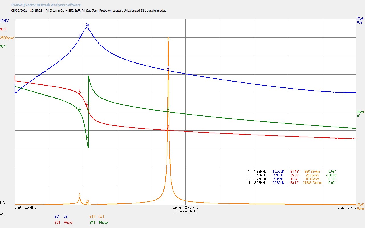
Fig. 1.1 The transmission gain S21 for a cylindrical Tesla coil where the VNWA return probe is connected directly to the top-end of the secondary coil. Loading of the causes the series resonant mode to shift down to 1.45Mc.
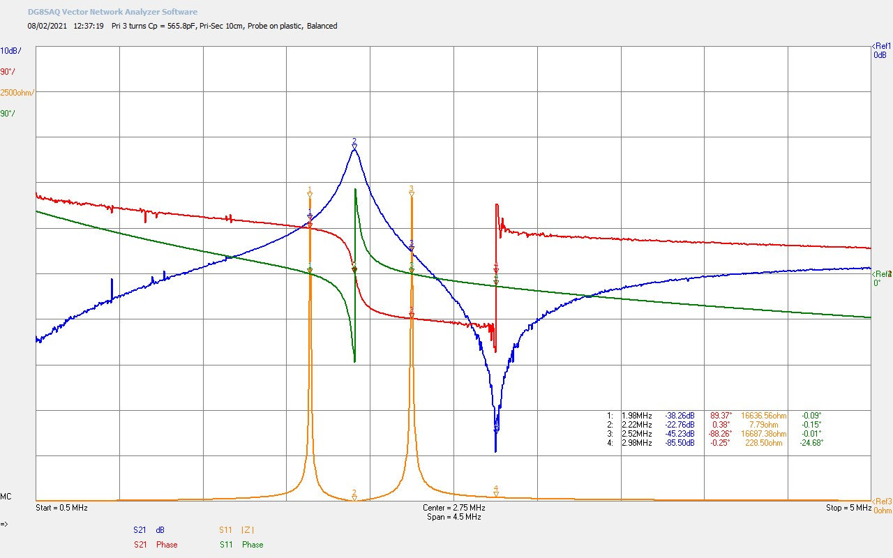
Fig. 1.2 Here the return probe is capacitively coupled to the top-end of the secondary coil by introducing a 5mm space between the two. The coil can freely resonate at its designed freuqnecy of 2.27Mc with a 2m bottom-end wire extension.
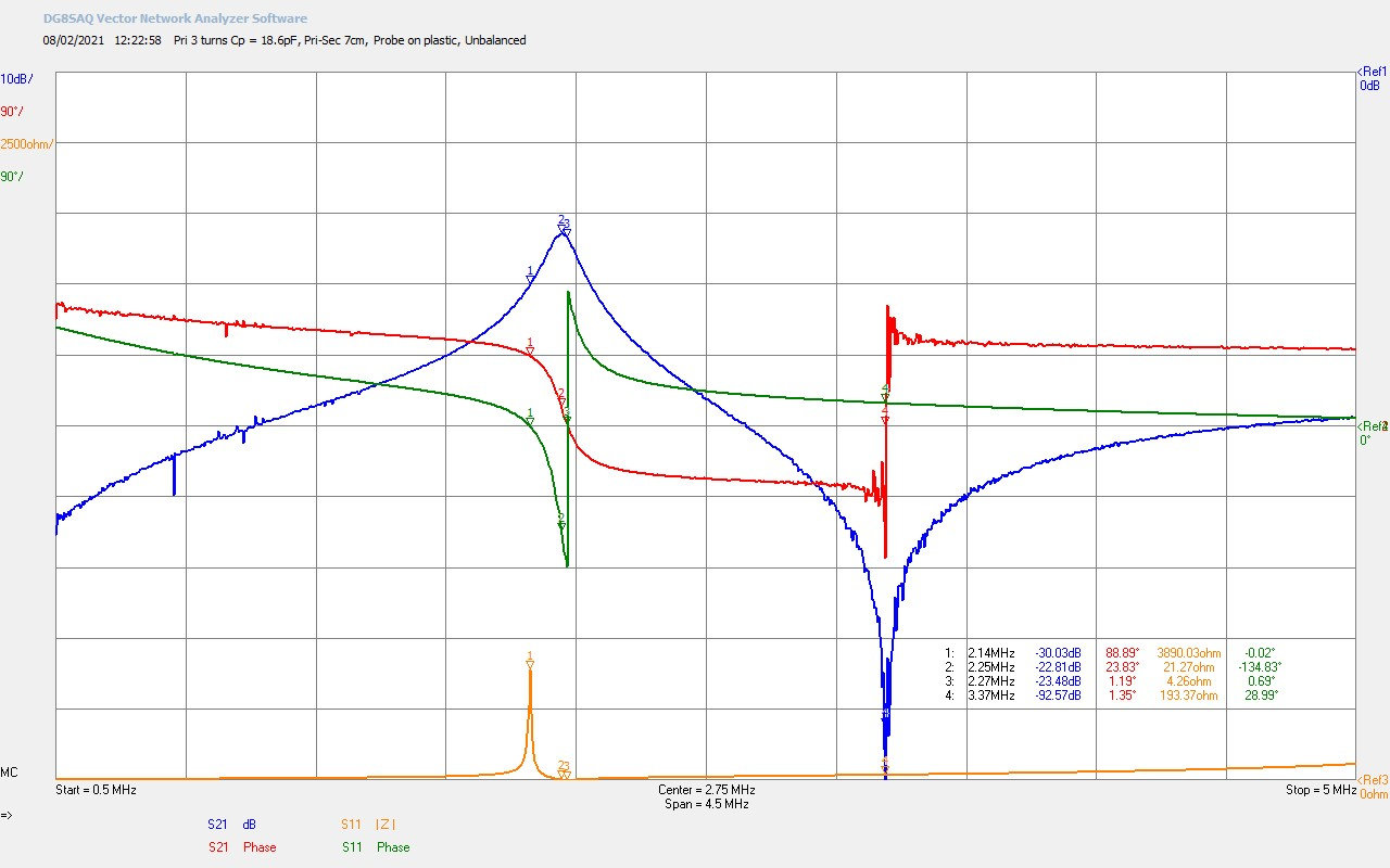
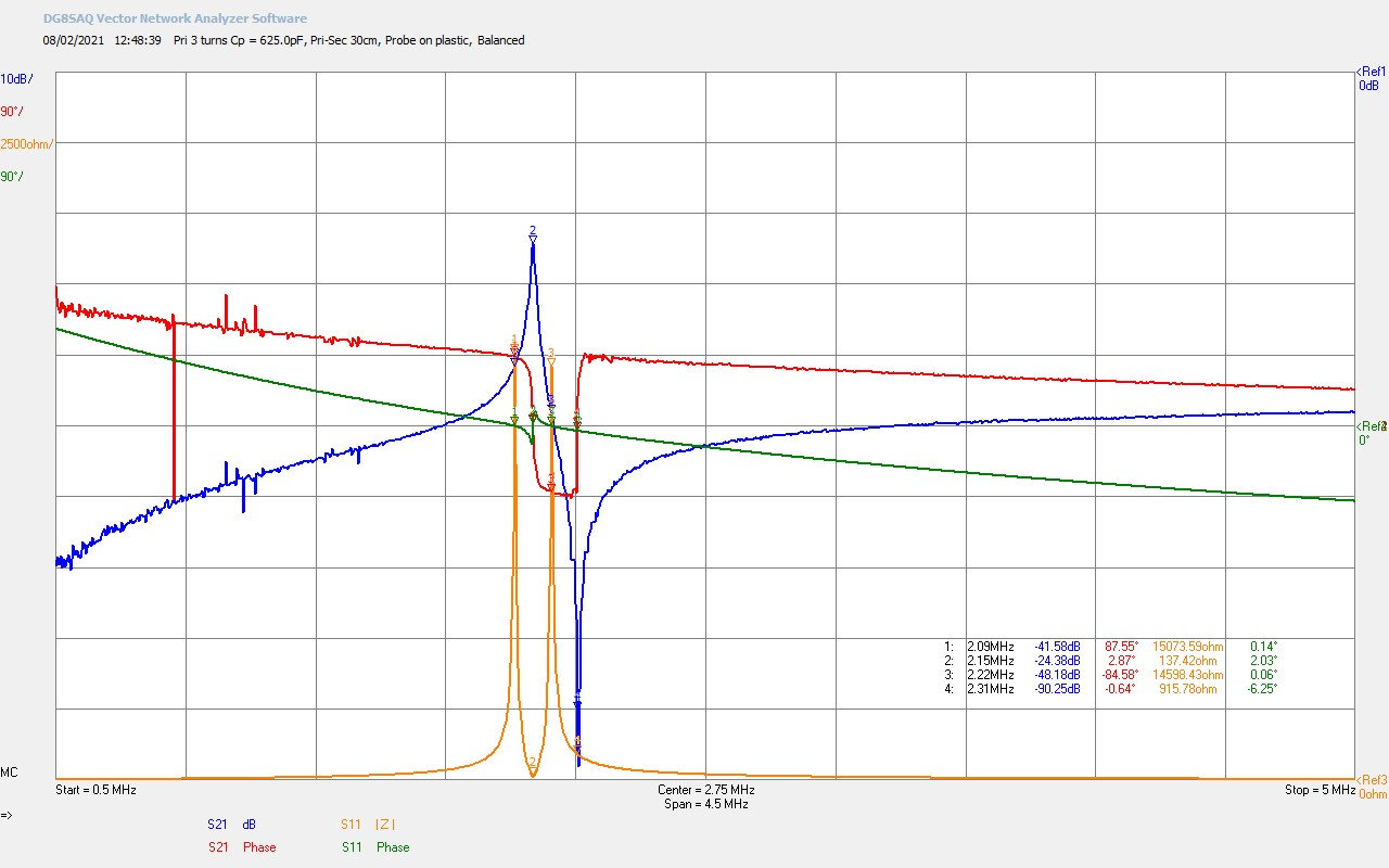
Fig. 1.3 S21 shows both a series mode resonance and a parallel mode resonance. Here the input impedance is unbalanced with a very small primary tuning capacitance of 18.6pF. This cause slight mismatch between the series mode seen in the primary and the secondary.
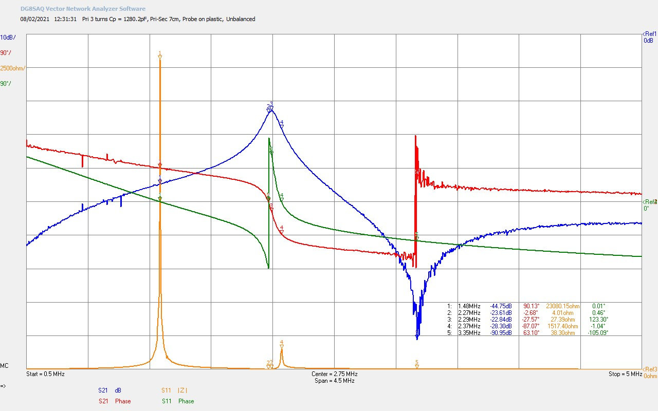
Fig. 1.4 Here the input impedance is unbalanced the other way with the primary tuning capacitor set to maximum at 1280.2pF. Again a slight imbalance is introduced into the series resonant mode observed in S21 and Z11. The parallel mode remains mostly unaffected.
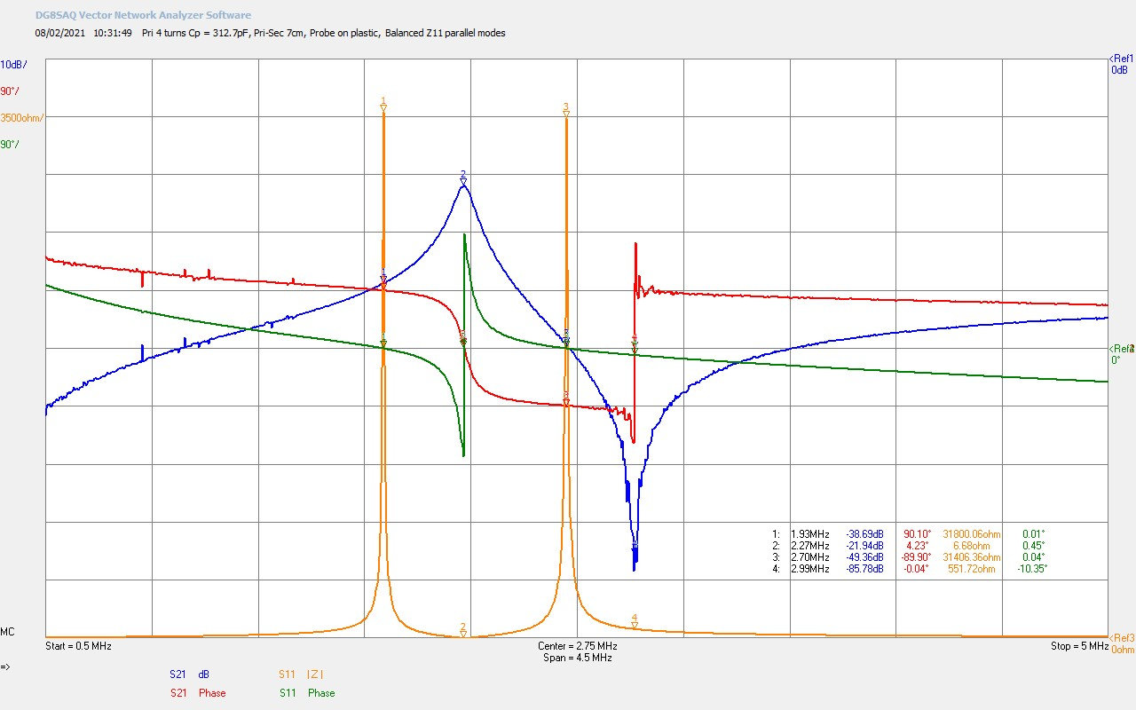
Fig. 1.5 Here Z11 is balanced and the primary turns have been increased from 3 to 4. The insertion loss has been reduced by the increased magnetic induction field coupling, and the parallel mode has been shifted down in frequency.
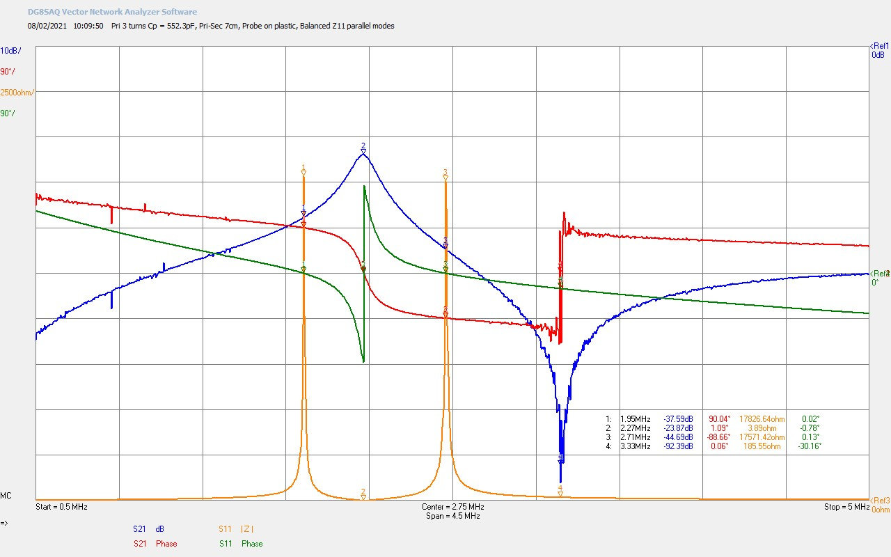
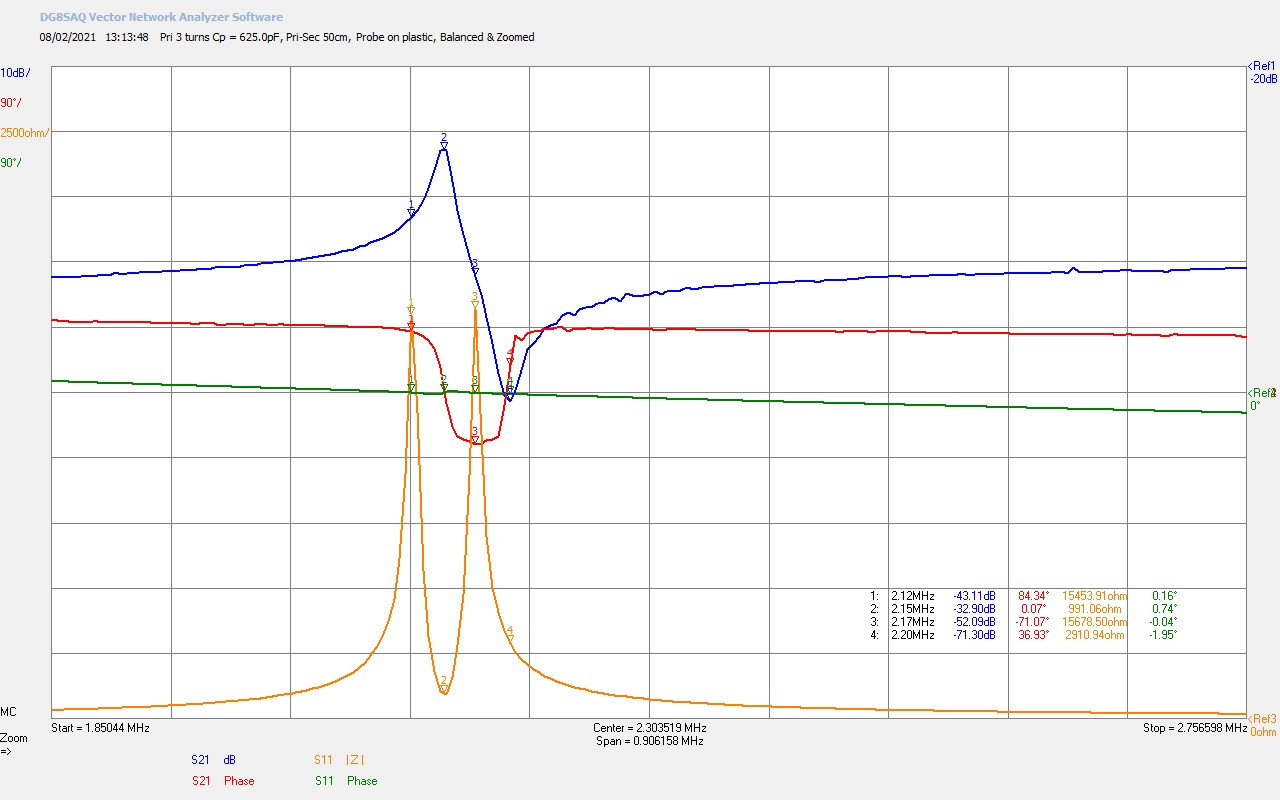
Fig. 1.6 The primary with 3 turns and balanced parallel modes in Z11. The insertion loss when capacitvely coupled at the top-end adds an additional ~20dB, making the total loss ~23.9dB. Series resonant mode frequency stays approximately constant.
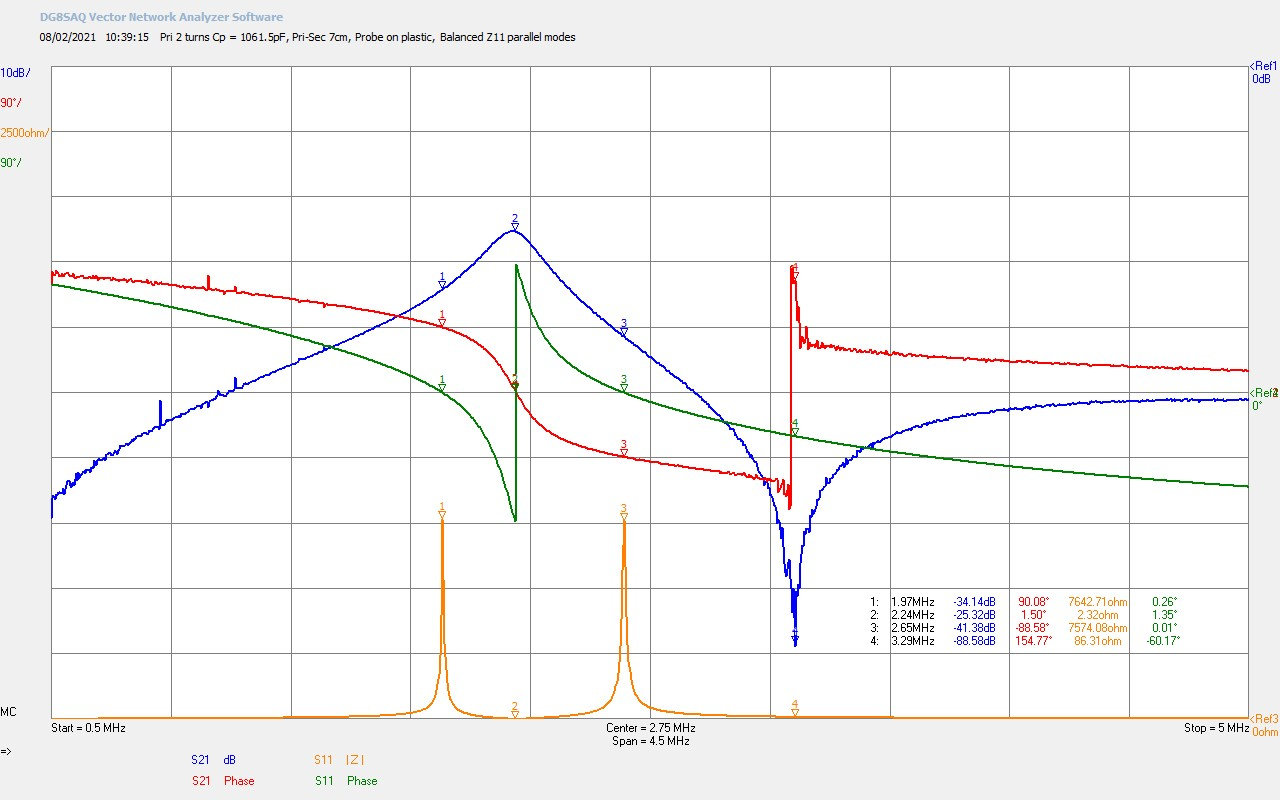
Fig. 1.7 Primary turns reduced to 2 turns, with the corresponding increase in insertion loss in S21. The parallel mode in S21 remains largely unaffected by the reduction in turns.
To view the large images in a new window whilst reading the explanations click on the figure numbers below.
Fig 1.1. Here we see the basic form of the transmission gain S21 when the return probe is connected directly to the top-end final copper turn of the secondary coil. The secondary coil is of course loaded by the 50Ω input impedance of the VNWA which causes the free resonance of the secondary coil, (nominally 1.95Mc in the 160m amateur band with the bottom-end rf grounded, and ~2.25Mc with a 2m wire extension at the bottom-end), to be dramatically reduced in frequency to M2 @ 1.45Mc and with an insertion loss across the complete system of 5dB. Calibration of the VNWA confirmed that insertion loss without the TC was << 0.1 dB.
The form of the transmission gain takes on that typical for a high-Q resonant circuit where at the series fundamental resonant frequency the gain peaks with a quality factor determined by the resistive losses in the system which is dominated here by the series resistance of the secondary coil. From the input impedance characteristics Z11 @ M2 we can see the transformed down series resistance of the secondary coil in the primary RS is 25.8Ω. The phase of the transmission gain around the series resonance at M2 is also typical for the characteristics of the series resonant TC and represents the transition of the secondary from an inductive element to a capacitive element with the corresponding phase shift from +90° to -90°.
In correspondence the characteristics of Z11, here shown in the unbalanced parallel mode condition, shows the fundamental series resonant mode with minimum series resistance in the primary at M3 @ 1.47Mc with RS = 10.4Ω. The correspondence of M2 and M3 is very close here, but not exact. This results from the tuning in the primary which in this case is a very unbalanced condition for the parallel modes in the primary and secondary at M1 and M4. In this case the upper parallel mode at M4 from the primary dominates, which is more than sufficient to skew the characteristics of the secondary coil when coupled to the primary in an unbalanced fashion as demonstrated. In the transmission gain markers at M2 and M3 can be seen to be very close but not exact.
This slight mismatch of the series mode in the primary and secondary would appear to be insignificant, but does lead to interference in the cavity when trying to tune for very high efficiency of transference of electric power in a TMT cavity, and hence instability and loss of selectivity in the tuning process, making it very difficult to sustain the highest efficiency transference of power. Where possible maintaining the parallel modes in optimal balance considerably reduces this instability and facilitates tuning a TMT system to stably transfer high power in a sustained fashion with efficiencies > 99% in the close mid-field region.
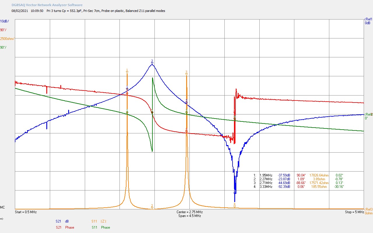
Fig 1.2. Shows the effect of moving the return probe from the top-end of the secondary coil to the closely spaced plastic guard ring, shown on the video above the copper shield turn. Removing the loading from the top-end of the secondary coil allows to freely resonant according to its intrinsic properties, and reveals a most interesting second order effect in the overall properties of a TC. The transmission gain S21 now demonstrates both a transmission peak from the fundamental series resonant mode at M2, and a parallel resonant mode at M4 where the impedance of the secondary effectively becomes very high, and no power is transmitted through the coil, rather being stored in the coil instead at this frequency. This parallel mode can be identified as properly a second resonant mode of the coil based on the sharp phase change occurring at M4. In figures 3, later in this post, we look at a simple equivalent circuit model for the TC resonant circuit that demonstrates how this characteristic of a series and parallel mode may arise.
Before going there if we look in more detail at the measured S21 characteristics. Firstly for the series fundamental resonant mode at M2, the maximum transmission gain has shifted back up to that expected for the coil design in the 160m amateur band and bottom-end connected by a 2m extension wire. This series resonance occurs at 2.27Mc and is the minimum input impedance drive point transformed down into the primary RS = 3.9Ω. This input series resistance in the primary is properly the combination of the resistance presented by the primary circuit and the transformed down series resistance of the secondary coil at resonance. This impedance transformation into the primary is based on the square of the ratio of the secondary to primary coil turns, and then scaled by the magnetic coupling coefficient k. If we assume the series resistance of the primary circuit to be exceedingly low << 0.1Ω, then the measured value for RS of 3.9Ω is entirely from the transformed down secondary coil:
Impedance transformation of the TC based on the turns ratio = (NS/NP)2 = (24/3)2 = 64
Series resistance of the secondary at M2 the fundamental series resonant frequency of 2.27Mc = 3.9Ω x 64 x k ~ 67Ω, (where the magnetic coupling coefficient k was determined empirically to be ~ 0.27).
The insertion loss of this series mode has now increased significantly from 5dB to 23.9dB based on moving the return probe from direct circuit connection to capacitive connection at the top-end of the coil. This capacitive connection of 1-2pF introduces an ~ 20dB loss in the transmitted signal that remains constant throughout the rest of the measurements. Empirically we find that the overall insertion loss of the TC, factoring in the loss from the probe proximity, to not have changed significantly and is of the order of 4-5dB. The capacitive probe coupling is an order of magnitude less than the self-capacitance of the TC system, and hence is not expected to substantially influence the measured form of the S21 and Z11 characteristics over the measured band.
By unloading the top-end of the coil and allowing the secondary to freely resonate we have revealed a most important second order effect that relates to a parallel vibration mode in the secondary coil, conjectured to arise from the distributed inter-turn capacitance from the geometry of the coil, and conjectured to instigate the formation of a longitudinal magneto-dielectric transmission mode (LMD), in the electrical cavity of the secondary coil and its extension. In this case the parallel mode at M4 is at a frequency of 3.33Mc and is a real resistance maximum where energy is not transmitted through the TC, but can be stored or accumulated in the coil, and particularly in a top-load if one where connected at the top-end of the secondary coil.
It should also be noted that the parallel modes measured in the input impedance characteristics Z11 have been balanced by adjustment of the parallel tuning capacitor in the primary CP = 552.3pF. The lower parallel mode is from the secondary at M1 = 1.95Mc, and the upper parallel mode is from the primary M3 = 2.71Mc. It remains to be determined if and how the lower and upper parallel modes measured in the input impedance correlate with the parallel resonance mode in the transmission gain secondary. Some consideration of this will be made in the following measurements looking at the dependence, of the both the series and parallel resonant points in the transmission gain, on configurable parameters of the TC system such as the number of primary turns, and the coupling with distance of the primary and secondary coils.
Fig 1.3. Here the primary tuning capacitor has been adjusted to be fully open at its minimum value of CP = 18.6pF. This significantly unbalances the parallel modes in the input impedance Z11 so that the parallel mode of the secondary is now at M1, and the mode from the primary has now shifted off the top of the measured band >> 5Mc. The series mode in the transmission gain, both in frequency and insertion loss, is only very slightly effected to 2.25Mc and 22.8dB. It should be noted that the large imbalance on the input parallel modes introduces a slight misalignment of the series mode in the input and the series mode in the transmission gain, which can be seen in the difference between markers M2 and M3, a difference of ~ 20kc. Interestingly the parallel mode in the transmission gain also remains reasonably constant at M4 3.37Mc, up from 3.3Mc in the balanced condition, a difference of 40kc.
A linear amplifier oscillator would be best tuned to the series mode at M3 for maximum transference of electric power through the TC or TMT system. Although drive point at M2 has a very slightly lower insertion loss in the transmission gain, the input impedance at this point is significantly more than for M3. At M3 the input impedance is purely resistive and represents the best match to the generator in transferring power from the generator to the primary circuit, whereas the impedance at M2 is higher and has an associated reactance, so not a pure resistive impedance at resonance.
Fig 1.4. Here the primary tuning capacitor has been adjusted to be fully closed at its maximum value of CP = 1280.2pF. This again significantly unbalances the parallel modes in the input impedance Z11 so that the parallel mode from the primary now dominates at M1 1.48Mc, and the parallel mode from the secondary is now pushed to the upper mode and heavily suppressed at M4 2.37Mc. Once again the series and parallel mode transmission gain characteristics are only very slightly affected moving no more than 20kc from the balanced condition. It should be noted that the optimal series primary mode drive point has now shifted down to M2, and away from M3 as per the previous minimum CP tuning in Fig. 1.3. The stable drive point for a series feedback oscillator would now be at M1 1.48Mc.
Overall the last two figures have looked at the impact on the transmission gain of the TC by tuning the primary tuning capacitor through it maximum range. It can be seen from the measurements that whilst this has significant import on the input impedance of the TC system, and hence the optimum drive points for different types of generators, it makes only the smallest difference to the series and parallel resonant modes in the secondary coil. This relative independence between the matching and tuning of the primary and secondary modes of the TC, has been well utilised in the Transference of Electric Power experiments, in order to tune the TEM mode for maximum power transfer from the generator to a TMT cavity, and then for LMD mode tuning in the cavity of the TMT between the two TC endpoints. The overall result when both the TEM and LMD modes are tuned optimally in the complete TMT system, is high-efficiency transference of electric power down a single wire transmission medium in the mid-field region, explored and reported so far in High-Efficiency Transference of Electric Power parts 1 and 2.
Fig 1.5. In the next two figures we look at the changes in the transmission gain characteristics with changing number of turns in the primary. Here the primary windings have been increased from 3 to 4 turns, and the TC has been tuned using the primary tuning capacitor to balance the parallel modes in the input impedance Z11. The effect on the series resonant mode in transmission gain S21 is only slight, with the frequency remaining almost completely constant at M2, 2.27Mc. The increased magnetic coupling from an extra turn has reduced the insertion loss from 23.9dB to 21.9dB at M2. The increased magnetic induction field coupling has also intensified the lower and upper parallel modes in the input impedance shifting the peaks to higher impedance, and hence a vertical axis scale shift from 2500Ω/div to 3500Ω/div. However the most remarkable change is in the parallel resonant mode in S21 which has shifted dramatically down in frequency from 3.33Mc in Fig. 1.2 to 2.99Mc, a shift of 340kc.
From our previous discussion we have so far considered the possibility that this parallel resonant mode in S21, that may originate from the distributed inter-turn capacitance of the secondary, is also strongly affected by the distributed capacitance in the primary as well. This leads me to conjecture that the parallel resonant mode in the transmission gain is influenced by the extension of the dielectric induction field from the primary to the secondary, or a capacitive coupling across the turns of the primary and the secondary coil together. If this were the case it would give a more complete view to the transference of electric power across an entire TMT system, and thus far explored in the research currently presented on my website.
For power to be coupled from the generator and through a TMT system via a single wire or Telluric transmission medium to a distant load, it is necessary for the dielectric and magnetic fields of induction to be transferred from source to load, or to extend, albeit in this case incoherently, across the complete system. Power transfer in this regime through induction in a TC requires both the dielectric field extending across the inter-turn distributed capacitance of the primary and the secondary, whilst the magnetic field is coupled between the primary and the secondary coils. Together both induction fields lead to a balanced and equilibrium circuit condition that requires both the TEM arrangement in the primary of the transmitter and receiver TCs, and the LMD mode in the single wire medium of the cavity between the secondary end-points.
Whilst this is purely a conjecture at this time, and relies both on the LMD transmission mode model, and induction field mechanics in the TC transformers, it does appear to me as an interesting and consistent expression of the balance and cooperation required within the inter-dependent relationship formed between the differentiated induction fields at the level of transference. We will see further in figures 3 how the parallel resonant mode in S21 varies strongly according to the distance between the primary and secondary coils, additionally suggesting dielectric induction field continuity between the two coils in the TC system.
Fig 1.6. Here the number of primary windings have been reduced from 3 to 2 and the input impedance rebalanced. The reduction in the magnetic field induction is clear to see in the transmission gain S21. At the series resonant point at M2 2.24Mc, the insertion loss has now increased from 23.9dB to 25.3dB, and the parallel modes in the input impedance characteristics have been reduced as there is reduced interaction between the parallel mode from the secondary and the parallel mode in the primary, (the vertical scale back to 2500Ω/div, and a reduction in parallel mode peak height from Fig. 1.2). The parallel resonant mode of the secondary has remained relatively constant with Fig. 1.2 only having reduced slightly from 3.33Mc to 3.29Mc.
Figures 2 below build upon what has been explored so far, and looks at the transmission gain S21, and the input impedance Z11, as a function of the distance between the primary and secondary coils, and hence on the dielectric and magnetic induction field coupling and continuity between the two coils.
Fig. 2.1 The transmission gain S21 and input impedance Z11 for a cylindrical coil with a 3 turn primary, and where the primary and secondary coils are separated by an empirically determined optimum distance of 7cm for highest efficiency transference of electric power.
Fig. 2.2 At 10cm there is little change in S21. The parallel modes in Z11 have started to move towards each other as the coupling between the two coils is slightly reduced.
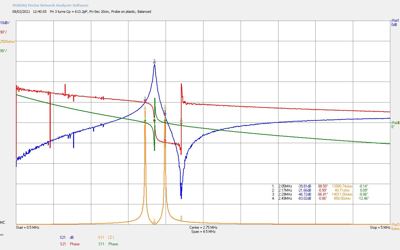
Fig. 2.3 At a coil spacing of 20cm there is more considerable movement of the parallel modes in Z11, and the series and parallel modes in the secondary. All modes are still well defined and with low insertion loss.
Fig. 2.4 At 30cm all modes are still well defined, the insertion loss is starting to increase, and there is a small shift in the fundamental series mode resonant frequency.
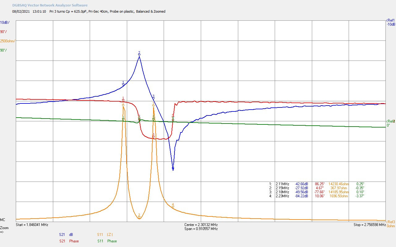
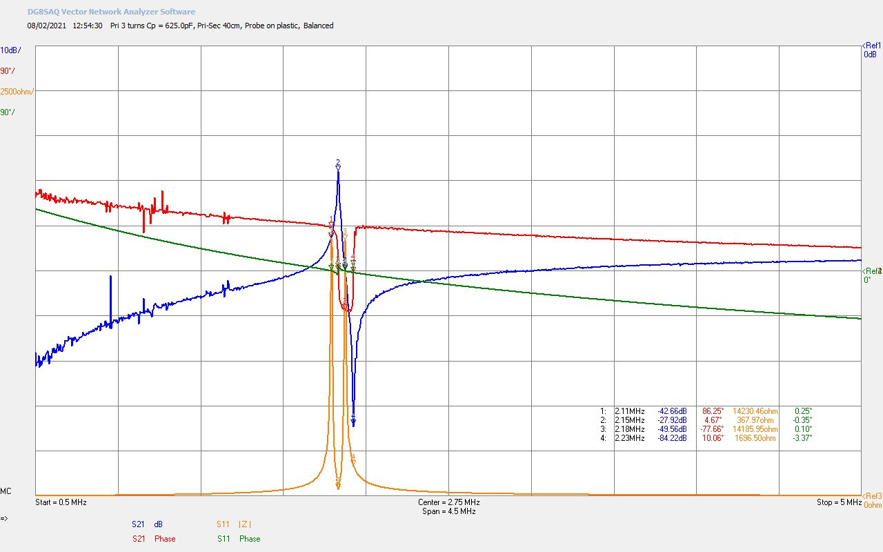
Fig. 2.5 At 40cm all modes are still defined but starting to collapse, as the low coupling between primary and secondary takes the coils further out of each others sphere of influence. The balanced parallel modes of Z11 are collapsing towards a single mode in the primary.
Fig. 2.6 A frequency zoomed view of the characteristics at 40cm, showing all modes defined but progressively reducing as the coil circuits separate.
Fig. 2.7 A frequency zoomed view of the characteristics at 50cm separation. The phase transition of the two coupled circuits is now starting to rapidly collapse, and the parallel mode in the secondary is diminishing.
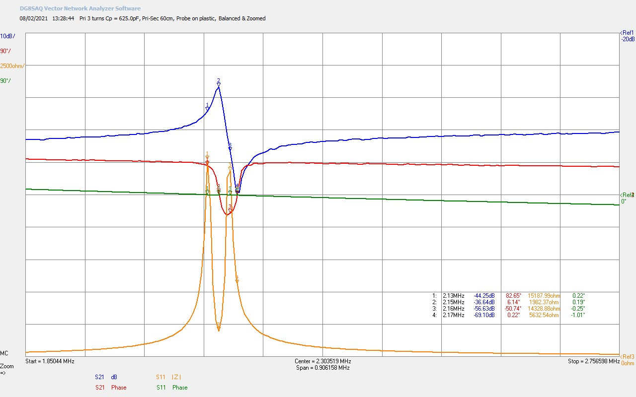
Fig. 2.8 Finally at 60cm the insertion loss has increased over 10dB as the coupling between primary and secondary has become very low. The magnetic coupling coefficient k is < 0.05 here.
Figs 2.1-2.5. The progression of the coil characteristics over the first 5 figures spans a primary to secondary coil distance from 7cm up to 40cm. The two coils that constitute the TC are moved progressively out of proximity with each other reducing the magnetic and dielectric induction field coupling between the two. The transmission gain peak at M2 starts to shift down slightly remaining a relatively constant insertion loss of ~ 22dB before starting to fall-off at separation distances over 30cm. The S21 series and parallel modes start to move closer together with increasing coil situation, and remains in sync with the progressive narrowing of the parallel modes in the input impedance Z11 at M1 and M3. The phase response of the different resonant modes shifts accordingly and remains consistent with the gradual reduction in the induction field influence between the primary and secondary coils.
Overall when the sequence is observed it is clear to see that increasing the distance between the two coils is reducing the inter-action between the two, gradually separating them from a coupled coil system, to two independent coils with defined individual characteristics. It is interesting to note that the collapse of the coupled coil characteristics reflect changes that can be attributed to both the magnetic and dielectric induction fields. In the Z11 characteristics the two upper and lower parallel modes are gradually moving together in frequency, showing the reduced interaction between two modes at the same frequency, the upper from the primary at M3, and the lower from the secondary at M1. In accordance the series and parallel modes reflected in S21 are also proportionately moving together. The peak in S21 from the fundamental series resonant mode at M2, and the parallel mode at M4.
Figs 2.6-2.8. Show the final stages of collapse of the coupled coil characteristics as the distance between the two coils moves from 40cm to 60cm. Here the frequency axis has been zoomed to span only ~ 900kc, so that the details of the collapsing characteristics can be observed clearly. By 100cm the two coils are fully outside their field of influence, and the coupling of the induction fields between the two coils is insignificant, and the electrical properties of each are entirely dominated by the characteristics of the individual coil, and not by their inter-action. Any attempt to tune or adjust each individual circuit has no effect on the properties of the other. This may seem obvious since there is no-longer any coupling between the two coils, but the extent of the induction field influence is surprising at almost 1m between them, and suggests that the magnetic and dielectric fields of induction have a combined sphere of influence on the electronic properties of electrical elements, that can extend further than either of the induction fields individually.
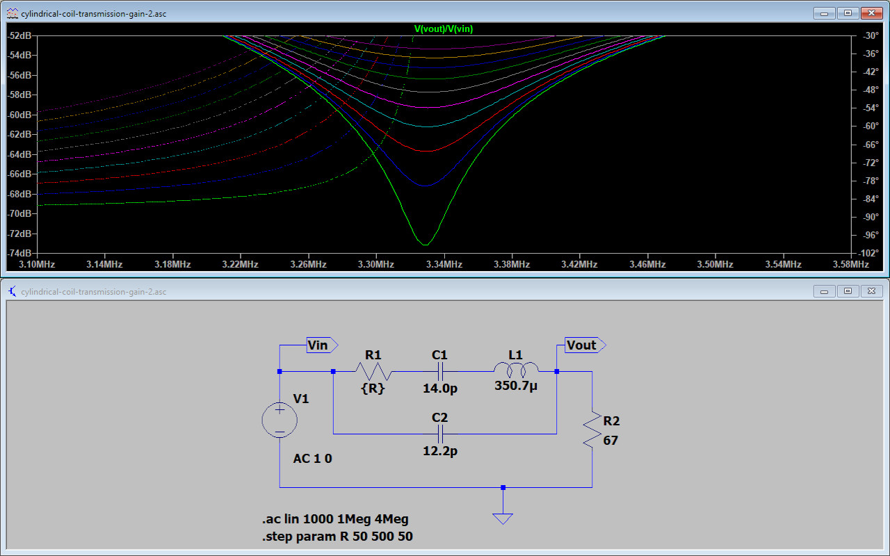
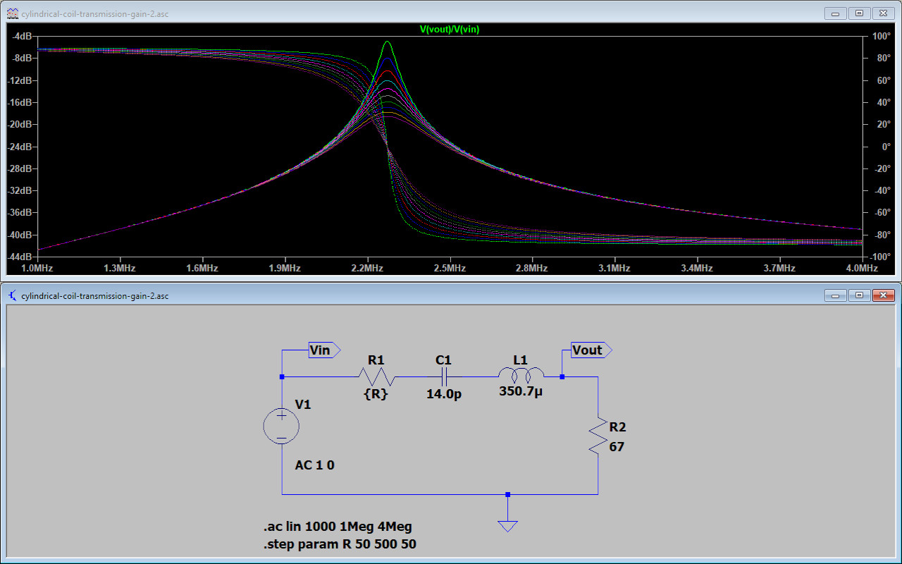
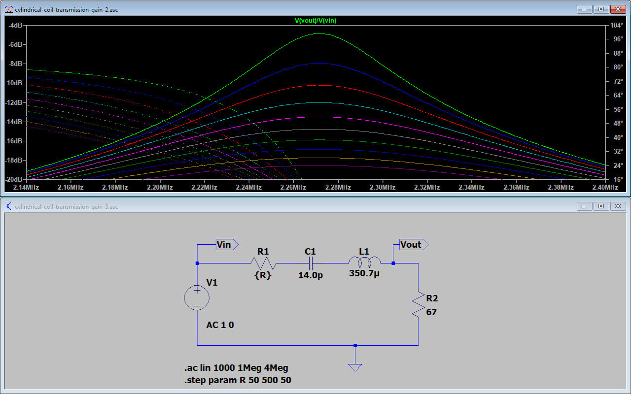
Figures 3 below consider a simple equivalent circuit of the TC system modelled in LTSpice. The results of the modelling show the voltage transfer gain of the equivalent circuit over the frequency range 1 – 4 Mc. The modelled equivalent circuit reveals surprisingly close correspondence, for such a simple model, to the key features of both the series and parallel modes in the measured transmission gain S21, and especially using the actual measured and derived lumped element circuit values from the cylindrical TC.
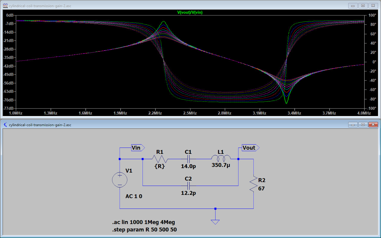
Fig. 3.1 An LTSpice modelled simple lumped element equivalent circuit for the cylindrical Tesla coil. The model uses actual measured and derived values to obtain a good fit at both the series and parallel resonant modes.
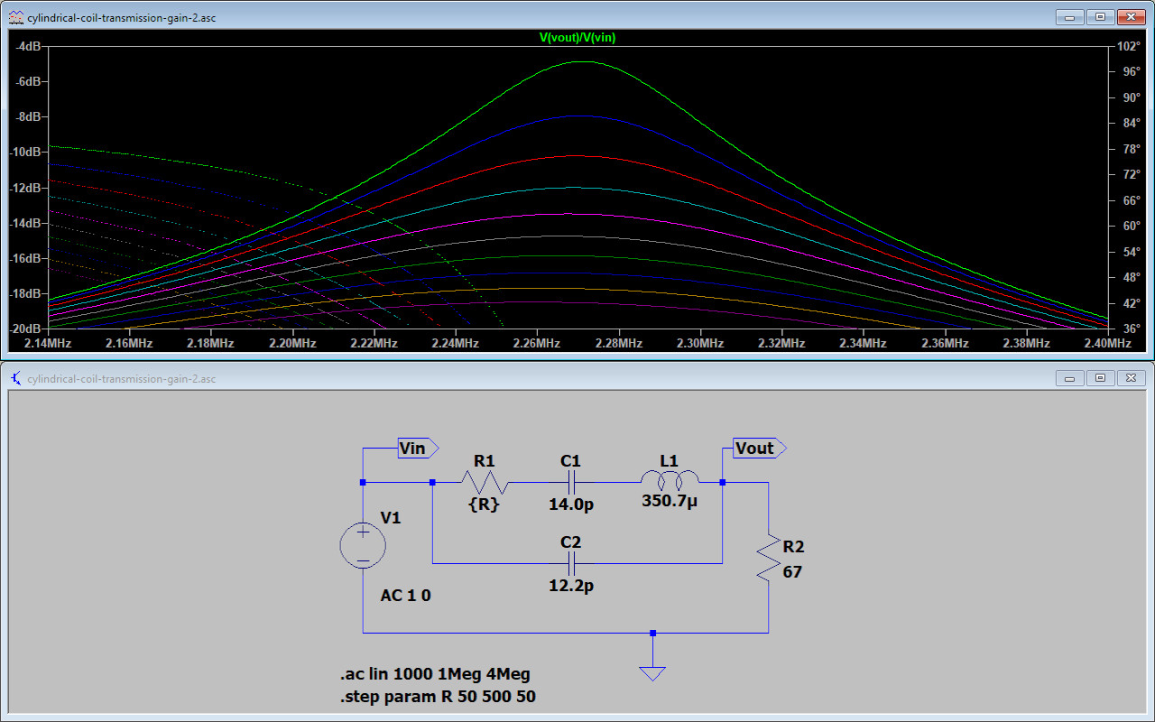
Fig. 3.2 A frequency zoom of the transfer gain showing the fundamental series resonant mode at 2.27Mc, and with an insertion loss of ~ 5dB. The varying series resistance R1 shows the impact of loss on insertion loss and quality factor Q.
Fig. 3.3 A frequency zoomed result showing the parallel resonant mode in the transfer characteristics at 3.33Mc and insertion loss of ~ 73dB. Again the varied series resistance shows the impact of the loss on the Q of the parallel mode.
Fig. 3.4 When the element C2 representing the inter-turn distributed capacitance is removed the parallel mode no longer appears in the transfer characteristics. All other elements remain the same, and the series resonant mode is unaffected.
Fig. 3.5 A frequency zoomed view of the transfer characteristics of the series resonant mode, without the element C2 in the model. The series mode remains at 2.27Mc and with an insertion loss of ~ 5dB.
The equivalent circuit consist of the following circuit elements:
L1 – The measured lumped element inductance of the secondary coil 350.7µH.
C1 – The total self-capacitance of the secondary coil derived from the fundamental series resonant mode at 2.27Mc, 14.0pF.
R1 – The series resistance of the secondary coil varied by the LTSpice model from 50Ω to 500Ω in steps of 50Ω to illustrate the effect of changing resistive losses on the transmission gain insertion loss, and quality factor Q of the resonant modes.
C2 – An element to represent the distributed inter-turn capacitance of the secondary coil, and including the conjectured extension of the dielectric field of induction across from the primary coil to the secondary coil. 12.2pF was required to model the parallel resonant mode to 3.33Mc, matching the measured parallel mode in the transmission gain S21 results.
R2 – The transformed up primary circuit resistance into the secondary, based on the TC turns ratio 24:3 and the measured magnetic coupling coefficient k ~ 0.27, R2 = 67Ω. This previously derived element value results in an insertion loss of ~ 5dB at the series resonant mode @ 2.27Mc. This matches very closely the insertion loss measured at this point in the S21 results.
Fig 3.1. Here the overall modelled characteristic can be easily recognised as most similar to the measured transmission gain S21 presented throughout this experimental post. The series resonant mode forms a transfer maximum at 2.27Mc and with an insertion loss ~ 5dB. The parallel resonant mode forms a transfer minimum at 3.33Mc and with an insertion loss ~ 73dB. The phase relation switches the model from inductive to capacitive at the series point, and then back to inductive again at the parallel mode. The phase relationship of the transfer gain moves through the complete ±90°. The variation of the series resistance of the secondary coil shows the changes in quality factor Q of the resonant circuit, and collapsing resonant modes with increased resistive losses. For such a simple equivalent model the match with the measured transmission gain S21 is good, and gives some insight into the nature and mechanisms of the Tesla coil under these conditions.
Fig 3.2. A zoomed view of the series resonant mode reaching a maximum at 2.27Mc, ~5dB insertion loss.
Fig 3.3. A zoomed view of the parallel resonant mode reaching a minimum at 3.33Mc, ~73dB insertion loss.
Fig 3.4. Here C2 has been removed, all other aspects of the equivalent circuit remain the same. This illustrates the effect on the transfer gain by removing the element for the distributed inter-turn capacitance, or that which is conjectured to form the parallel resonant mode, and which has most contribution to the formation of the LMD mode within the cavity of the secondary coil. The results show that the parallel mode is no-longer present, and this element is required to form the parallel mode characteristics in the coil. This suggests that the dielectric induction field is no-longer coupled across the windings of the coil, including across the windings from the primary coil to the secondary coil. The series mode resonance is not affected by this change showing how the parallel and series resonant modes, whilst stemming from the same coil geometry, have a relative degree of independence in the results, something that has also been noted in the experimental tuning and matching of the TEM and LMD modes for high-efficiency transference of electric power.
Fig 3.5. A zoomed view of the series resonant mode reaching a maximum at 2.27Mc, ~5dB insertion loss.
Overall the simple equivalent lumped element model shows interesting correspondence with the actual measured transmission gain, and helps to suggest and confirm the possible mechanisms involved in the formation of the series and parallel modes in a TC system. This model could obviously be developed to a much higher order, and it would be interesting to explore the modelled results for a complete TMT system, involving two matched resonant circuits, corresponding series and parallel mode splitting, and also the required elements necessary to represent the single wire transmission medium, if this is indeed possible in a linear Spice type model.
Summary of the results and conclusions so far
We have experimentally explored the transmission gain S21 for a cylindrical Tesla coil, compared and contrasted the results to Z11 (from S11) the input impedance of the TC, and found that the series and parallel resonant modes are both present within the system in both sets of measurements. A simple equivalent circuit model appears to support the understanding of how the series and parallel modes form, and their relative inter-action and inter-dependence or otherwise to each other. We have conjectured that the dielectric induction field is coupled across inter-turns of the primary and secondary coils, as well as between the primary and the secondary coil, and that indeed the complete picture of the Tesla coil requires both magnetic and dielectric induction to yield the fascinating and unusual phenomena demonstrated by TC and TMT systems.
When viewed as a whole system together both from S11 and S21 the TC is an induction transformer that extends both the magnetic and dielectric fields of induction from the primary to secondary. This is a most important point of consideration because it suggests that the very highest efficiency in the transference of electric power can be accomplished where the induction fields are in equilibrium and balance across the entire electrical system. If it is a TMT system that we are considering, then the highest efficiencies of transference take place when balance and equilibrium are established (tuned) for both the magnetic and dielectric fields of induction, extending all the way from the generator to the load, and both in the TEM mode in the two sections of the system, and in the LMD mode in the single wire and cavity sections of the system. The correct balancing and tuning of both modes allows maximum power to be transferred between source and load.
The analogy is to consider the TMT system as a tubular waveguide, or a pipe, between the source and load. In carefully balanced equilibrium the dielectric and magnetic fields of induction can propagate through the waveguide without experiencing discontinuous and abrupt changes in impedance of the waveguide, (the waveguide is not narrowing or widening along its length). In the LMD transmission model, the mode of transmission is being transformed from the TEM case to the LMD case, and where the waveguide transforms from a twin wire guide to a single wire guide. In the twin wire section the induction fields are in temporal phase but not spatial phase, where as in the single wire case the induction fields are in spatial phase, but not temporal. This phase temporal and spatial reversal and realignment between the mode transformations is for me the key to obtaining the highest transference of electric power in the TMT system.
Ultimately the case could be considered where the dielectric and magnetic fields of induction are coherent both spatially and temporally across the entire TMT system, from source to load through a balanced waveguide. This would lead to a coherent induction field condition where the magnetic and dielectric fields of induction are differentiated but coherent with each other, a condition for me that belongs to the principle of Displacement. Currently the most established macroscopic demonstration of this principle occurs in the field of superconductivity, where the magnetic and dielectric induction fields are differentiated but coherent across the material system, due to cooperation between the electronic and mechanical properties of the material. I conjecture that the inner workings of electricity are completely permeated with this coherent state of Displacement, both as a principle and a mechanism, of inclusive and coherent electric inter-action.
Of course this coherent state probably goes far beyond the basic electric properties of a system, but could be conjectured to be the next inner layer of the hidden, and underlying fabric of nature. Often referred to in the New Science or Alternative Energy fields as the “aether” or “aetheric field”, an amorphous energetic “field”, that is seemingly just outside material manifestation. It is claimed by some that this energetic field can be tapped through the correct principles and mechanisms applied to our experimental apparatus, and called-forth under specific conditions of coherence and particularly through non-linear events; the result of such conditions include, energy injection, and coherent phenomena that result in regenerative action, over-unity gain, and macroscopic coherence over vast spatial distance.
My own research work looks to progressively reveal the inner-workings of nature and these coherent phenomena, through exploring the principle of Displacement and Transference in electrical systems. This work proceeds through the inclusive union of high quality scientific experimentation, impeccable measurement, and considered conjecture in the outer world, and the inner quest for knowledge about my-Self, the hidden underlying wheelwork of nature, and our part within the great mystery of life.
Click here to continue to the next part of cylindrical coil measurements, looking at Cylindrical 3-Coil Input Impedance – Tesla’s Extra Coil.
1. A & P Electronic Media, AMInnovations by Adrian Marsh, 2019, EMediaPress
2. Dollard, E. and Energetic Forum Members, Energetic Forum, 2008 onwards.