


Later in the research, (and after the replica diathermy unit had been designed and built), I was lucky enough to come across a real 1920s H.G. Fischer diathermy unit (HGF), which although being sold untested, and in unknown condition, looked suprisingly good from the pictures. It survived the shipping from the USA to the UK all in one piece, and on closer inspection proved to be in good physical and working condition, including the thermo-ammeter, and the original fuse. The only part missing was the 6V power indicator bulb.
The unit is an early model GP, which is actually a model G in a compact portable cabinet, with a robust carry handle, and metal cabinet corner protectors. Being from the USA the ac line voltage input is specified at 110V 60Hz with a maximum power input of 500W. In the UK this line voltage requires a step-down transformer, a suitable auto-adjusting 1kW transformer was found to be adequate for long-term operation. This post presents detailed pictures, measurements, and an analysis of the HGF as a spark gap generator, and a comparison to the replica diathermy already built and reported in the Spark Gap Generator Part 1 and Part 2.
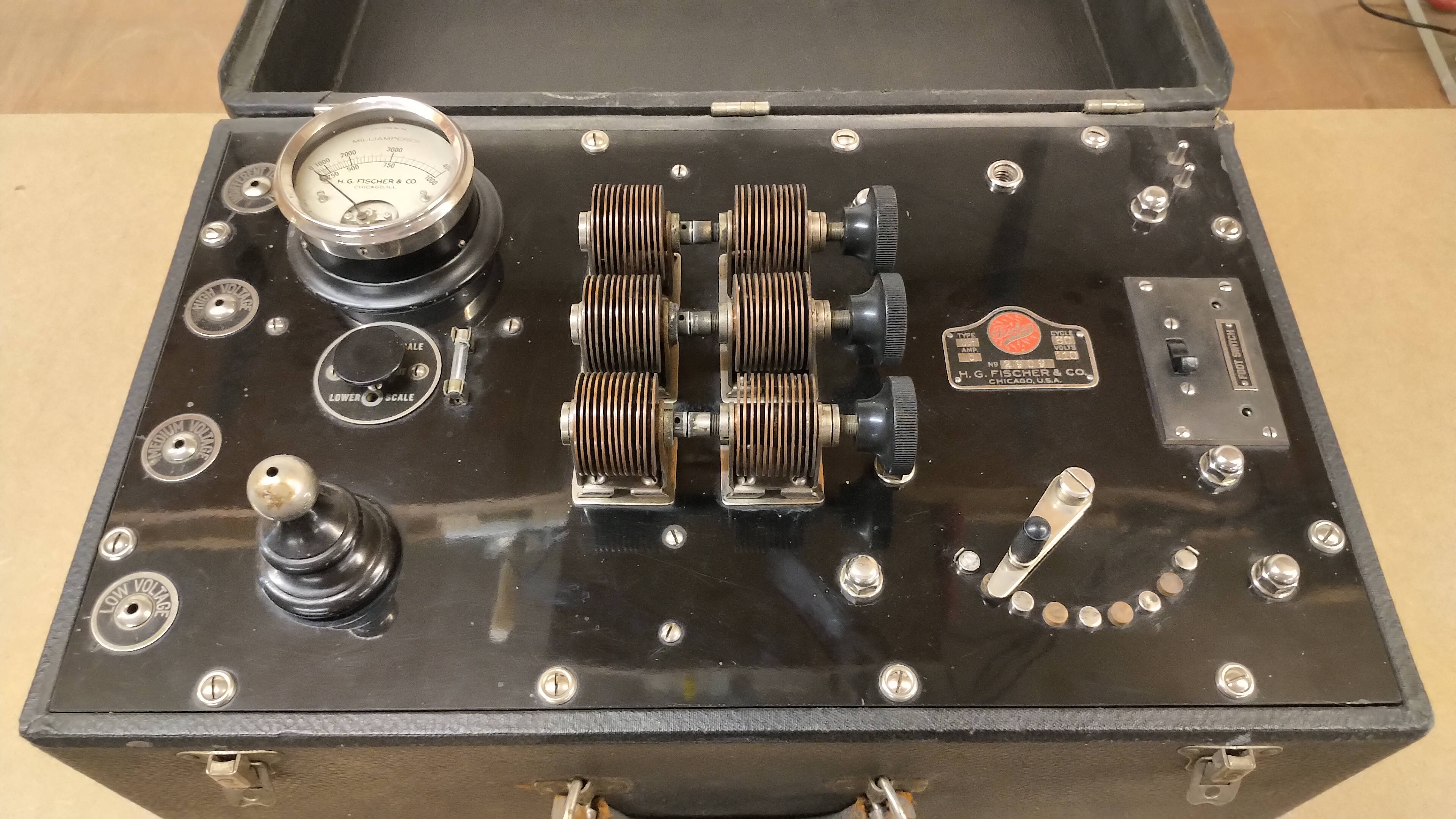
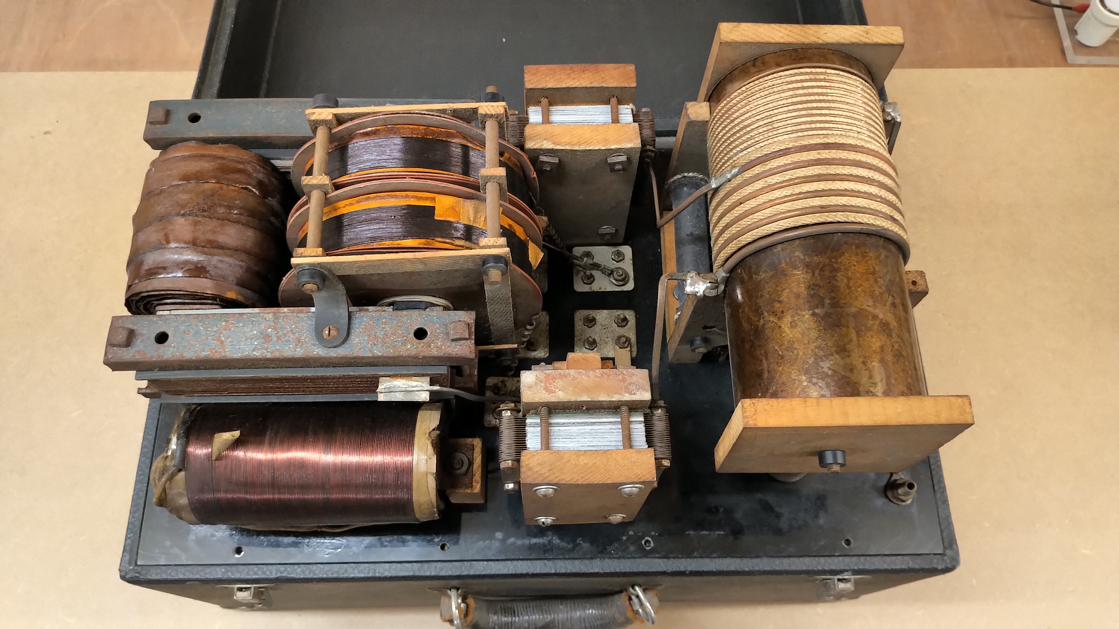
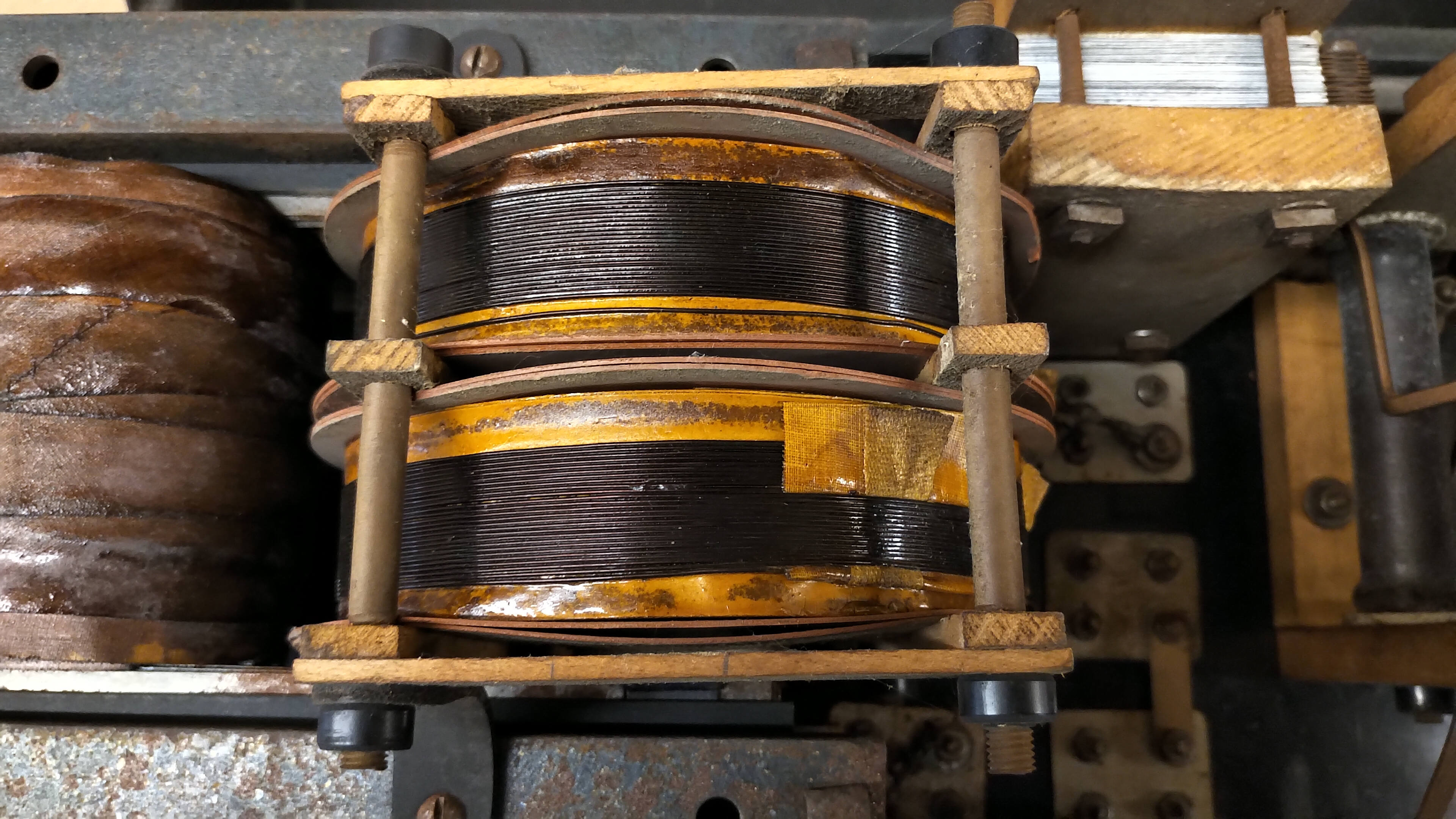
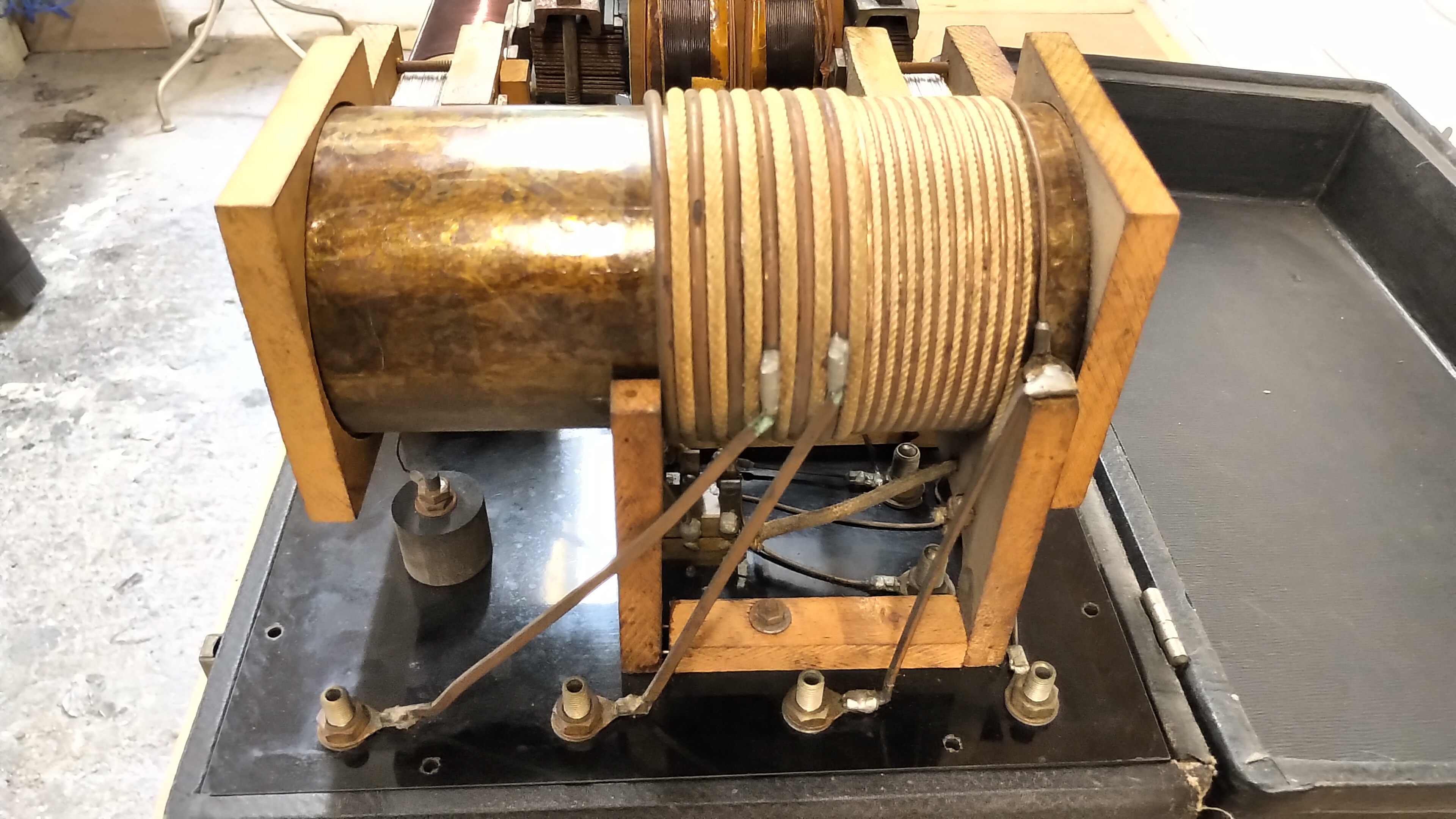
Figures 1 below show the front-panel of the unit, and in detail, the construction and configuration of the various inner components of the HGF:


The actual circuit diagram for the HGF, which was obtained by opening and measuring the unit, is shown in figure 2 below, or click here to view the high-resolution version. Click on the following link to view the original circuit diagram which appears the closest match to this unit model, and comes from the original Model G2.
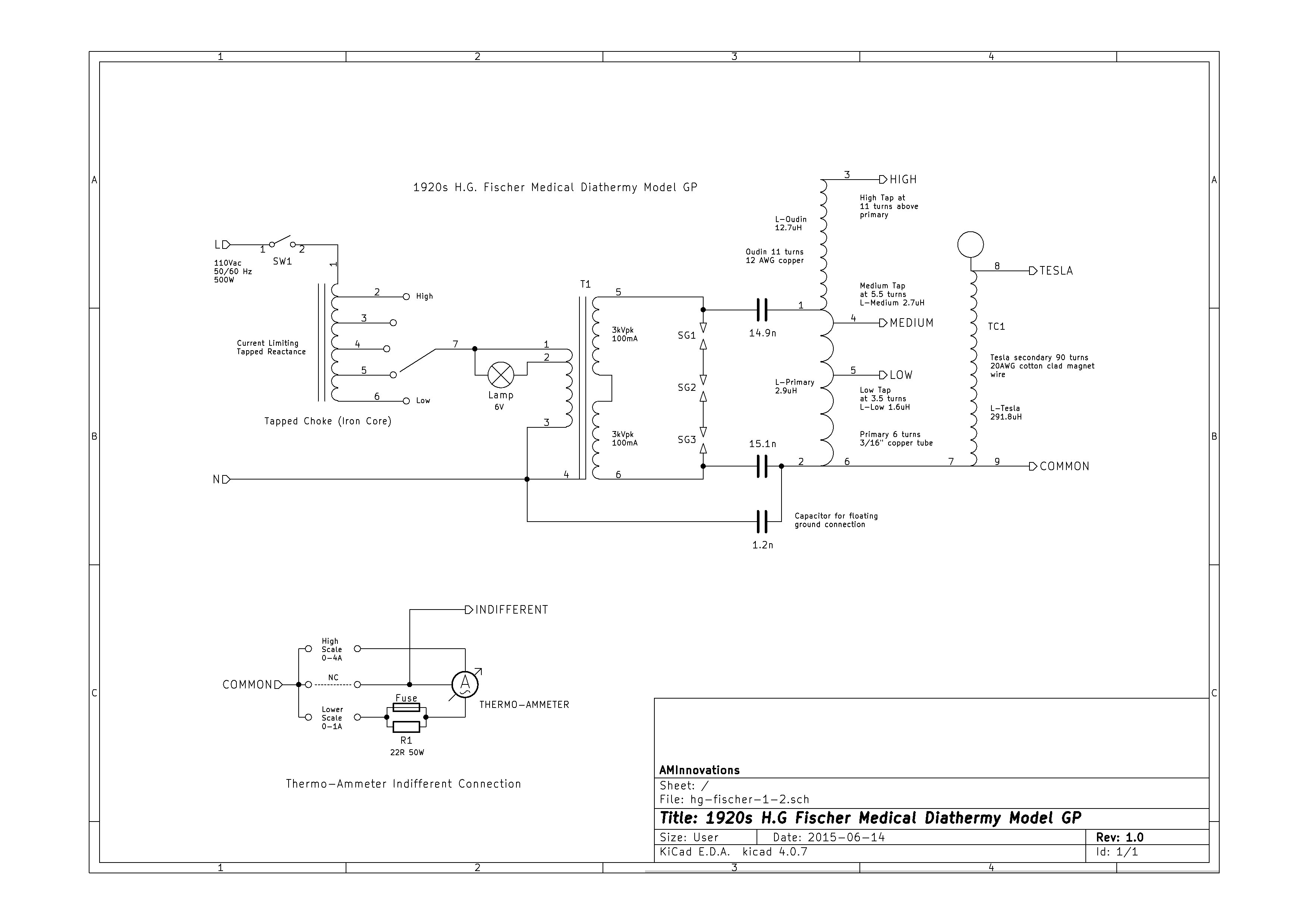

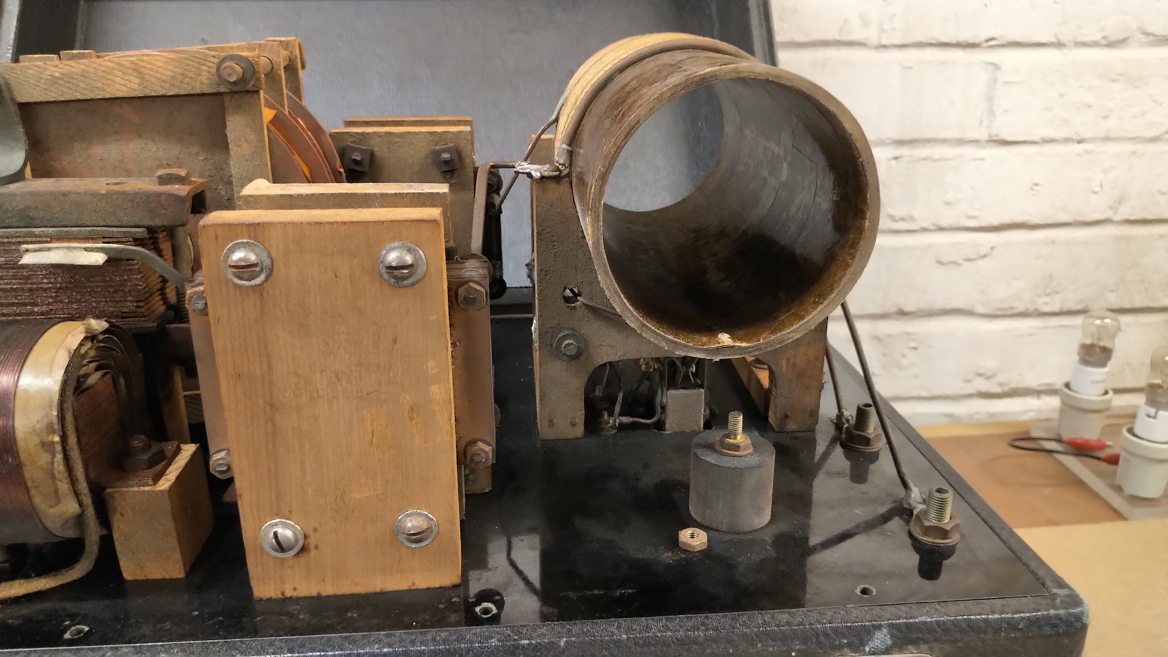
The line input is connected through a switch, (also with outputs for a foot switch), to the input of a multi-tap choke. The choke is designed to restrict the current, based on the output tap setting, through the primary of the high voltage transformer, and hence control the output voltage of the transformer and the strength of the spark discharge. The model G has 5 power settings which control the input power measured in the range 75 – 440W @ 120V, (line output of the auto-adjust step-down transformer). The choke is constructed from multiple layers of windings using AWG 18 solid magnet wire, wound over thin cardboard layer separators, and coated in a Shellac type resin to hold all the windings together. The core of the choke is made from many thin mild steel laminations and mounted each end to the front panel by wooden spacer blocks.
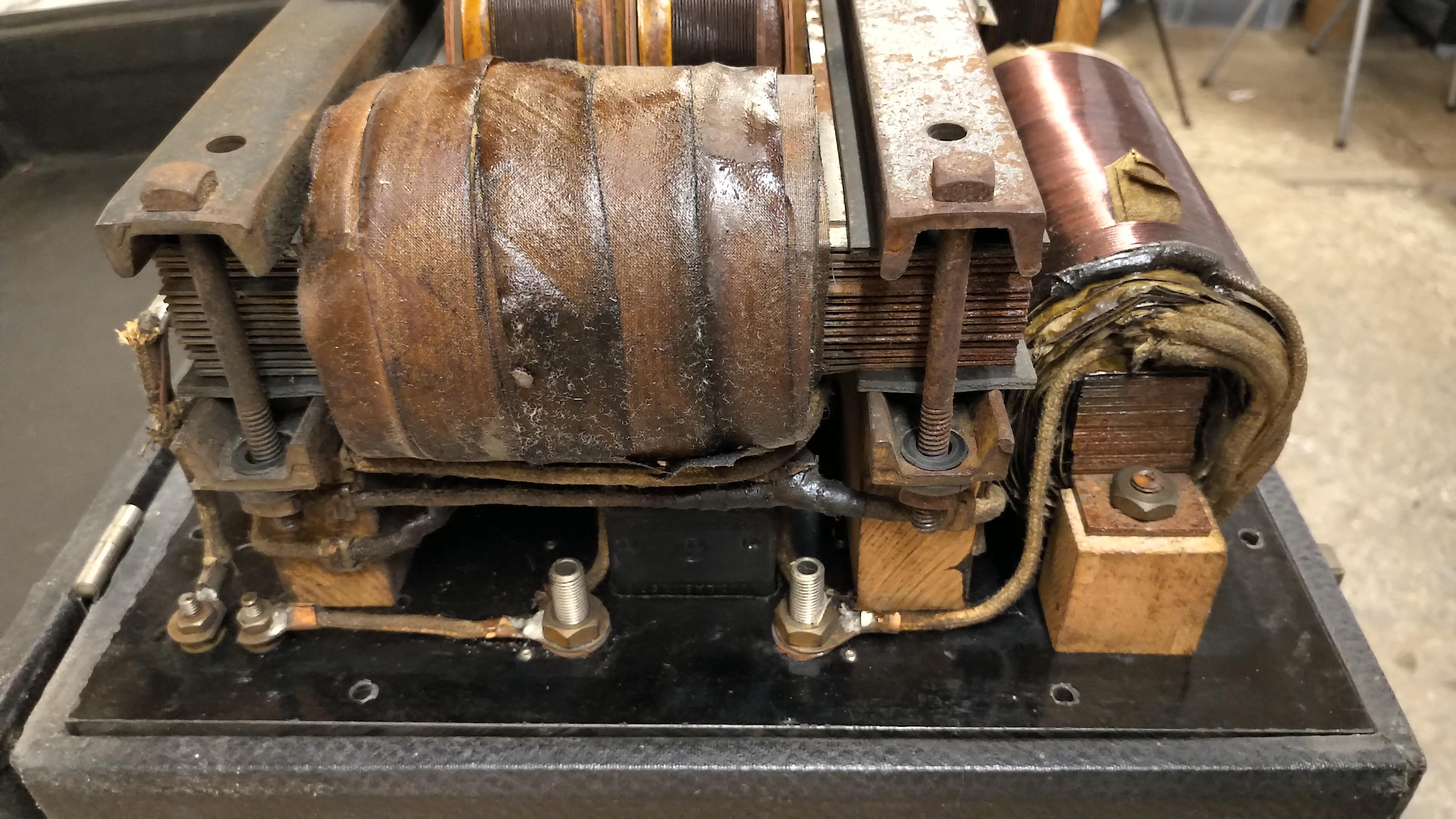
The output of the tap selector from the choke is connected to the primary of the high voltage transformer. The primary is mounted on thicker mild steel laminated core that is rectangular in shape, with the primary at one end, and the two secondary coils at the other. The primary is wound again like the choke with multiple layers of, cardboard separated, AWG 16 solid magnet wire, held in place with the same resin, and then externally coated with paper tape. The two secondary coils are again made from many cardboard separated layers, with ~25 windings per layer of AWG 22 solid magnet wire, and structurally held together by thin wooden layers compressed by insulating fibre threaded rod, and plastic threaded round nuts.
The combination of the primary and secondary coils on the laminated steel core forms an early transformer arrangement. The efficiency of this type of basic transformer is not as high as would be expected for a typical modern design, constructed with modern materials. Increased losses in the laminated core and materials lead to more power dissipation and heating during running, although the size and bulk of the construction results in a robust transformer, that can be run all day long at maximum power without overheating. This is further evidenced that the transformer is still functioning correctly, and is not far short of 100 years old!
The two high voltage transformers are connected in series, and with the outer ends of the two coils connected to the outer ends of the 3 series connected spark gaps, via coiled cotton-clad stranded wire. The spark gaps appear to be a tungsten tipped centre electrode, clad with a machined copper heat sink fin. The other end of the centre electrode is very fine threaded, and with a bakelite adjustment handle at one end to fine adjust the gap spacing of each electrode pair. The outer ends of the 3 series connected spark gaps are connected both to the output of the secondary coils, and the inputs to the series capacitors, in the first stage of a typical Tesla[1] “hairpin” arrangement. Further detail regarding the Tesla “hairpin” circuit and its history is given in a summary presented by Kraakman[2].
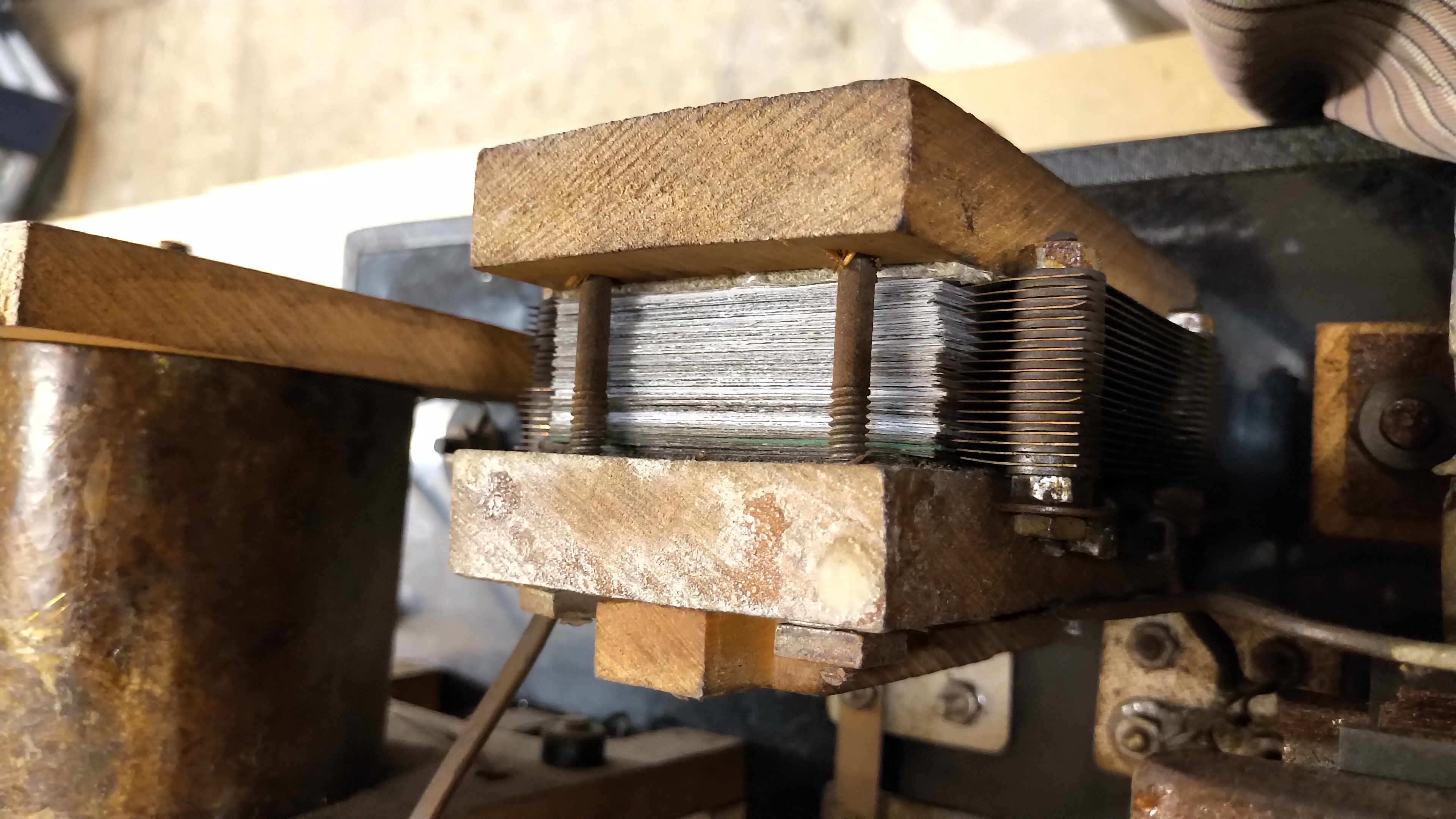
The two series tank capacitors, ~15nF each, are constructed from alternating thin copper conducting sheets with thin insulating mica sheets. These are sandwiched together between two cotton webbed sheets, insulating them from the outer wooden blocks that compress the capacitor sheets together. The wooden end blocks are compressed together by insulating fibre threaded rod, and plastic threaded round nuts. In fig. 1.6 it is important to note that on the left hand tank capacitor there is another smaller capacitor formed on the outside of the wooden block. This is the floating ground connection capacitor important for diathermy use when connected to a patient. This capacitor prevents the final outputs of the diathermy unit to accumulate to very high potentials relative to ground, which would present a considerable discharge danger to the patient from their body to ground. It is somewhat disconcerting to imagine that the safety of the patient, when connected to this type of high tension generator, was only really ensured by the two series tank capacitors and the floating ground connection capacitor. Failure of any one of these three capacitors would effectively connect the patient to around 6kV @ 100mA at the input line frequency of 50/60Hz!
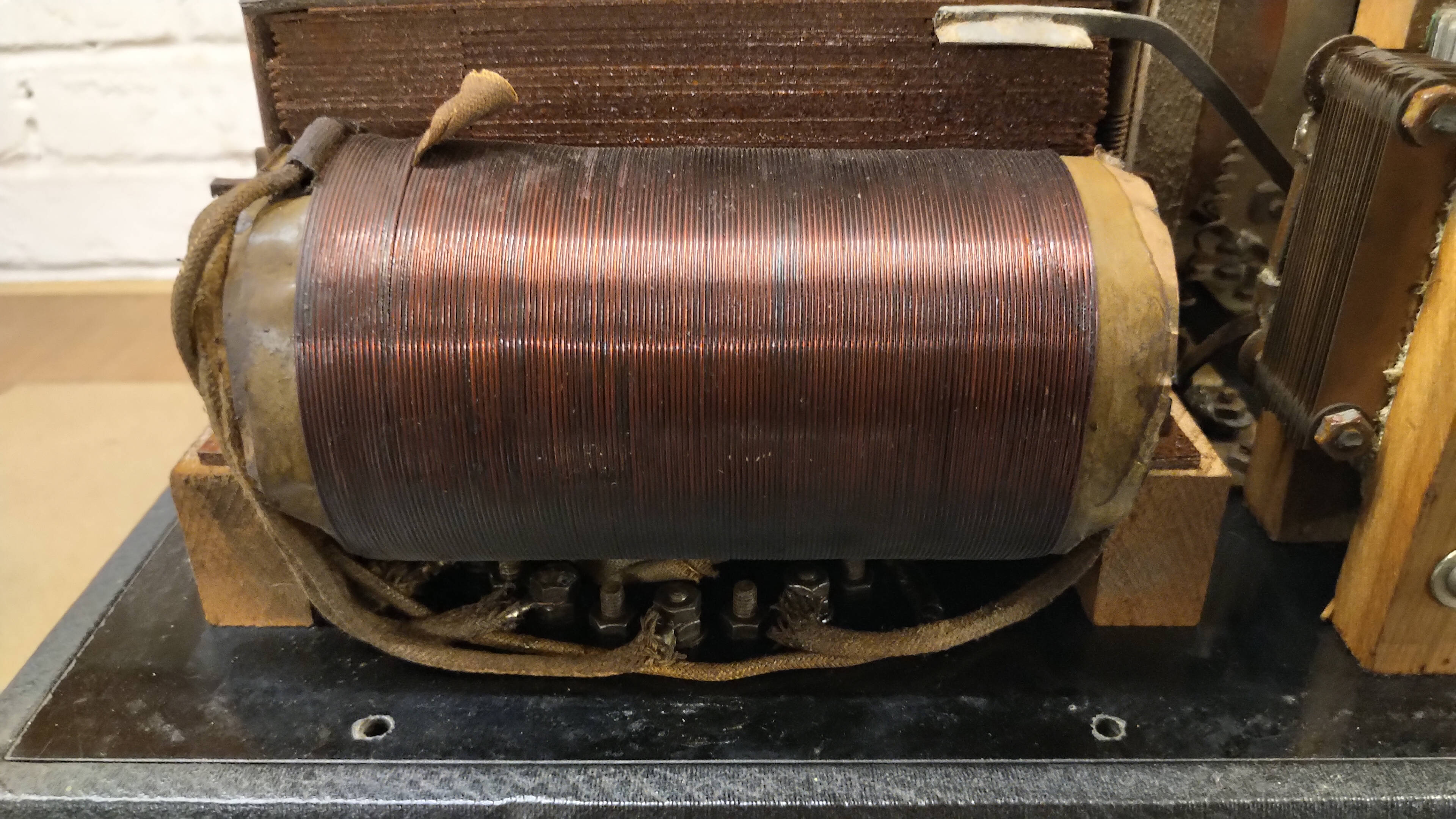
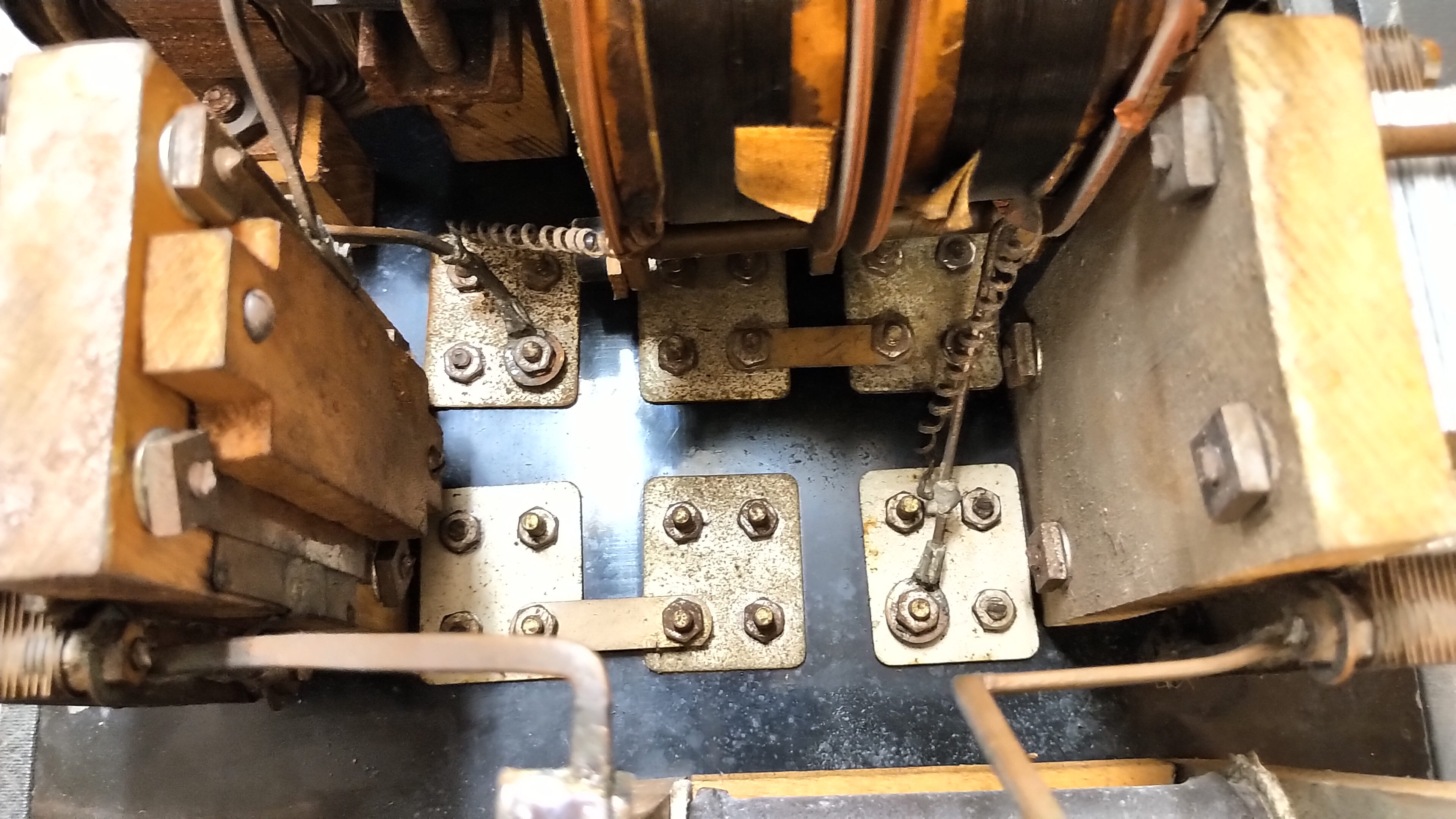
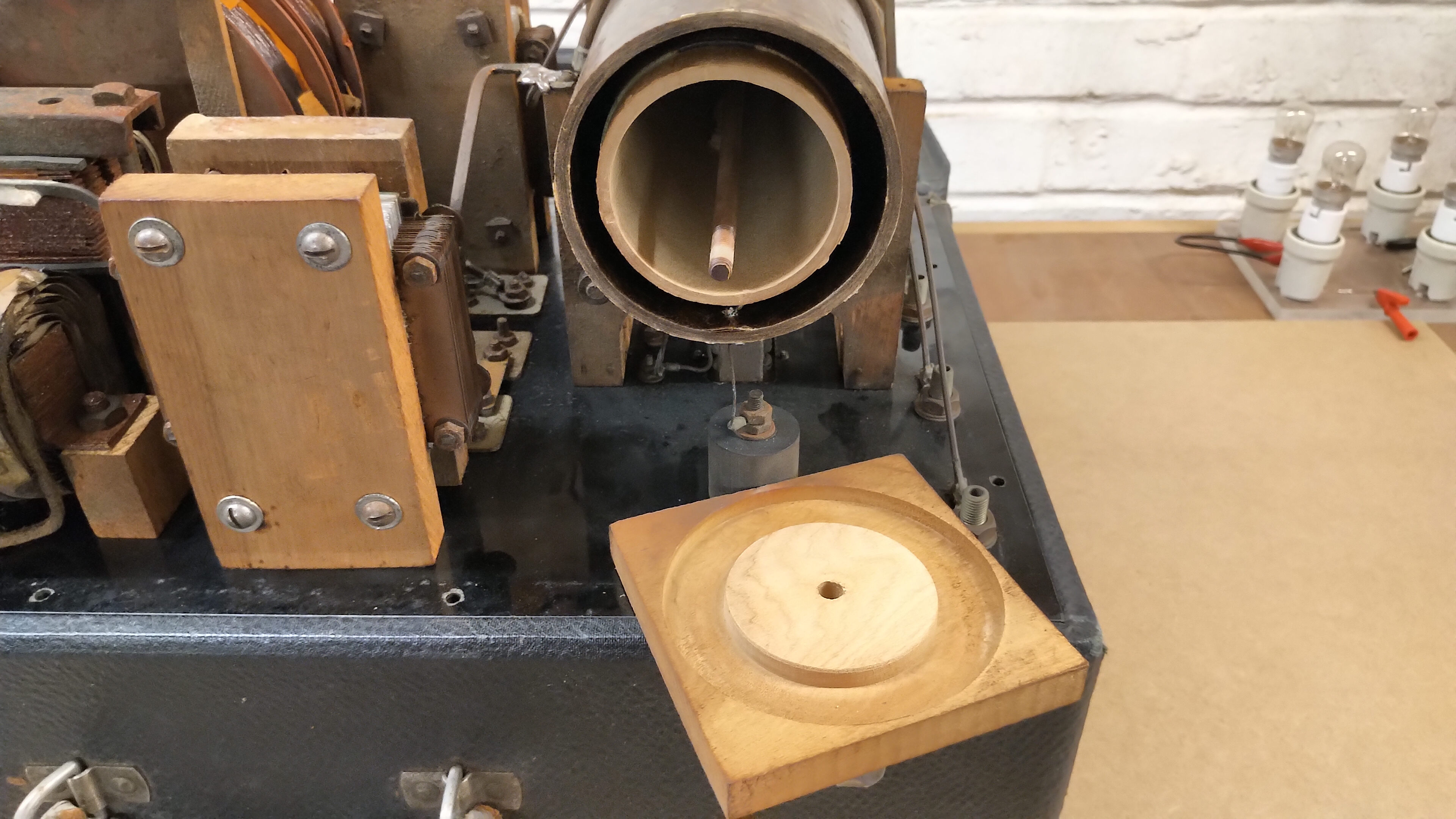
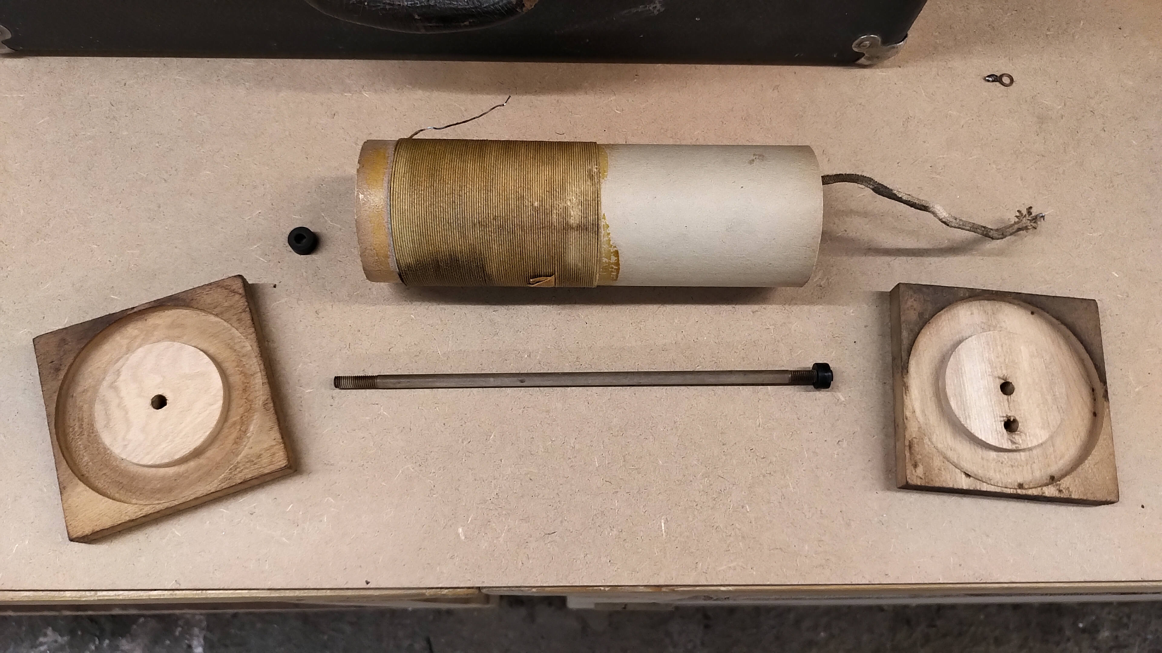
The two tank capacitors are connected to each end of the primary coil, which is 6 turns of 3/16” copper tube, and then extended by an 11 turn AWG 12 solid copper wire Oudin coil extension. The low, medium, and high output taps are then derived from the primary and Oudin extension as shown in the schematic diagram of figure 2. The primary and Oudin extension are wound around a 31/2” primary former which appears to be a resin/mica composite material. The primary turns are separated from each other by a cotton woven thread which matches the diameter of the copper tube and wire. Connection between the spark gaps and the tank capacitors, the primary coil, and the output taps, are via 3/16” x 1/16” solid copper flat bar.
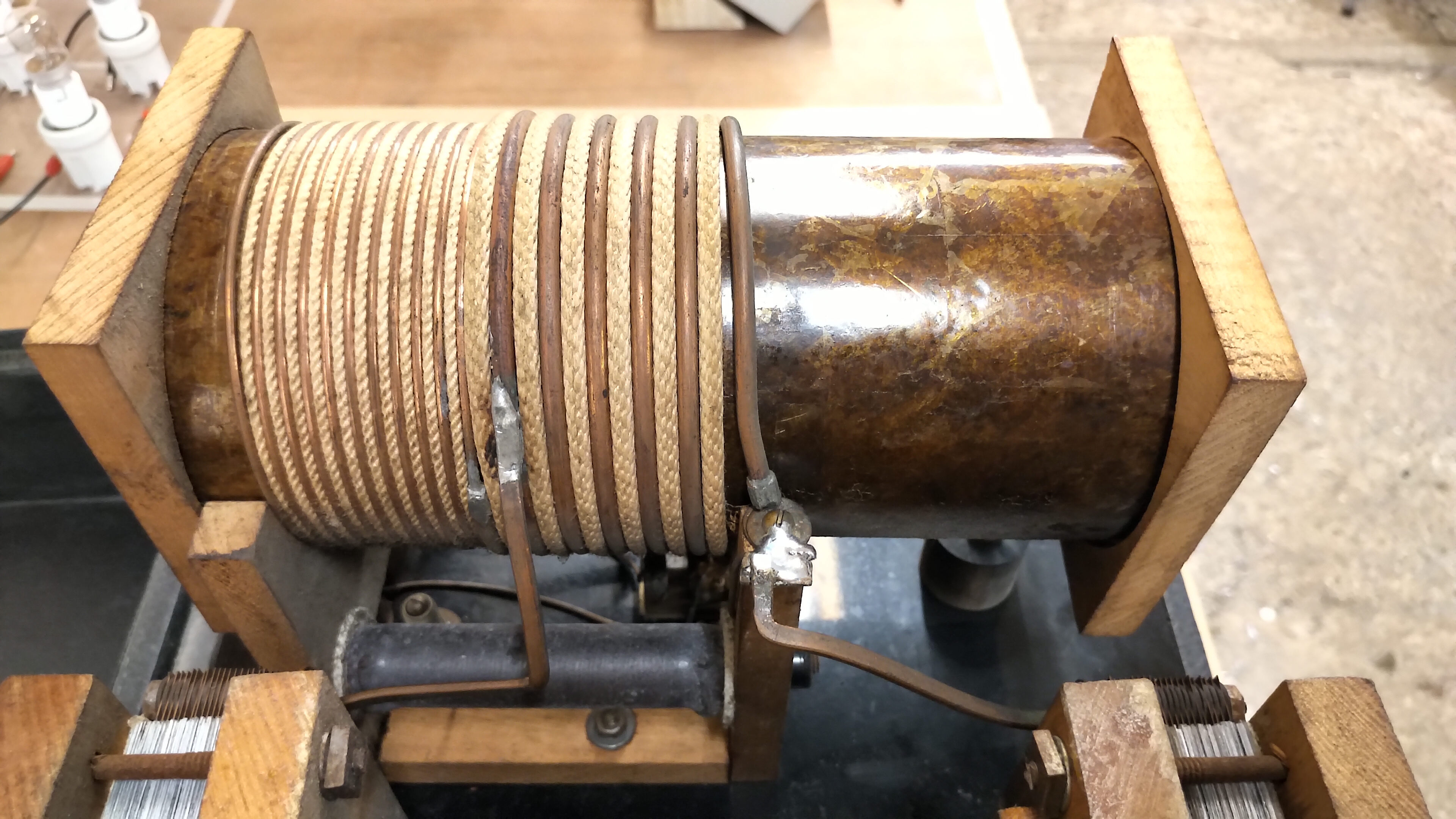
The secondary coil is a 90 turn 20 AWG cotton coated magnet wire on a 25/8” cardboard former, and the turns retained in place by the same Shellac type resin. The secondary coil is retained in the centre of the primary former by two wooden end caps, themselves compressed together by another insulating fibre threaded rod, with plastic threaded round nuts. The inner end of the secondary is connected to the common connection as shown in the schematic, and the other outer “hot” end of the secondary is fed through the centre of a bakelite stand-off/insulator through the front-panel and to the high tension Tesla terminal, (ball connector with 4mm socket hole). It is important to note that the secondary coil is orientated within the primary former at the opposite end to the Oudin coil extension, which prevents the very high tensions at the top-end of both the primary and secondary from breaking through the primary former forming a spark discharge path between primary and secondary coils.
The primary output taps are connected through a manually positioned thermo-ammeter shunt that shows rf output current on two ranges 0-1A, and 0-4A. The manual shunt can be positioned to remove the meter from the circuit, or to connect it in high and low range positions. The low range is protected by a 1A slow-blow fuse that shunts a 22Ω 50W wire-wound power resistor. When the fuse blows the shunt across the resistor is removed and the meter is protected by the series power resistor. The overall low-side output of the manual meter/shunt circuit, is connected to the indifferent (ground) terminal on the front-side of the diathermy main panel. The measured component parameters combined with their important physical attributes are shown on the schematic in figure 2.
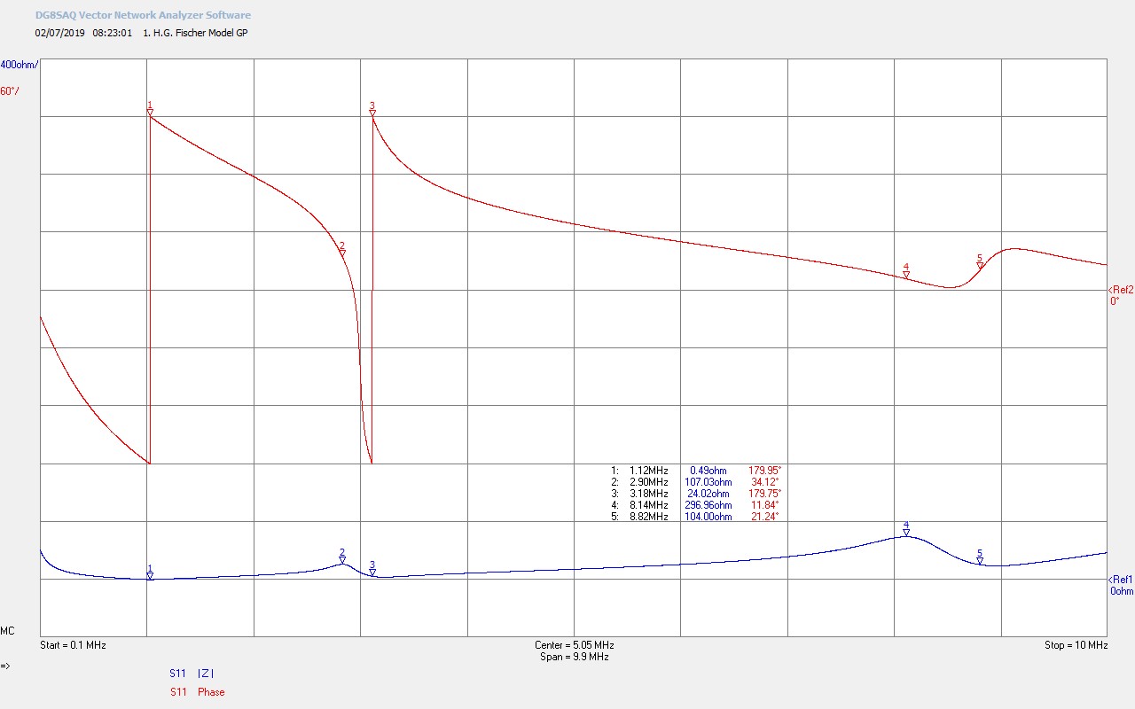
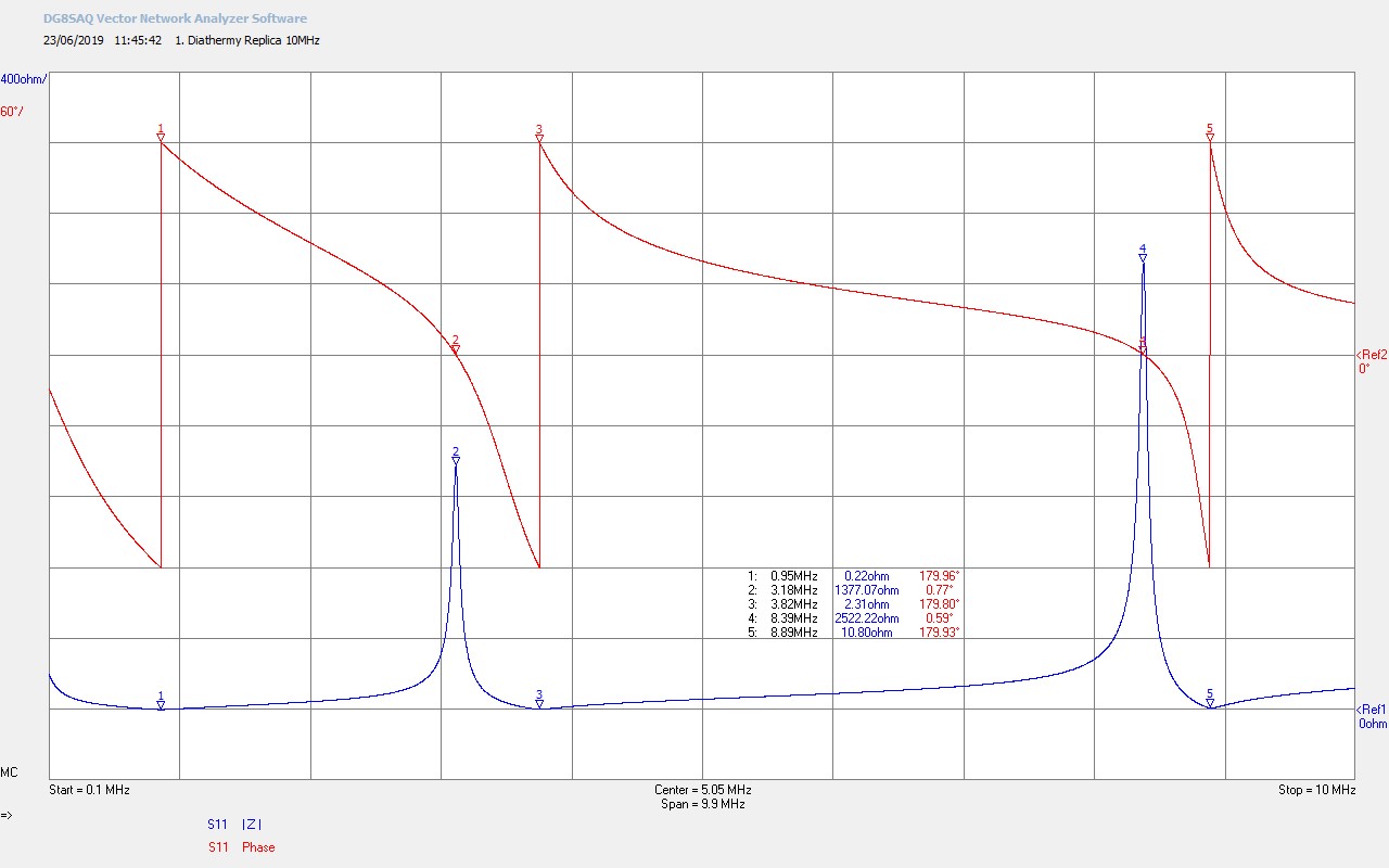
Figures 3 below show the small signal impedance measurements for Z11 up to 10Mc/s at the output of the spark gaps for both the original HGF and the diathermy replica (DR) unit:


To view the large images in a new window whilst reading the explanations click on the figure numbers below, and for a more detailed explanation of the mathematical symbols used in the analysis of the results click here.
Fig 3.1. Shows the fundamental resonant frequency FP at M1 of the primary circuit, and the fundamental for the Tesla secondary coil FS at M2, and its second harmonic FS2 at M4. FP at 1120kc/s is the series resonant frequency formed by the combination of the two series tank capacitors CP connected together by the spark discharge, in series with the primary coil inductance LP. LPCP forms a series resonant circuit where the reactance of LP and CP cancel each other out at resonance, leaving only the series resistance of the primary RP at M1, which in this case is 0.49Ω.
M2 shows the fundamental resonant frequency of the secondary FS = 2900kc/s, and M3 the frequency at which a 180° phase change takes place FØ180 = 3180kc/s. As is normal for a secondary coil where there is considerable distributed resistance across the coil end, points FS and FØ180 do not occur at the same frequency, and the parallel resonance formed between LS and the distributed capacitance CS set the fundamental resonance of the coil at M2. When electrical energy is coupled to the secondary from the primary the coil will resonate at the frequency indicated at M2. It is also to be noted that the Q of the resonance at M2 is considerably lower than expected, showing that losses in the secondary coil, materials, and mountings are considerable, where rf energy is being both dissipated in RS, and leaking out of the circuit formed by LSCS through parasitics to the surrounding medium. The low Q of the secondary considerably impacts the energy stored in the system, and will reduce considerably the rf oscillating currents in the secondary, which can be seen in figures 3.
The second harmonic of the secondary FS2 occurs at M4 and M5. If the primary is tuned closer to M4 then the secondary coil will resonate at FS2 = 8140kc/s which represents the second odd harmonic of the secondary wire length, 3λ/4. The parallel resonance at M4 is noted also to be very low Q, and similar in this case to the fundamental. The low Q of the secondary can most likely be attributed to, firstly, the cardboard former of the secondary coil, which over considerable time will have absorbed moisture, and presents a considerable leakage or parasitic resistance to the windings of the secondary coil. Secondly, the windings in themselves are only cotton-clad un-insulated (bare) magnet wire, which also presents a significant leakage path to a moisture impregnated cardboard former. Thirdly, the cardboard former is mounted to the primary via wooden end boards which themselves can absorb moisture, and when combined with moisture in cardboard former of the secondary could also form a significant leakage between the windings of the primary (bare copper) and the secondary coils. It is conjectured that the Q of the secondary when the HGF was new, or much younger, would have been better than now measured, but still due to the nature of the materials used, would still present a much lower Q than that which can be obtained by using plastic formers, and with magnet wire either PTFE coated, or high temperature varnish coated.
Fig 3.2. For comparison the same small signal impedance measurement is shown from the spark gap generator diathermy replica (DR). Due to the slightly different geometric sizes, of the readily available materials used, for the primary and secondary, and the modern equivalent of the tank capacitors, the key resonant frequencies of the primary and secondary are at slightly different points. However the general characteristics of the frequency markers remains very similar on the horizontal scale. The series resistance of the primary circuit at resonance for the DR is less than half that for the HGF, showing that larger primary currents can be generated in the DR providing stronger output currents in the low, medium, and high primary taps.
The big difference between the HGF and DR is in the Q of the secondary coil, which is very much larger, and well-defined, in the case of the DR. This shows the difference largely between the types of materials used to construct the secondary, which in the case of the DR is a plastic polypropylene former, with PTFE coated Kynar secondary windings, insulated from the plastic polypropylene former of the primary, by nylon 66 connecting bolts. All these plastic insulating mediums do not suffer with moisture absorption over time, do not degrade significantly over normal time spans, and present a very high impedance between the primary and secondary coils, which reduces any leakage currents in the secondary to very low values. Hence the Q of the secondary circuit is very sharp and well-defined.
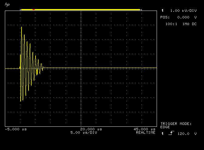
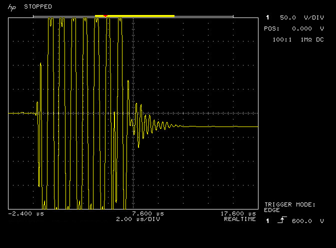
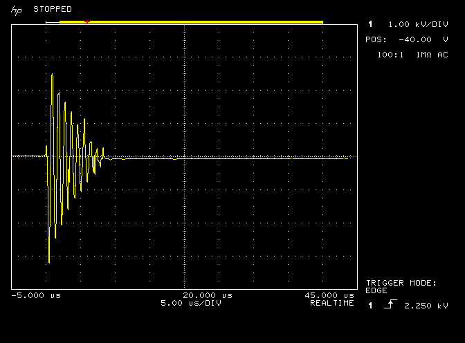
Figures 4 below show the large signal time domain waveforms of the HGF as measured from the indicated output taps, and illustrate the different stages of the spark discharge burst both in the primary and secondary coils of the generator. The HGF was being run at an input power of ~ 300W, (monitored using a Yokogawa WT200), which was kept constant throughout the measurement. Output waveforms were measured using a Pintek DP-50 high voltage differential probe, (max. 6.5kV up to 50Mc/s), which was connected to a HP 54542C oscilloscope to observe and record the output waveforms.
To view the large images in a new window whilst reading the explanations click on the figure numbers below. For a detailed description of the different sections of the spark discharge refer to the analysis of figures 3 and 4 in Part 2 of the Spark Gap Generator post.
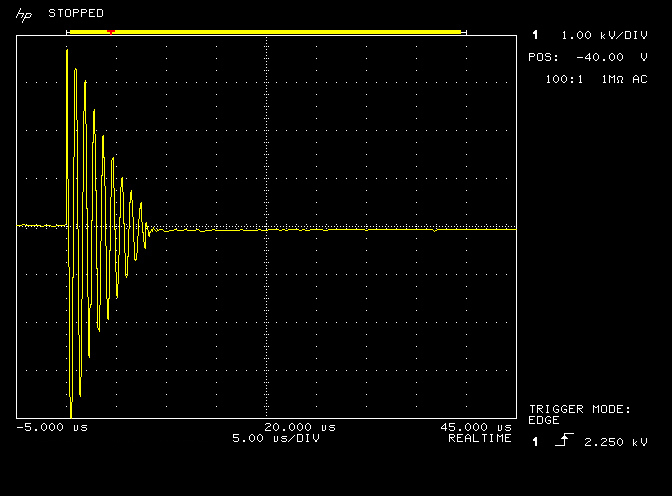
Fig 4.1. Shows the burst waveform measured at the low output tap of the HGF. The vertical amplitude scale is 1kV/div, and the horizontal timebase is 5µs/div. This figure shows clearly the second section, a ring-down of specific frequency based on an exponentially decaying oscillation in the primary coil of the HGF. The third section, a ring-down of another specific frequency on an exponentially decaying oscillation in the secondary coil of the HGF is too small to be observed on this vertical scale. The maximum amplitude of the burst is ~ 5kVpk-pk, and lasts for about 7.5µs before decaying to less than 1% of its initial amplitude.
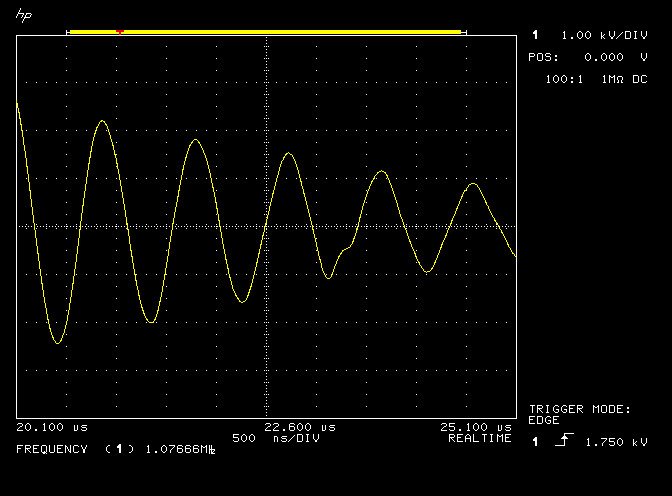
Fig 4.2. Here the horizontal timebase has been reduced to 500ns/div and the waveform buffer delay adjusted so that section two dominated with the primary oscillations fills the entire trace. The monitored average frequency of trace 1 can be seen to be 1077kc/s which is FP, the fundamental resonant frequency of the primary circuit, which corresponds well to that measured in the small signal impedance measurements at M1, of 1120kc/s.
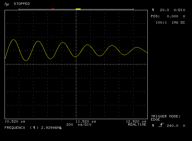
Fig 4.3. Here the vertical amplitude and horizontal timebase have been reduced from fig. 4.1, in order to show the very small third section of discharge burst, that occurs from the secondary ring-down reflected into the primary circuit. The secondary ring-down is barely 100Vpk-pk and reflects the very low Q of the secondary fundamental resonant frequency FS, as shown in fig. 3.1. Due to the low Q from the high leakage through the materials used, the third section ring-down has a low amplitude and decays away very quickly, only lasting in this case ~ 4µs after the primary ring-down in section 2.
Fig 4.4. Here the third section has been magnified and the monitored average frequency of trace 1 can be seen to be 2929kc/s, which again corresponds well to that measured in the small signal impedance measurements at M2, of 2900kc/s.
Fig 4.5. The low tap burst, again on the original scales, for amplitude comparison with the following two figures.
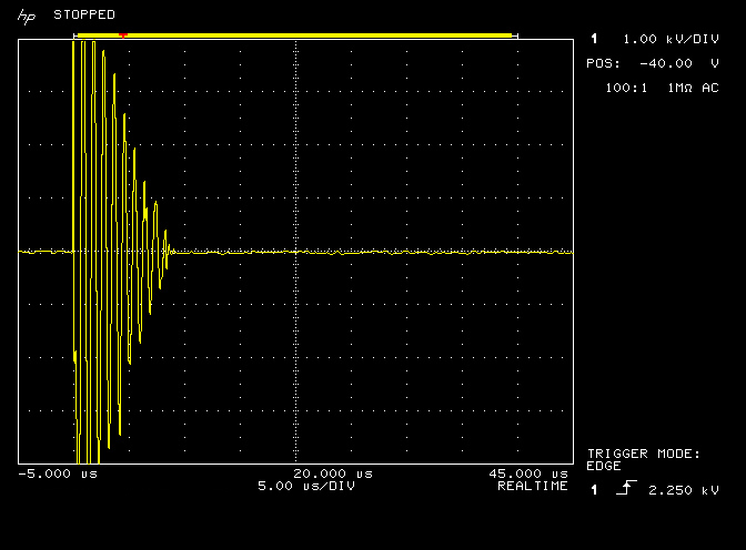
Fig 4.6. Shows the burst waveform measured at the medium output tap of the HGF, and on the same scale as before. The inital burst amplitude has increased to ~ 8kVpk-pk.
Fig 4.7. Shows the burst waveform measured at the high Oudin output tap of the HGF, and on the same scale as before. The inital burst amplitude has increased to almost 12kVpk-pk.
A comparison of some of the key characteristics of the HGF and the replica diathermy already built and reported in the Spark Gap Generator Part 1 and Part 2, are shown in the following table:
| H.G. Fischer Model GP Diathermy:
Primary Coil: 6 turns 3/16″ copper tube Primary Former (OD): 31/2“, 89.6mm Oudin extended coil: 11 turns 12 AWG solid (2mm) magnet wire Seconday Turns: 90 turns, 20 AWG cotton-clad magnet wire Secondary Former (OD): 25/8“, 65.7mm From figures 3. Z11: FP @ M1: 1120kc/s RS @ M1: 0.49Ω FS @ M2: 2900kc/s FS2 @ M4: 8140kc/s From figures 4 (large signal time domain, LSTD @ 300W): FP: 1077kc/s FS: 2929kc/s VL (pk-pk): 5kV VM (pk-pk): 8kV VH (pk-pk): 12kV |
Diathermy Replica (SGG Parts 1 and 2):
Primary Coil: 6 turns 3/16″ annealed copper tube Primary Former (OD): 90mm (standard UK polypropylene pipe) Oudin extended coil: 11 turns 14 AWG solid (1.6mm) magnet wire Secondary Coil: 98 turns, 19/32 20 AWG Kynar wire (PTFE coated) Secondary Former (OD): 63mm (standard UK polypropylene pipe) From figures 2. Z11 (Spark Gap Generator – Part 2): FP @ M1: 950kc/s RS @ M1: 0.22Ω FS @ M2: 3180kc/s FS2 @ M4: 8390kc/s From figures 3 LSTD @ 300W (Spark Gap Generator – Part 2): FP: 895kc/s FS: 3214kc/s VL (pk-pk): 4kV VM (pk-pk): 8kV VH (pk-pk): 11kV |
In summary, the original H.G. Fischer medical diathermy unit explored in this post is a robust, self-contained, and easy to use generator suitable for some preliminary experiments and replications in the field of Tesla and electricity research, where high tension oscillating currents are required, e.g. with a TMT experiment. The HGF’s lower overall performance, in comparison to the replica diathermy unit, largely results from age related wear and tear, component degrading, and generally lower quality, or less suitable, materials for high voltage applications. Having said this, the HGF is almost 100 years old, and still working more than adequately as a high voltage generator, which is in itself an impressive accomplishment from another time. Without access to an original HGF, it has been shown in other posts, that a good high performance generator with very similar yet improved characteristics, can be constructed using readily available materials at a very affordable cost.
Click here to continue to part 1 of the spark gap generator where the diathermy replica is designed and constructed.
1. Tesla, N., Experiments with alternate currents of very high frequency and their application to methods of artificial illumination, American Institute of Electrical Engineers, Columbia College, N.Y., May 20, 1891.
2. Kraakman, N., A Brief History of the Tesla Hairpin Circuit, December 7, 2017, Waveguide