In this first part we will look at both video experiments and measurements to investigate and demonstrate the transference of electric power via the transmission medium of a single wire, and combined with and without multiple loads. The experiments are undertaken using the flat coils designed, measured, and tested in detail here. Part 1 of this topic is intended to experimentally introduce the transference of electric power, and the various properties, phenomena, and effects that can be measured within such an electrical system when excited using the vacuum tube generator as a feedback oscillator, details here.
A more detailed introduction to the principles of transference of electric power can be found here. The experimental work in this part is intended to investigate and demonstrate aspects of the following:
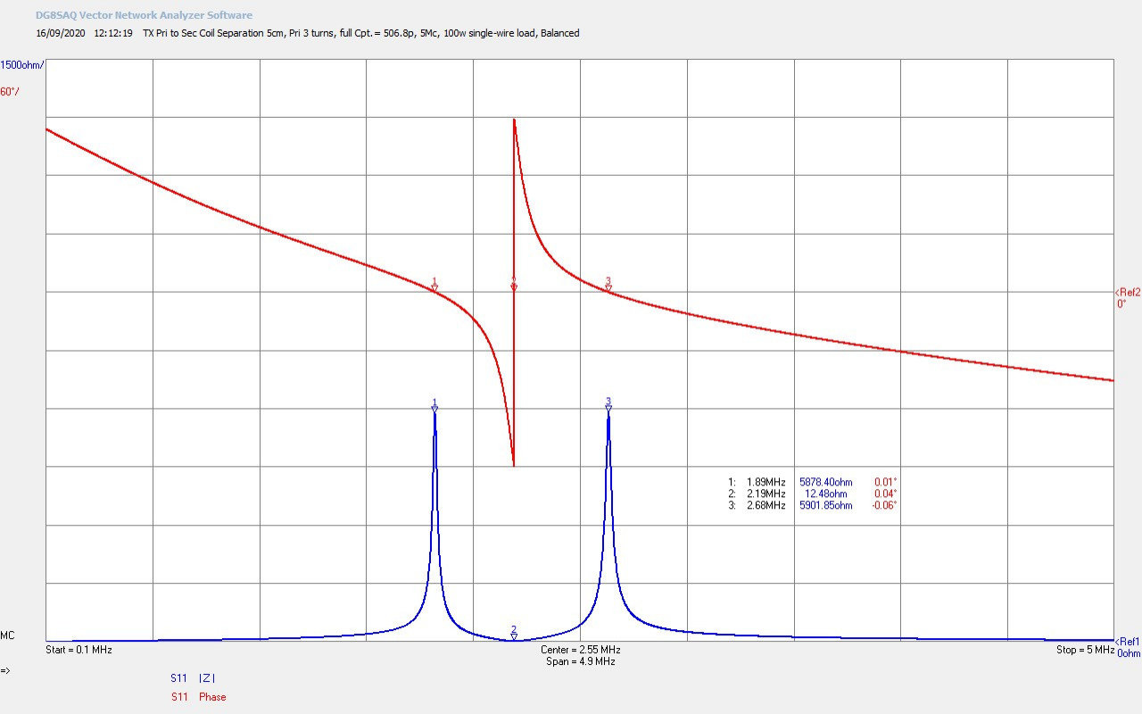
1. Tuning measurements using a vector network analyser to measure Z11, the small signal ac input impedance for the experimental system, from the perspective of the generator.
2. Tuning the transmitter and receiver to different points to demonstrate different transference phenomena.
3. Single wire transmission and the longitudinal magneto-dielectric (LMD) mode.
4. Tuning to power a load within the single wire transmission line.
5. Tuning to power a load at the output of the receiver.
6. Tuning to establish the LMD mode of transmission between the transmitter and the receiver.
7. Tuning to establish the null point of the LMD mode within the single wire load.
8. Tesla’s wireless transmission of electric power in the near field, using a pair of tuned Tesla magnifying transformers (TMT).
9. Transference of electric power between the transmitter and receiver in the near field.
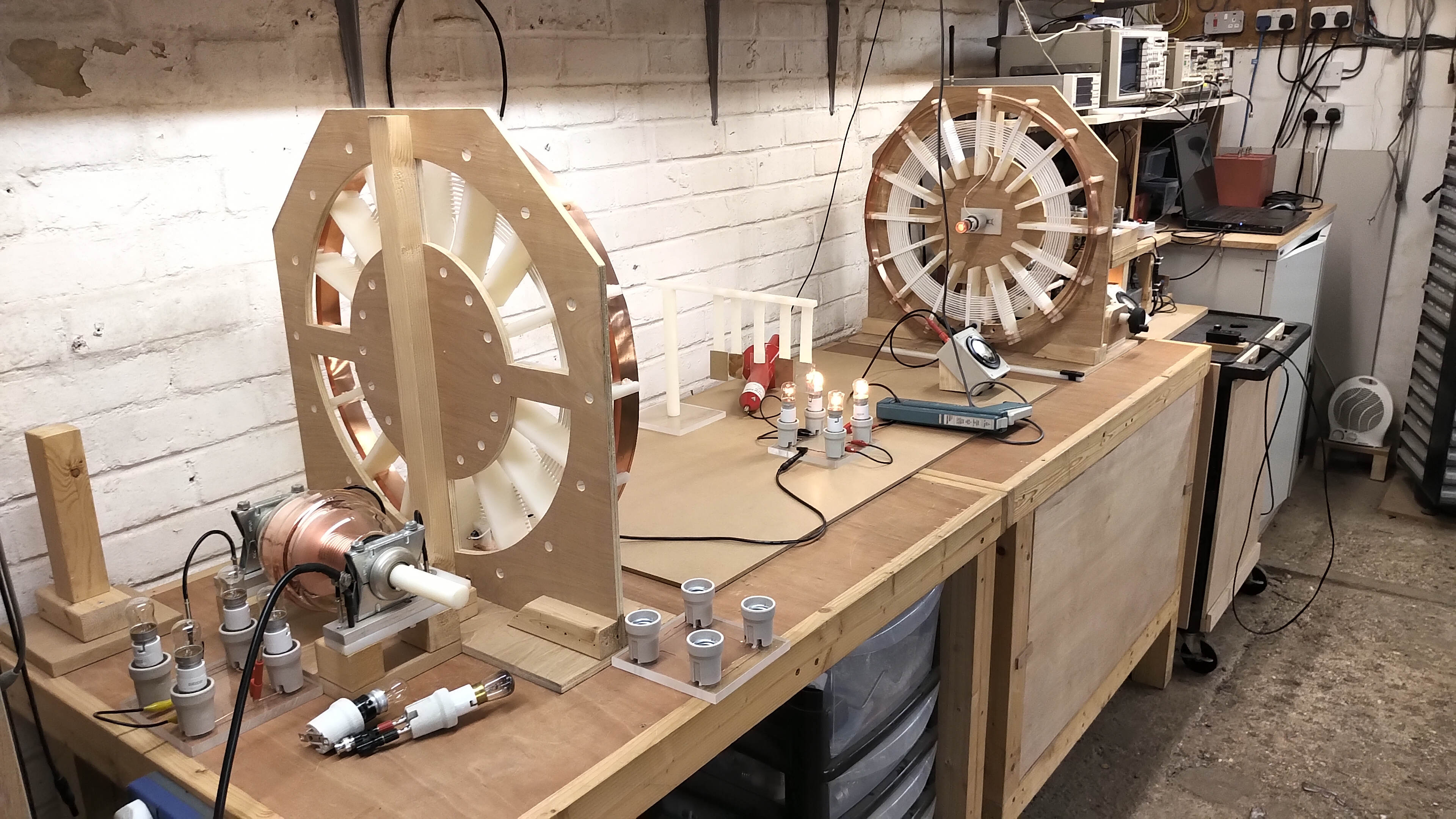
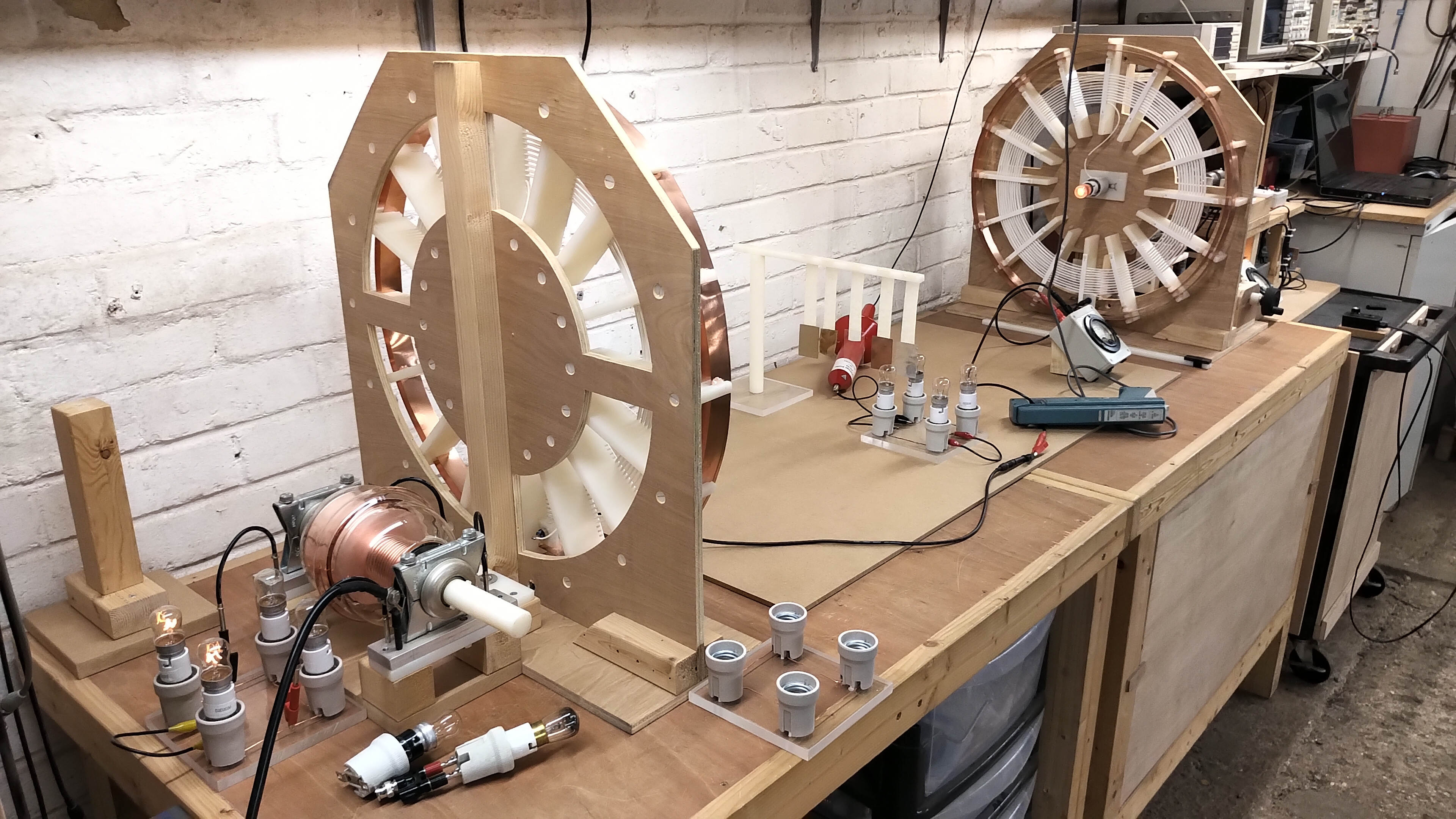
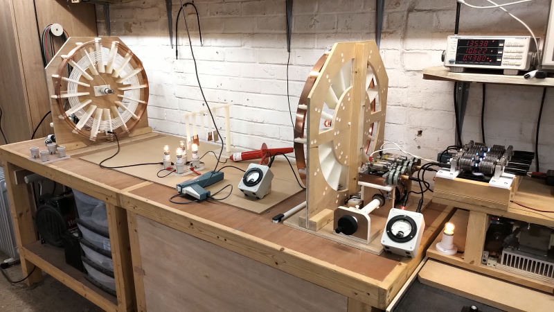
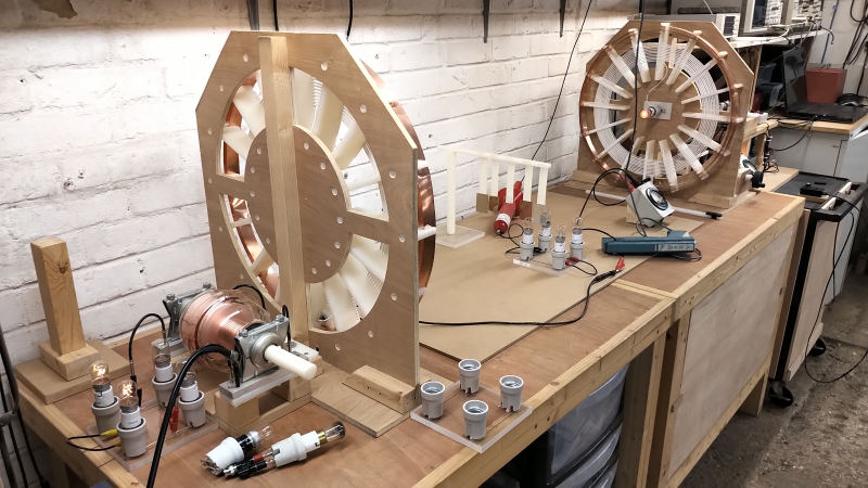
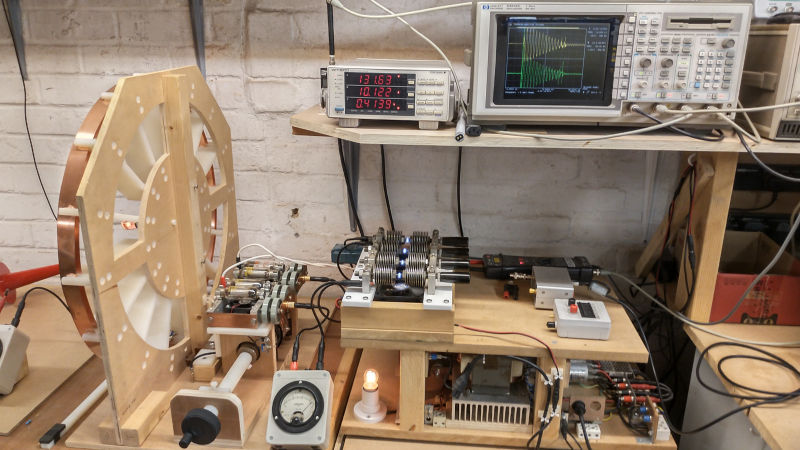
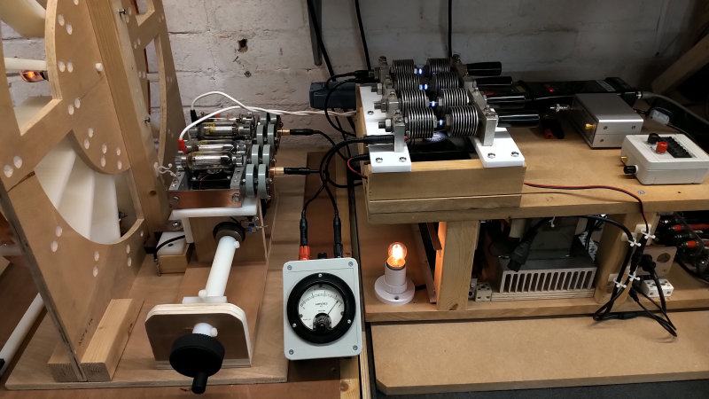
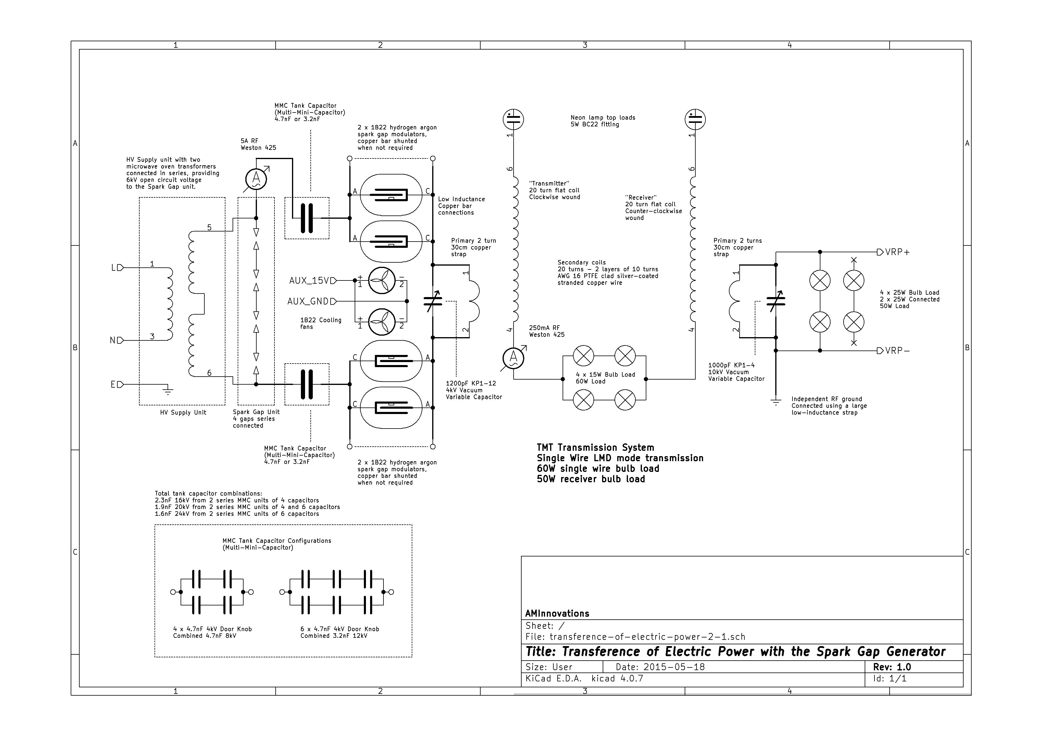
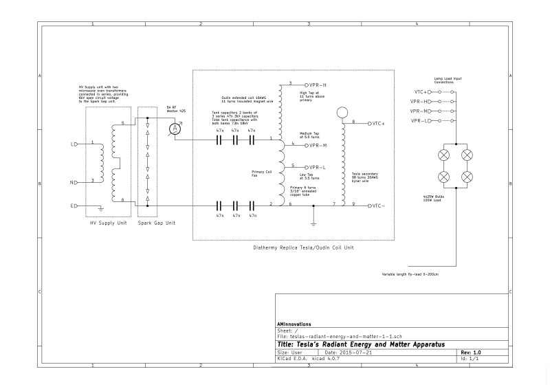
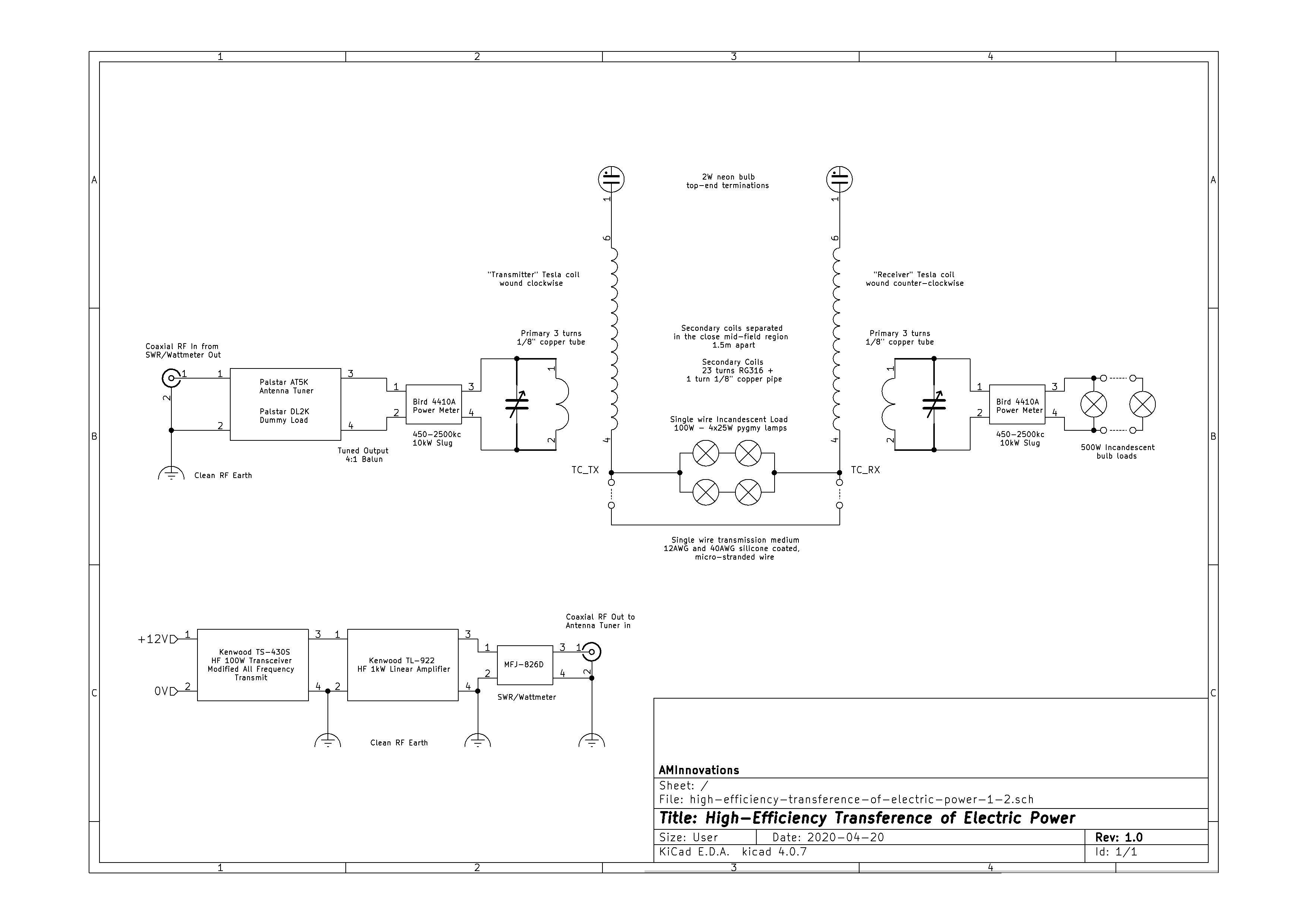
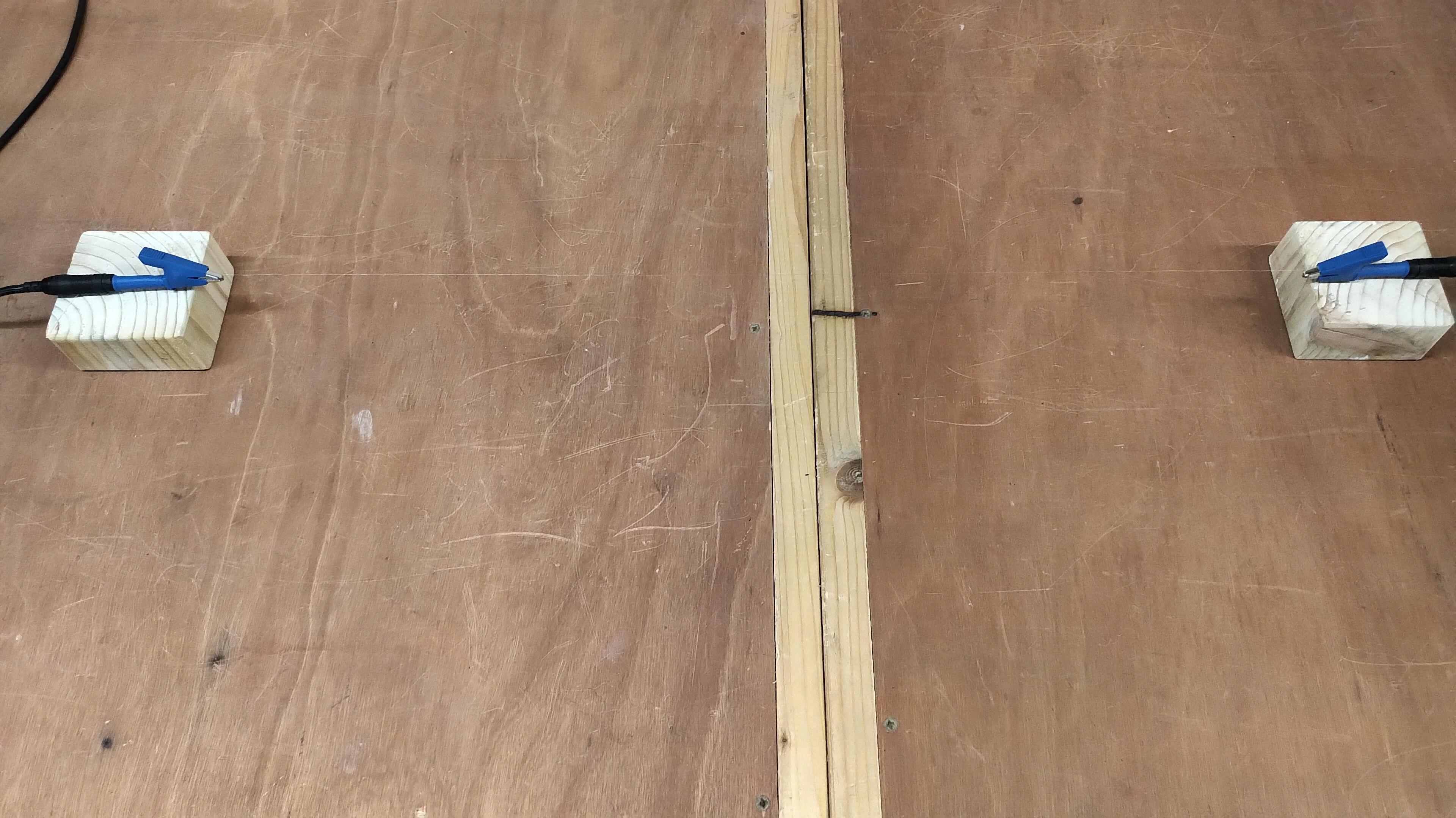
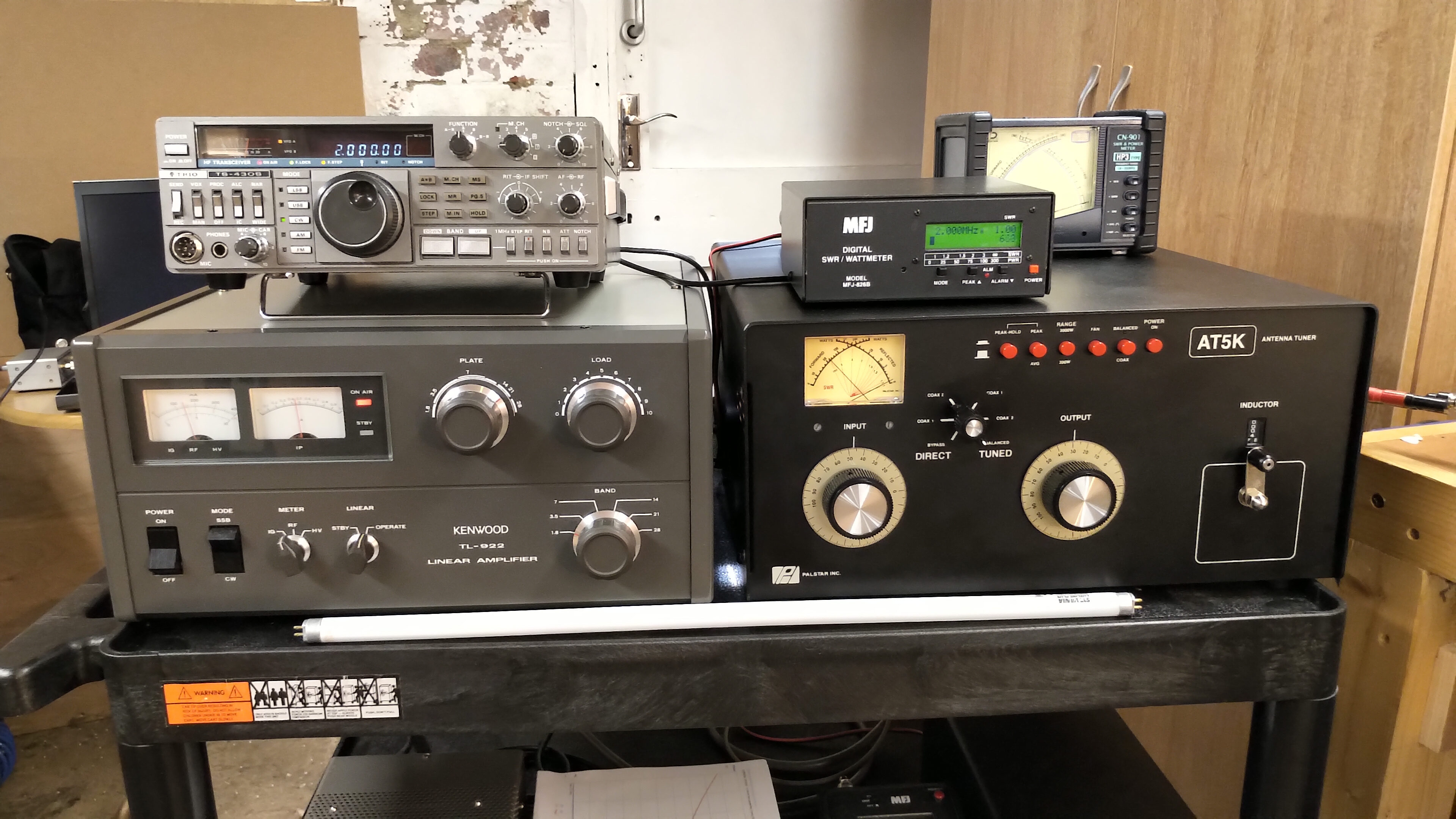
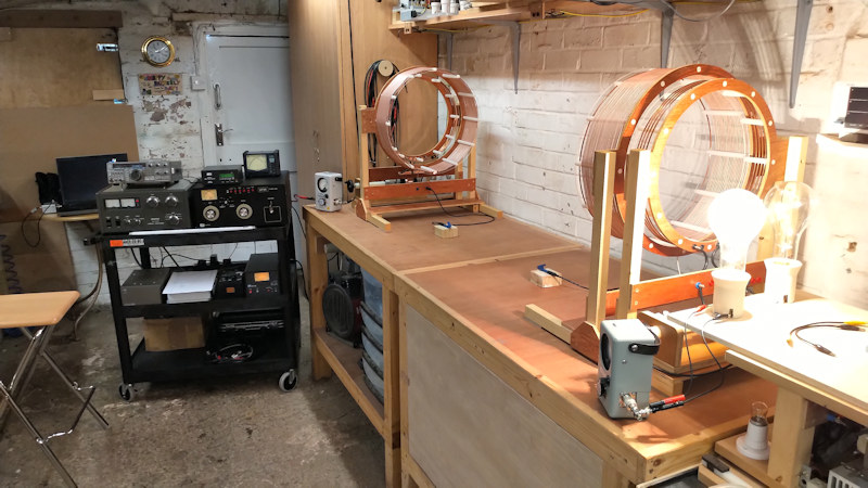
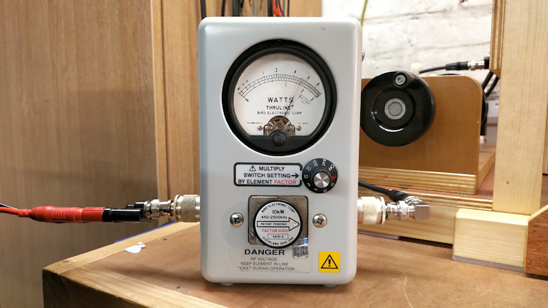
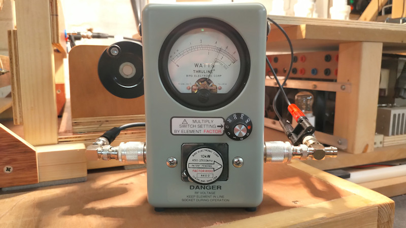
Figures 1 below show an overview of the experimental arrangement which consists of two flat coils used as transmitter and receiver and joined via the base of the secondary coils by a single wire transmission line with an inline 100W four incandescent lamp load, (4 x 25W 240V pygmy lamps). The transmitter primary is connected to the 811A vacuum tube generator via a matching unit which in this case consists of only a 1200pF vacuum variable capacitor in parallel with the 2 turn copper strap primary. The receiver primary is tuned by another parallel connected 1000pF vacuum variable capacitor which in turn is connected to another 100W four incandescent lamp load. The outer end terminal of the receiver primary is connected directly to RF ground via a low inductance ground strap. The secondary coils of the transmitter and receiver are positioned facing each other on axis 1.5m apart, and are counter-wound to each other in order to produce a balanced and reciprocal cavity arrangement.

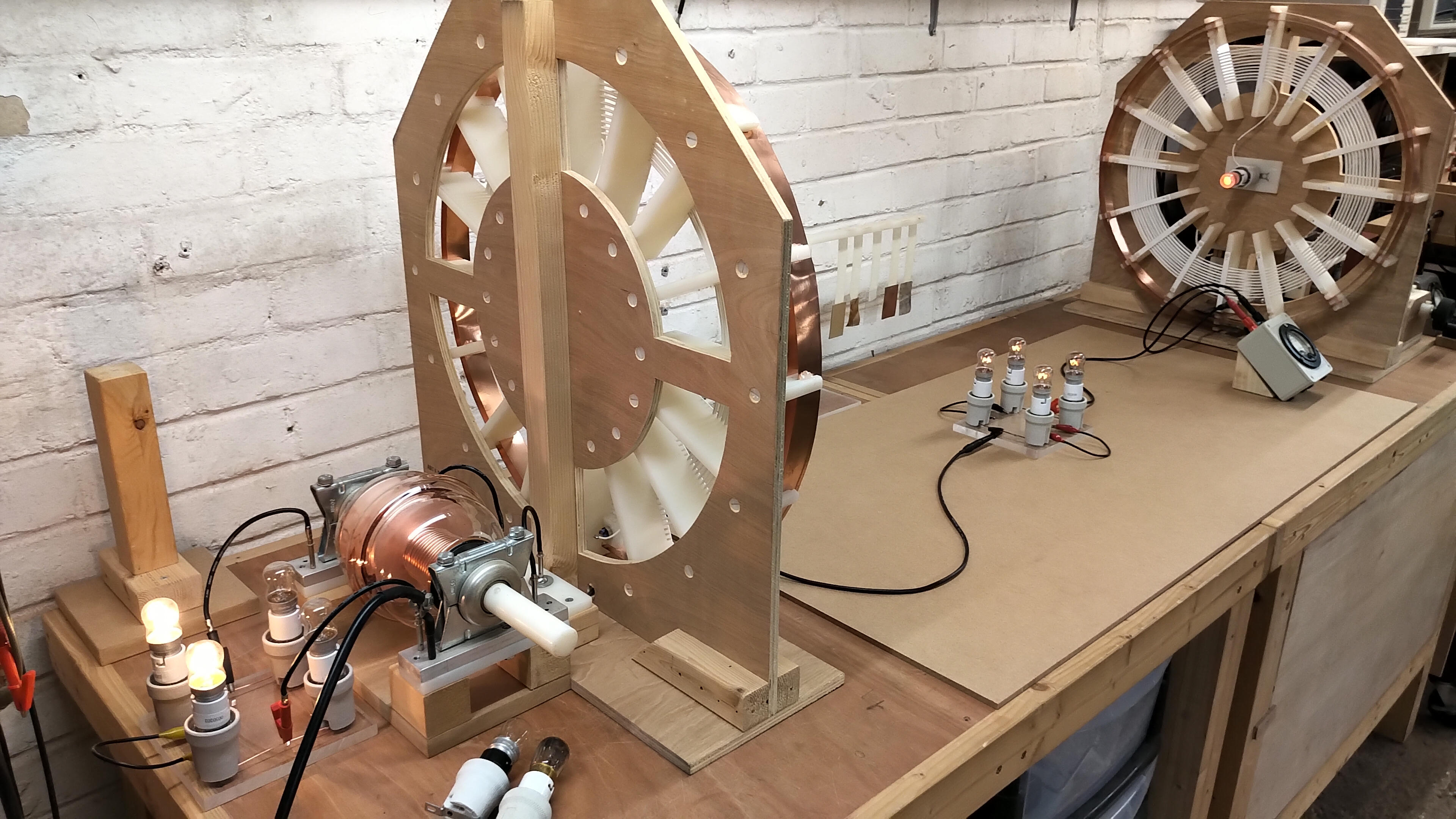
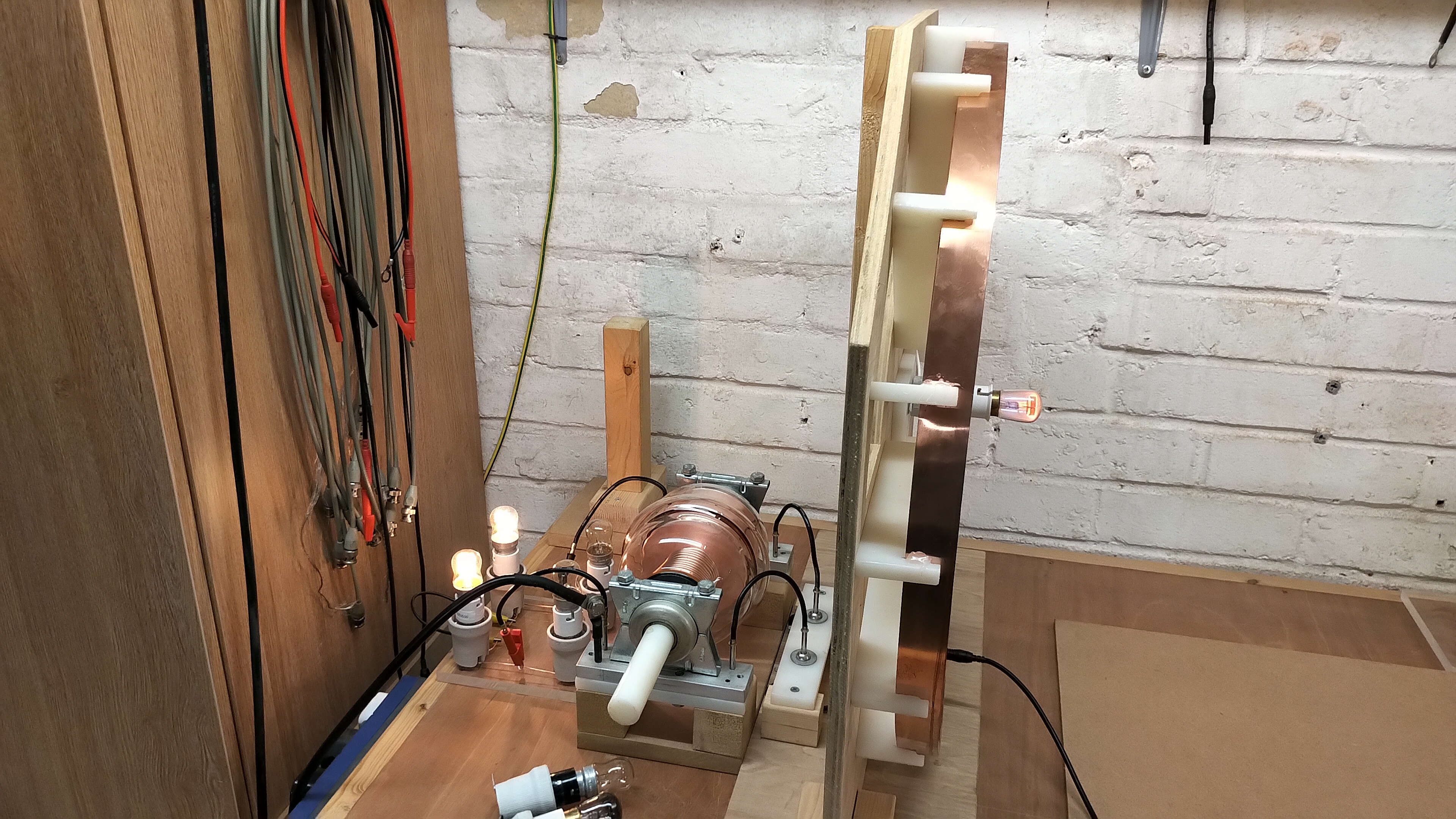

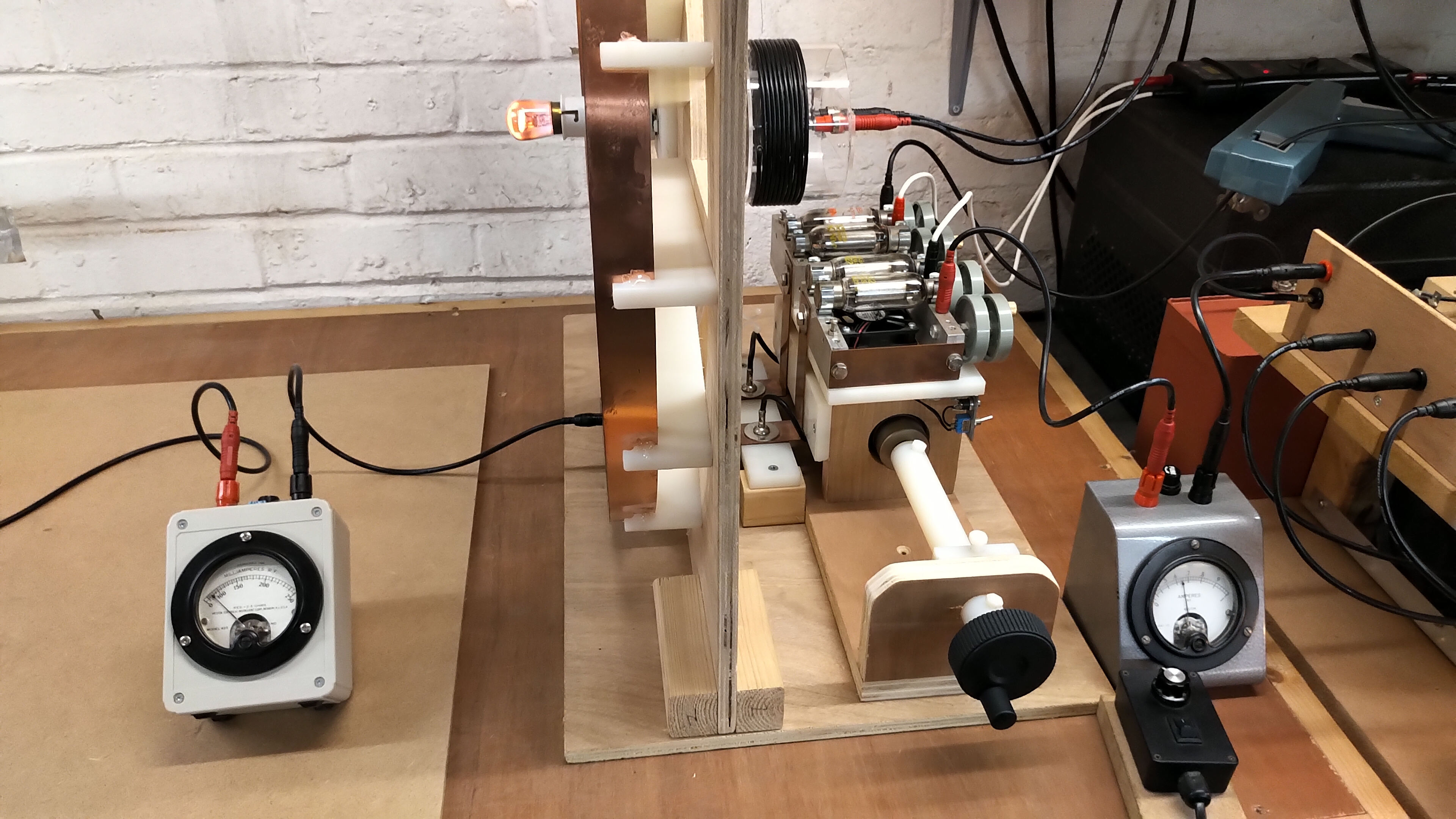

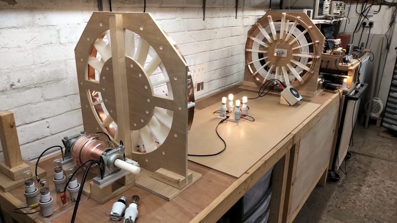
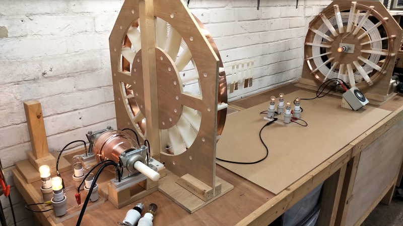

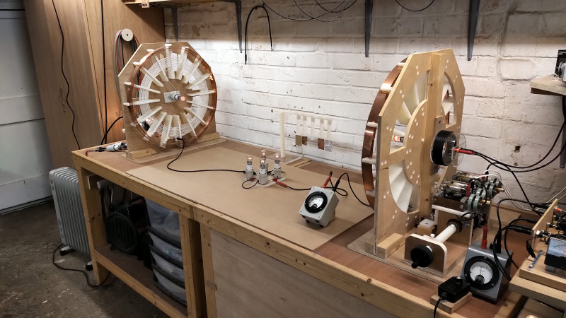

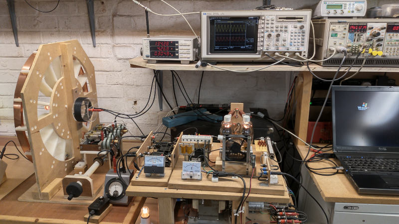
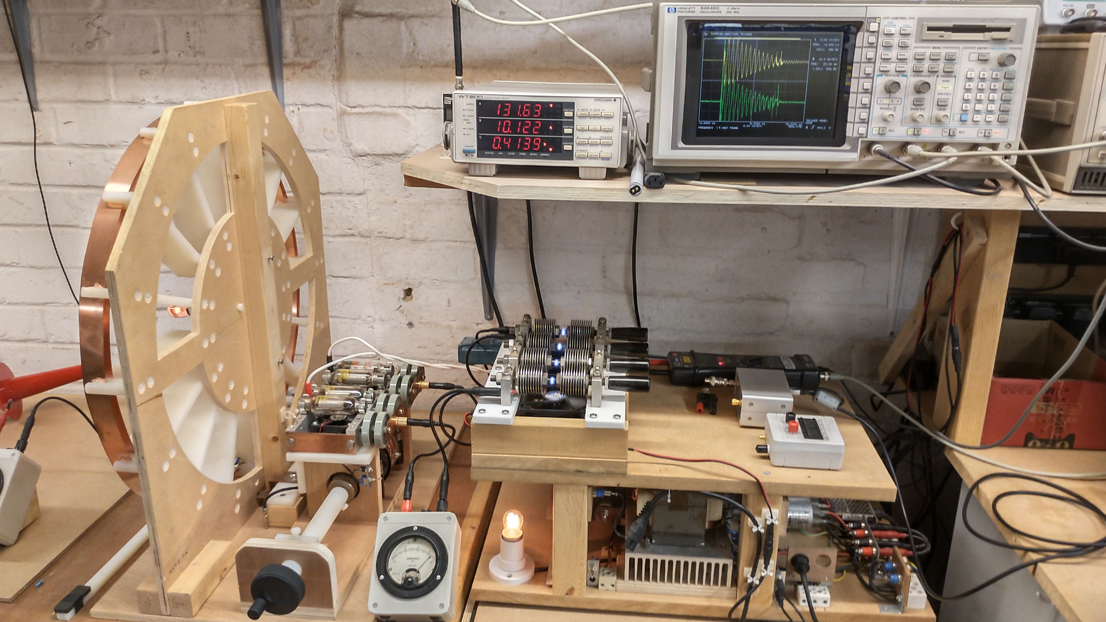
The 811A vacuum tube generator is used in this experiment as a tuned plate class-C Armstrong oscillator which derives automatic feedback from a pick-up coil placed close to the secondary coil of the transmitter, and can be clearly seen on the back of the transmitter in figures 1.4-1.6. The advantage of using a self-tuned oscillator as the generator for this experiment is that complete tuning of the system can be easily accomplished simply by adjusting CPT, the primary capacitance of the transmitter, (and for fine tuning CPR the primary capacitance of the receiver). As CPT is adjusted over its range the generator tracks the tuning changes in the overall system allowing very precise and optimum frequency tracking through the various resonant bands of the system.
The dis-advantage of self-tuning the generator in this way, is in the regions where there is very little coupling between the primary and secondary of the transmitter coil, (far from the resonant regions), there is insufficient feedback to the vacuum tubes and oscillation can be unstable or non-existent. To explore these low coupling regions a fixed frequency excited linear amplifier would be the preferred choice, which will be covered in another part. For this part in exploring the transference of electric power via transmission between a transmitter and receiver coil via a single wire transmission line, we are most interested in the resonant regions of the system where the self-tuned oscillator allows for convenient and accurate tracking within these bands.
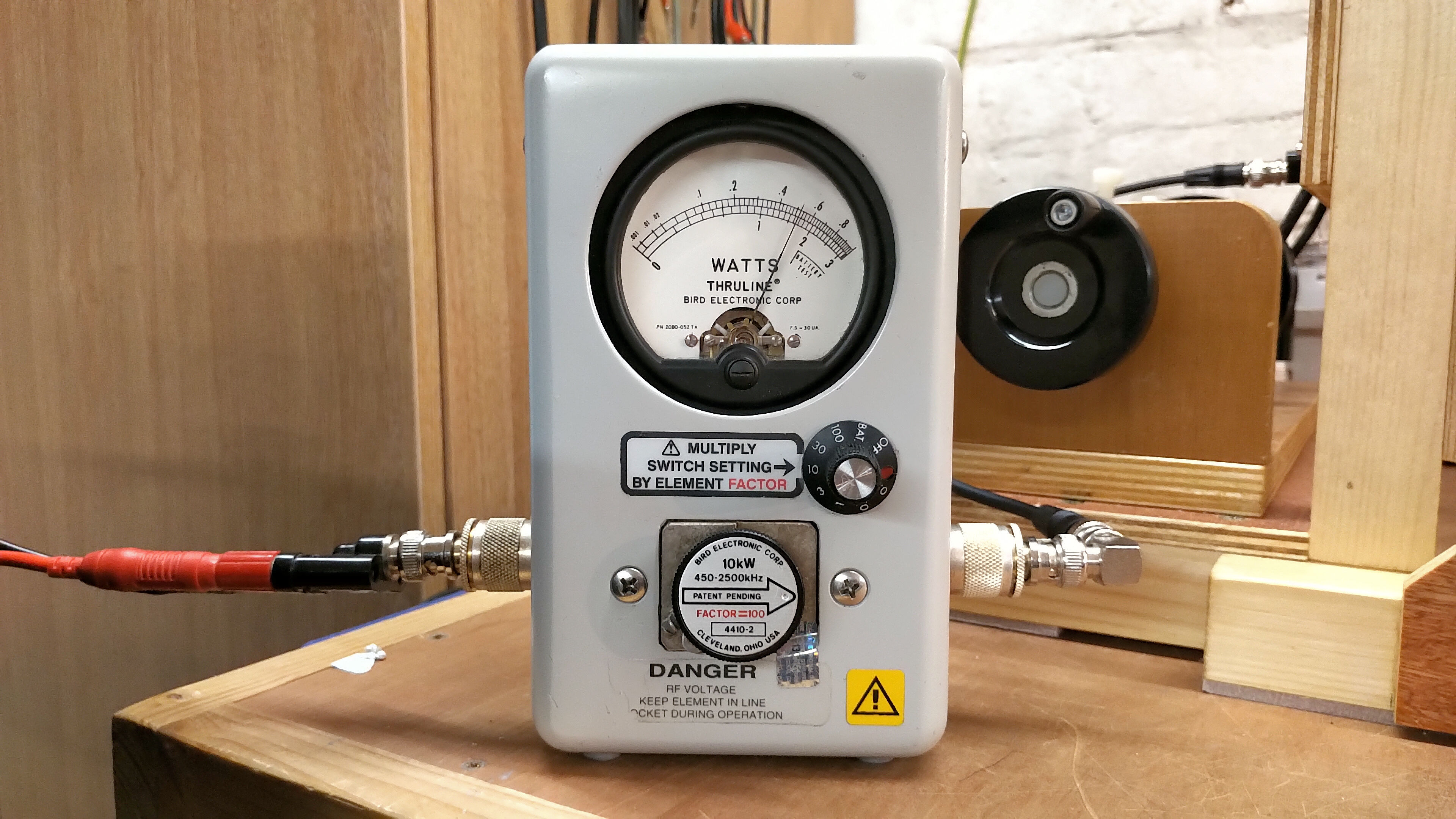
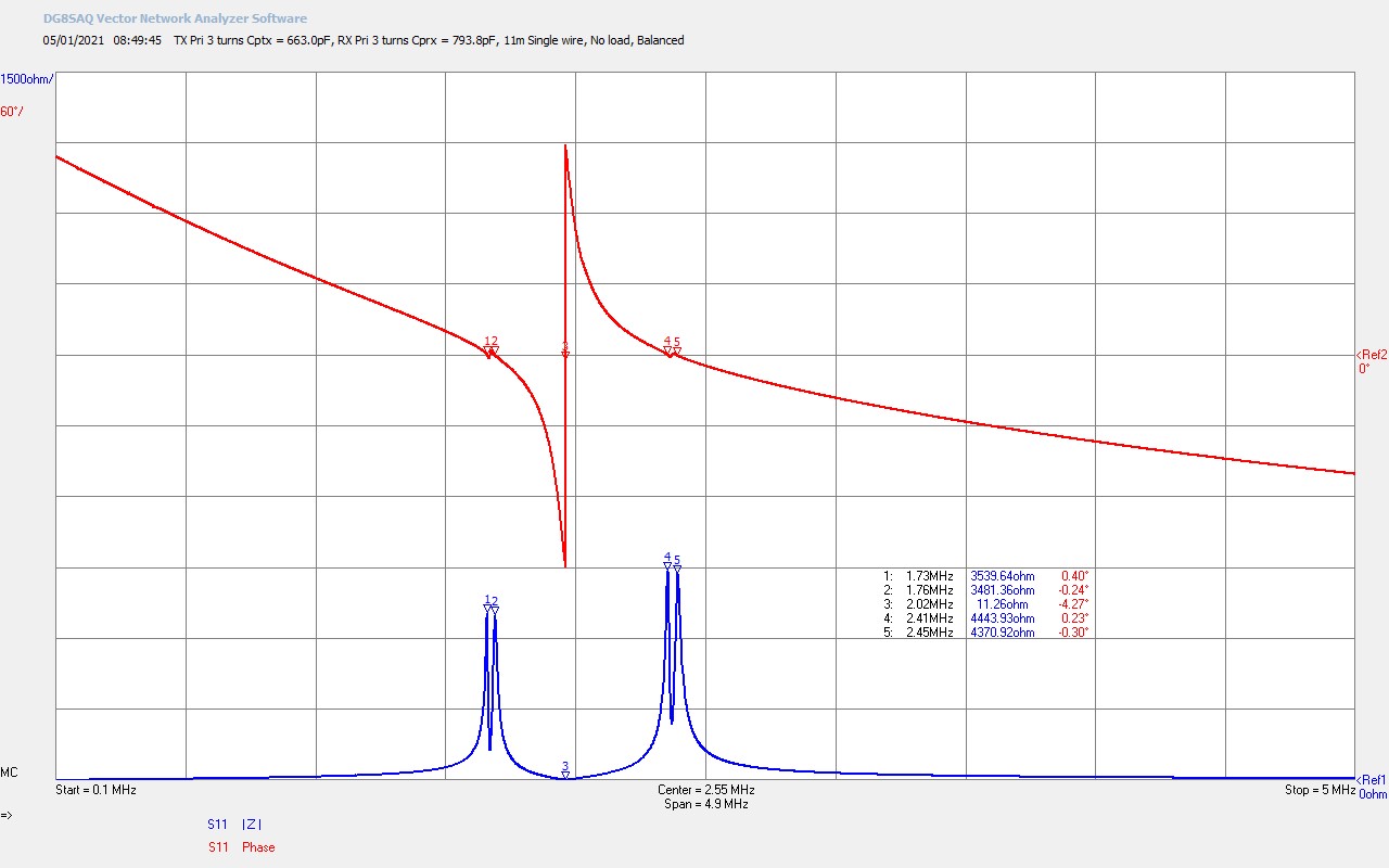
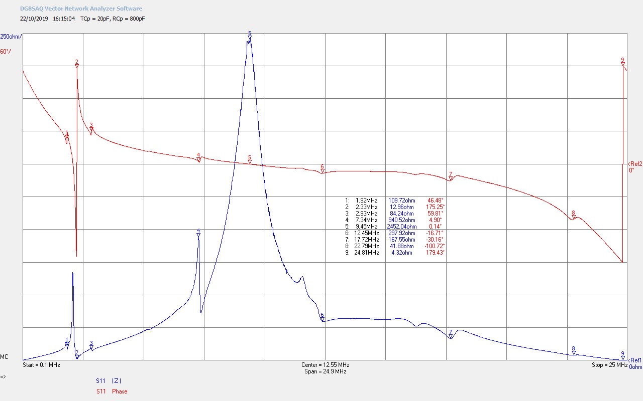
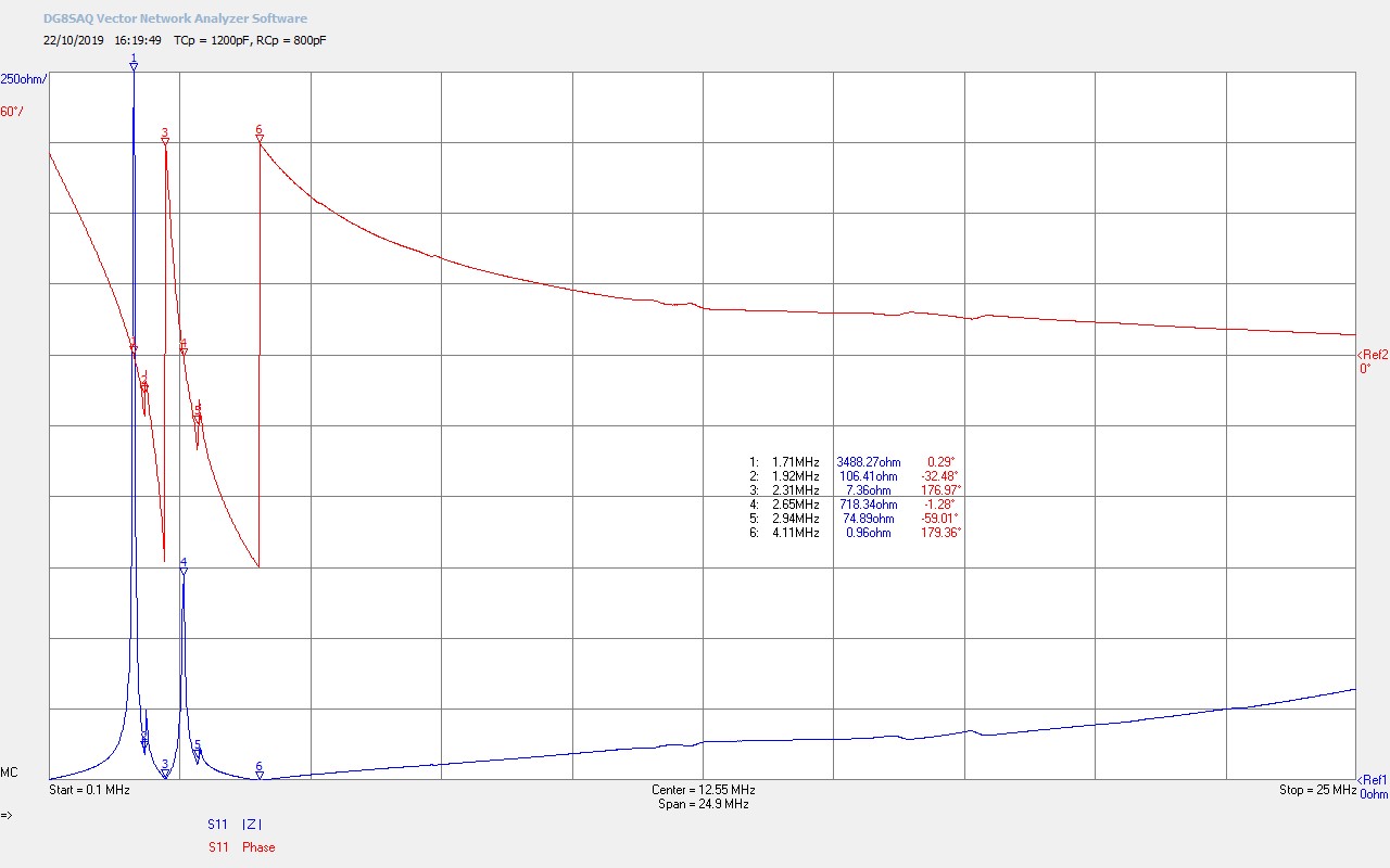
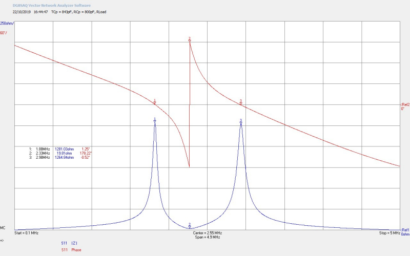
The first video introduces the experimental setup, instrumentation, and readings, and then looks in detail at the Z11 small signal impedance characteristics for a range of different tuning conditions for both the transmitter and receiver coils, combined with a single wire transmission medium, and both with and without multiple incandescent lamp loads.
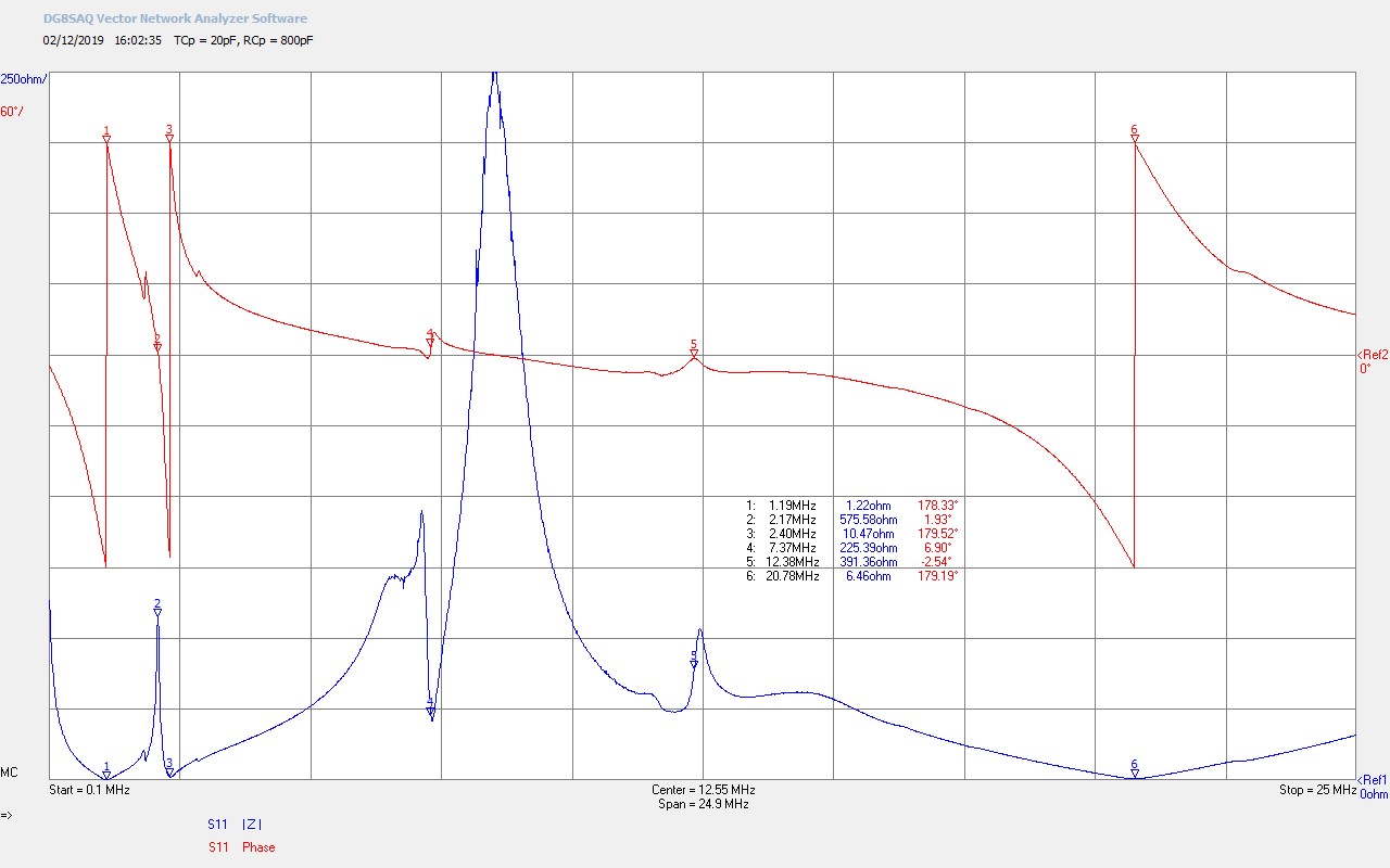
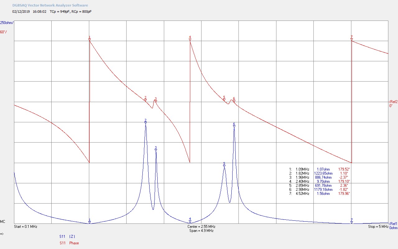
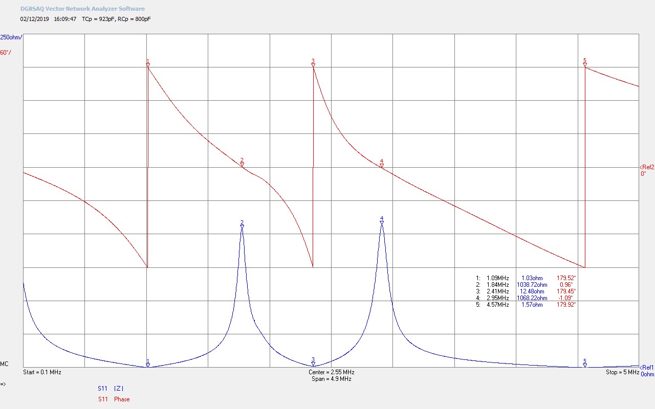
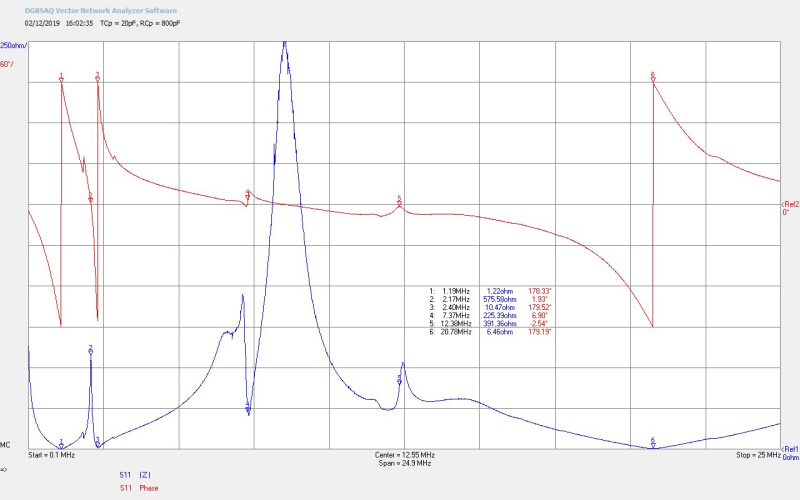
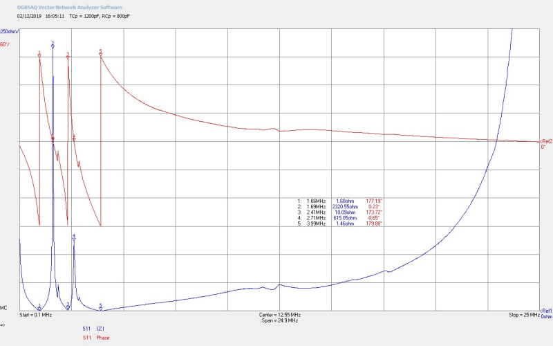
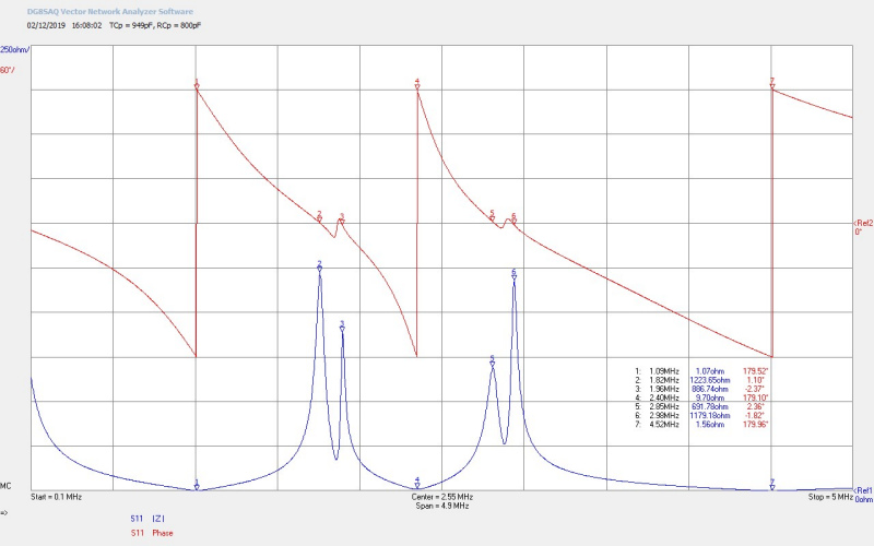
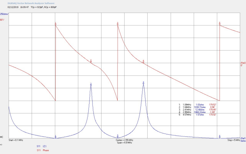
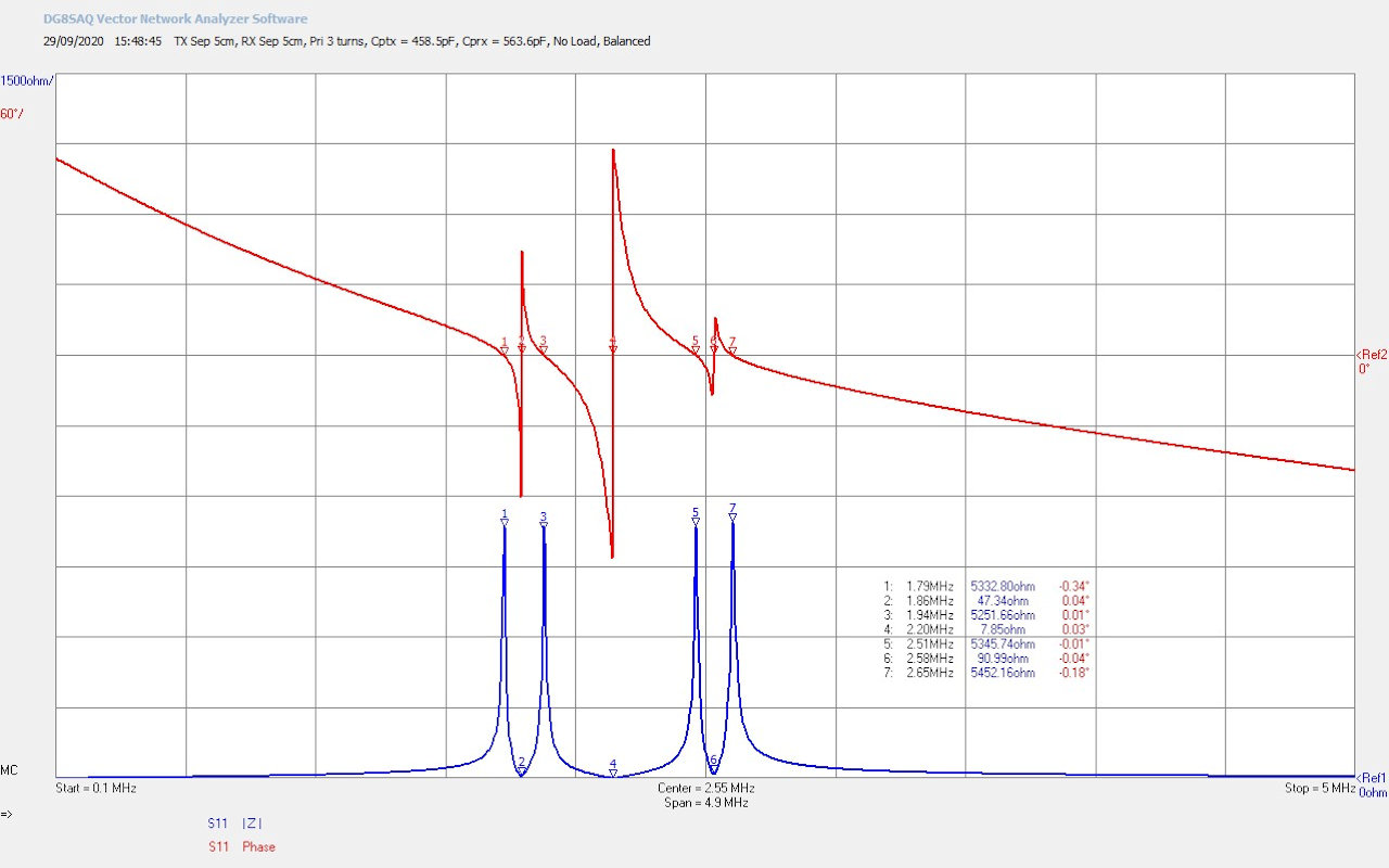
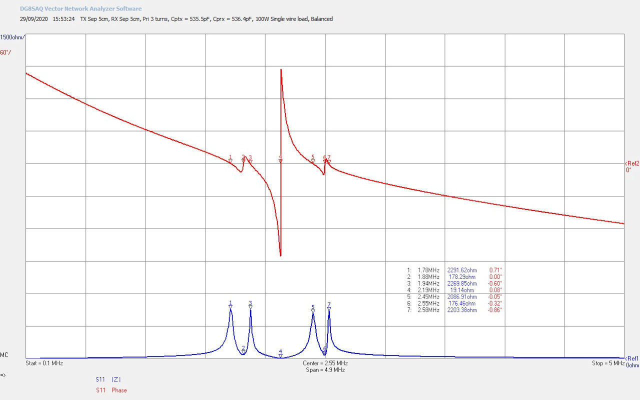
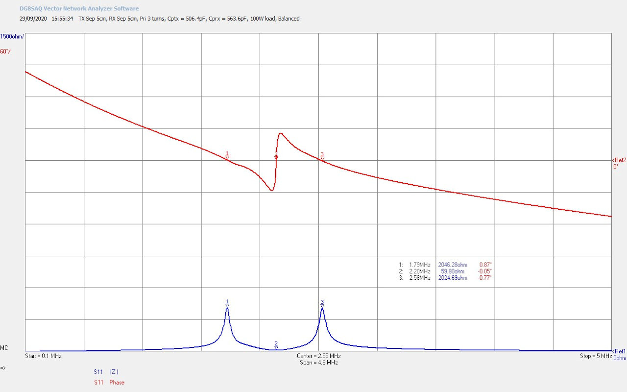
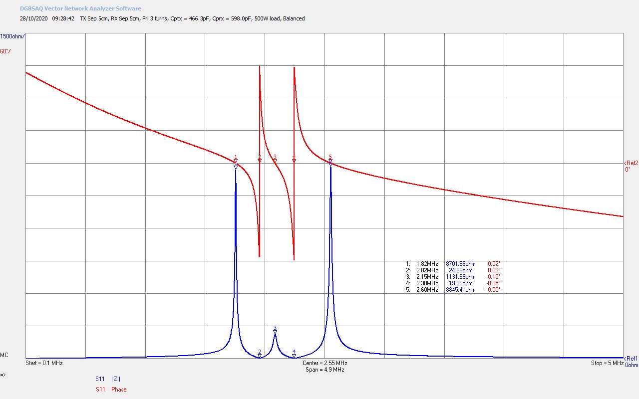
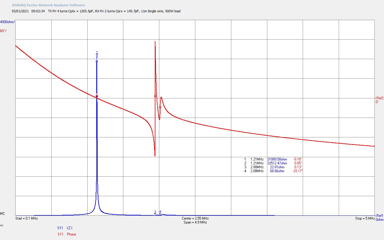
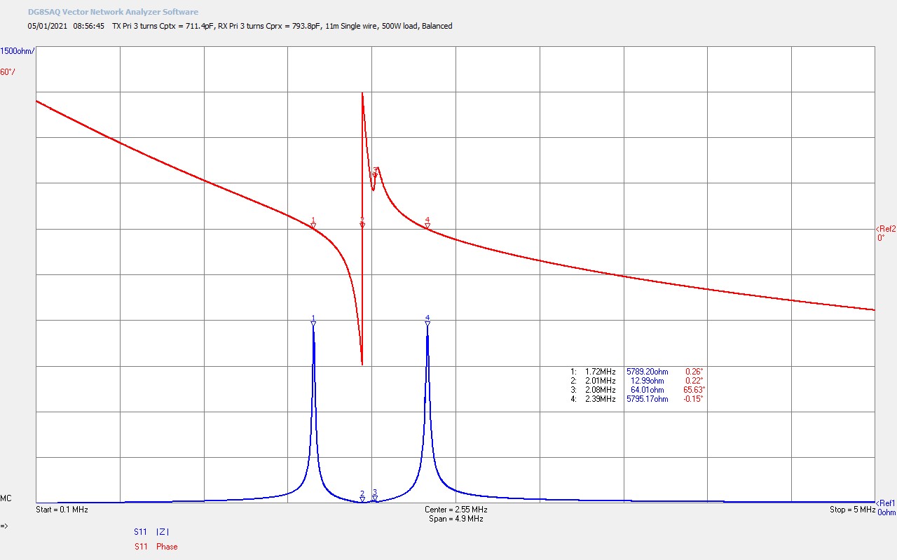
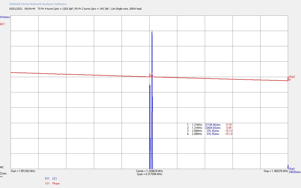
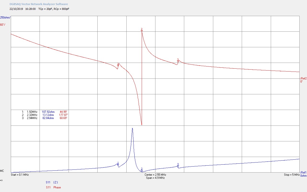
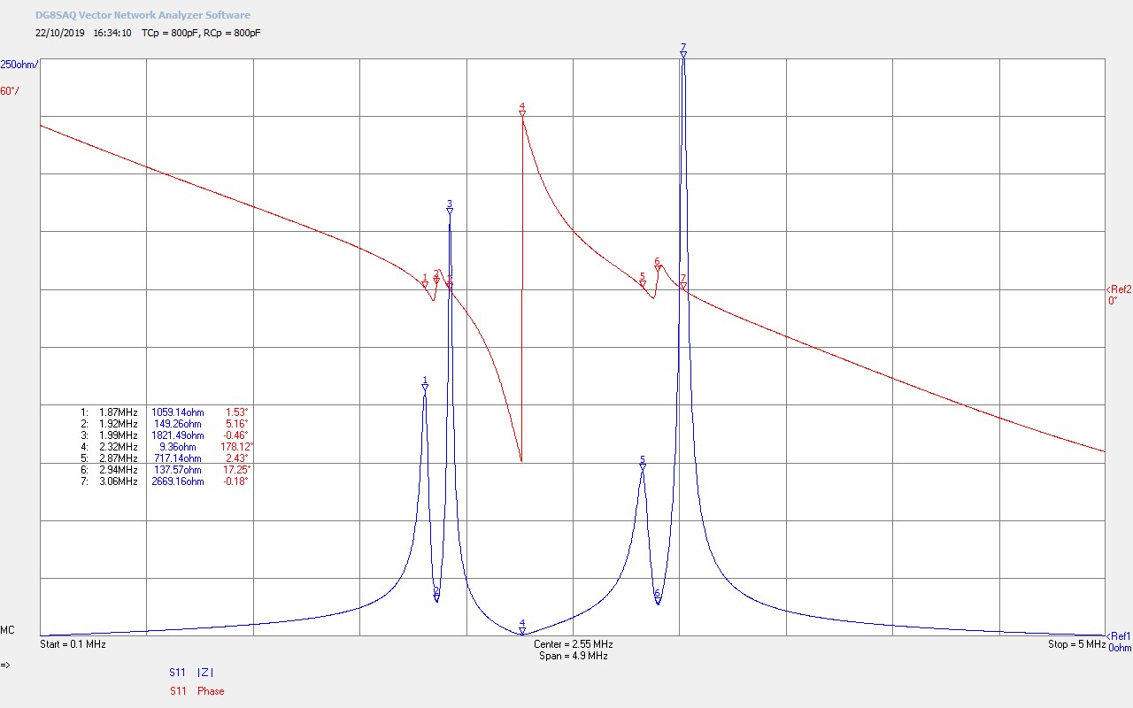
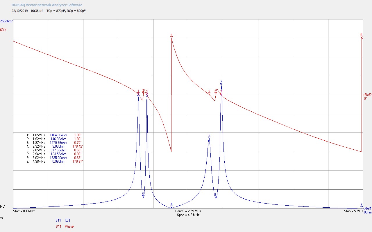
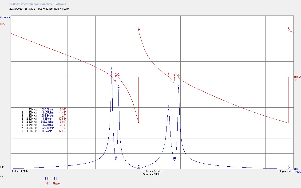
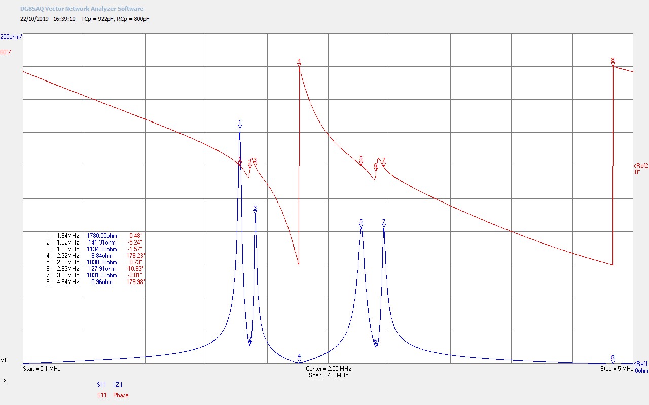
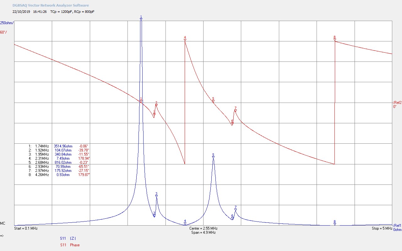
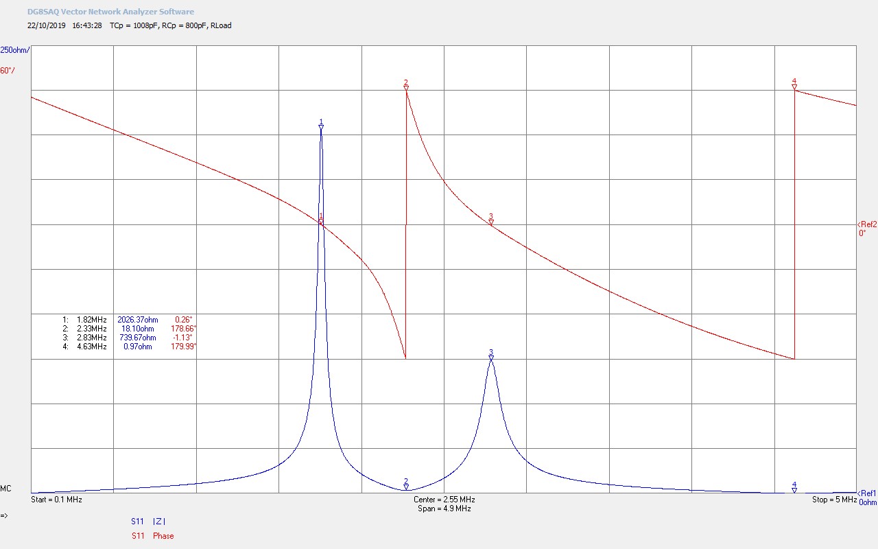
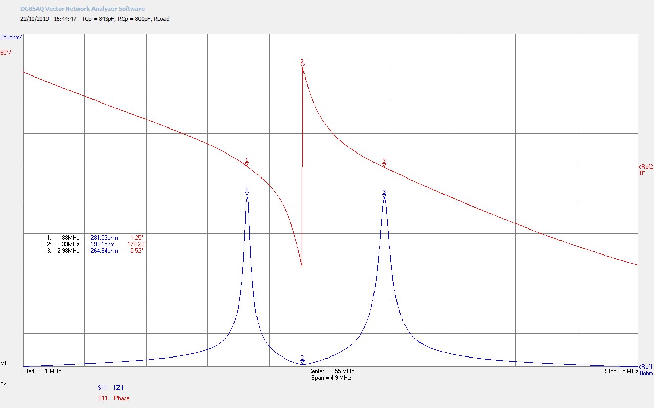
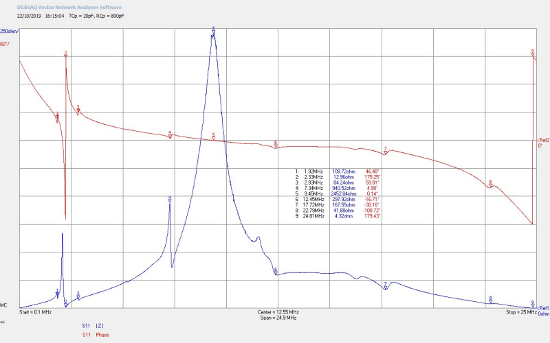
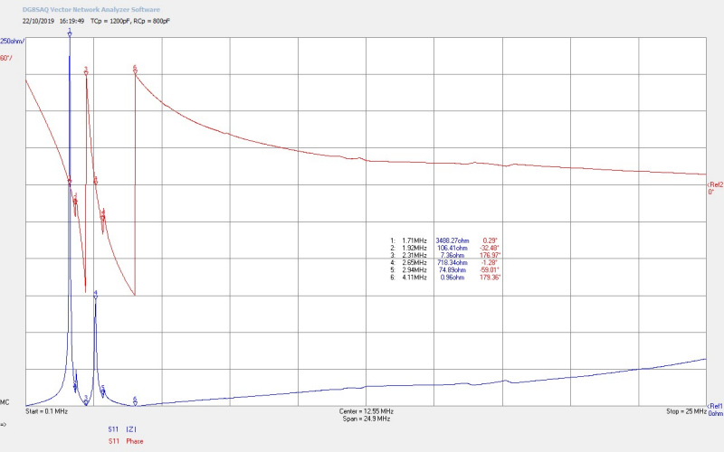
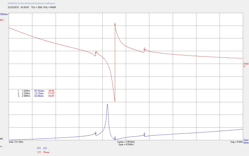
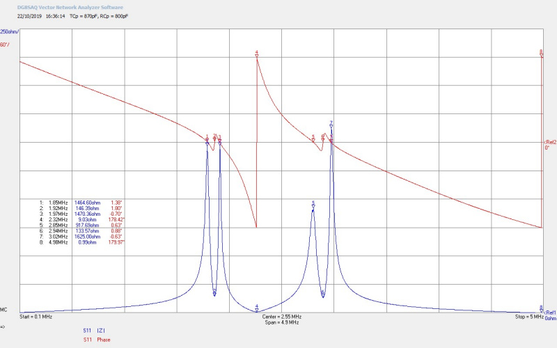
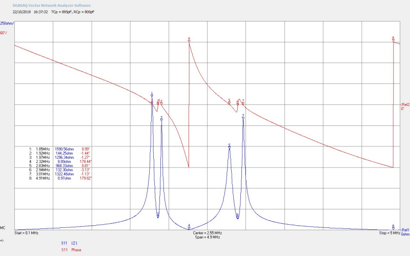
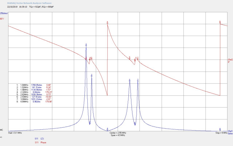
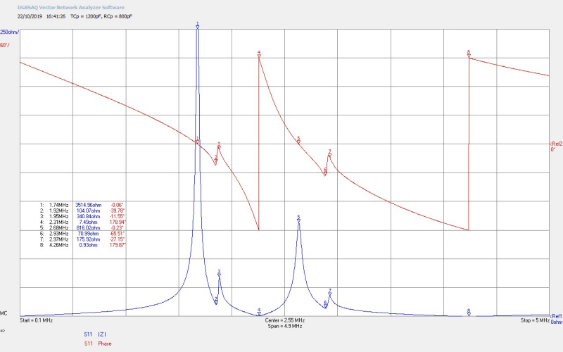
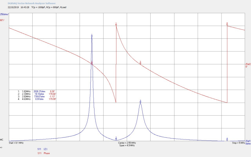
Figures 2 below show the detailed Z11 impedance measurements that were presented in the first video, and will be referred to in the consideration of the experimental results after the second video.

The second video demonstrates interesting phenomena and effects relating to the transference of electric power from the vacuum tube generator to the transmitter, and then via the single wire transmission medium through to the receiver coil, and to finally the load at the output of the receiver. Various different modes of transmission are considered which are established by different tuning points of the experiment.
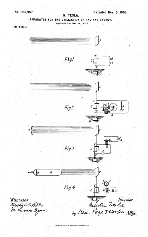
There have been a range of different interpretations as to the nature of wireless transmission of power from a resonant transmitter to a resonant receiver, through the surrounding medium, proposed as early as the late nineteen century by Maxwell[1], Tesla[2,3], Steinmetz[4] and much later by others such as Dollard et al.[5,6,7], Tucker et al. [8], and Leyh et al.[9]. Different sources have suggested different mechanisms for the transfer of power between transmitter and receiver, including the Longitudinal Magento-Dielectric mode, Multiple order magnetic field coupling, and Electric field coupling.
In my research into the transference of electric power so far, I have found most validity in both conceptual and experimental terms from wireless transmission at distances greater than that which can be attributed through near-field induction, (the conventional transformer effect), through the principle of the Longitudinal Magneto-Dielectric (LMD) mode. In my consideration of the results of the experiments presented in this post, I find the LMD principle to most closely account for the observed phenomena and properties surrounding the transfer of electric power through a near-field TMT arrangement.
I consider the experiments presented in this post to be transmission in the near-field, rather than what might ordinarily be considered by conventional antenna theory the mid-range, where the distance between the transmitter and receiver is more than 2-3 times the diameter of the coils, (antenna aperture). In this case the central tuned resonance of the TMT system is ~2Mc/s, which corresponds to a free-space wavelength of ~150m. Since the coils are connected by a single wire transmission line, and are spaced 1.5m apart, I very much consider this scenario to be near-field transmission since the receiver coil is very much less than a wavelength from the source.
The transfer of electric power in this scenario is as a result of the specific modes formed by the electric and magnetic fields of induction, and hence the transfer of power is “inducted” or “extended”, rather than propagated as would be the case for a transmitting antenna. In subsequent posts I will be presenting experiments on the telluric transfer of electric power where the wireless transmission distances are in the far-field, and are very much greater than the wavelength of the fundamental resonant frequency of the TMT system. Despite the near-field arrangement the transfer of electric power in this system is not via the conventional magnetic coupling of the “transformer effect”.
This was confirmed by removing the single wire transmission and simply terminating both bottom-ends of the secondary coils with a short wire extension, in order to lower the impedance at this end and ensure λ/4 resonation. In this condition, and when tuned over the full available frequency range, no transmission of power took place between the transmitter and receiver coils, even when both were tuned to the same resonant frequency at either the upper or lower frequency. If the conventional transformer effect occurred in the near-field then some detectable power would have been transferred between the generator and receiver load. This clearly shows that transference of electric power in this TMT experimental arrangement requires the transmission of the electric and magnetic fields of induction via a lower impedance path through the transmission medium, (in this case the single wire connection). When both of the short secondary extension wires were then subsequently connected to earth, (either independent dedicated rf grounds, or earth points from the utility supply), power was again transferred between the source and load at the correct tuning.
It is conjectured here that transference of electric power, at the correct point of tuning in this experiment, occurs through establishing the LMD mode of transmission as a standing wave between the transmitter and receiver coils, where a cavity is formed between the top-loads of the two secondary coils. In successive cycles of the generator oscillations electrical energy is coupled from the generator into the cavity. The pressure of the wavefront in the longitudinal mode moves backwards and forwards as it traverses the cavity from the transmitter to the receiver, reflected from the top load of the receiver and back again towards the transmitter where it is amplified or suppressed by coupling from subsequent cycles from the generator. Whether the longitudinal wavefront is amplified or suppressed depends on the tuning of the experiment and hence the longitudinal wavelength in the cavity.
At the correct point of tuning the amplitude of the wavefront is reinforced by successive cycles from the generator. The magnitude of this longitudinal wavefront reaches an equilibrium in the cavity based on the impedance characteristics of the cavity medium, its tuning, and dissipation of the stored power to both the transmission medium, and to the surrounding environment. The longitudinal wavelength within the medium is longer than that of the generator excitations, which represents a lower frequency of oscillation for the longitudinal mode. This puts the electric and magnetic fields of induction at different phase relationships throughout the length of the cavity, a property of the longitudinal mode that can measured in the cavity region, and is presented in the consideration of the experimental results below.
At the correct point of tuning the di-electric and magnetic fields of induction in the LMD mode form a standing wave in the cavity which results from the longitudinal wavelength, where the boundaries of the cavity are defined by the high impedance, high potential, points at the top-loads of the coils, and one or more null points form inside the cavity. At the fundamental frequency of the LMD mode, (not the same frequency as the fundamental resonance of the secondary coils or the generator oscillations), only a single null will exist in the centre of the cavity, and when the coils are closely spaced in the near-field. At higher order harmonics, and dependent on spacing between the coils multiple null points can form.
Each of the key experimental parts is now considered in more detail, and where appropriate based on the conjecture made above regarding the LMD mode of transmission:
Single wire transmission and the LMD mode
A key feature of the presented experiments in the transference of electric power between the transmitter and receiver is that power is transferred via a single wire which in itself is an unsusual method of transfer within standard electric circuit theory and experiment.
In a standard closed electric circuit current is continuous throughout the circuit with the voltage potential around the circuit dependent on the impedance of the elements and/or transmission lines that make up the circuit topology. The underlying premise is that a circuit has a forward and return path where the impedance is sufficiently low to allow for a “flow” of current from the source around the circuit, and returning to the source. Power is dissipated in the various impedances that make up the circuit according to their characteristics and the voltage and current phase relationship of the overall impedance of the circuit.
Ordinarily introducing a very high impedance, (in principle an infinite open-circuit), will reduce the current in the circuit to such a low-level, and in principle to zero, so that no current can flow around the circuit from and returning to the source, and hence no power is dissipated in that circuit. Even in an rf transmission line the normal transverse mode of transmission assumes a voltage and current distribution long the transmission line based on its distributed impedance, and its matching to the source and load terminations, where the transmission line is based on a closed circuit formed between the source and load in two or more conductive mediums between the source and load.
As can be seen in the videos the four incandescent load can be fully lit where no obvious closed circuit exists. The load is not connected between the outputs of the secondary (topload and base of the secondary), but is rather only connected via the base of a secondary. The other side of the load is left as open-circuit with a short trailing wire. Once again a cavity is formed between the top-load of the transmitter secondary and the open-circuit of the trailing wire, which would enable the LMD mode to establish. The electric and magnetic fields of induction are both present around the boundaries of the single wire, and a longitudinal wavefront is established at the longitudinal frequency in the cavity. At the upper and lower resonant frequency of the secondary energy is coupled from the generator into the cavity, and the longitudinal mode is established along the length of the cavity.
A higher impedance load placed within the electrical cavity at resonance will dissipate power in a transverse mode from the established wavefront when the electric and magnetic fields of induction local to the load are in phase. That is, the induced voltage across the load, and the induced current in the load, are predominantly in phase in the region of the load. In this case energy can then be transferred (induced) from the longitudinal wavefront to the transverse mode, and power will be dissipated in the lamp as both light and heat with a warm yellow colour temperature, as can be seen in the video. Placing the load right at the end of the wire will not light the incandescent lamp at the termination of the cavity, where the voltage and currents induced in the wire are 90° out of phase at the open-circuit termination.
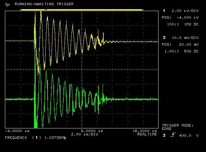
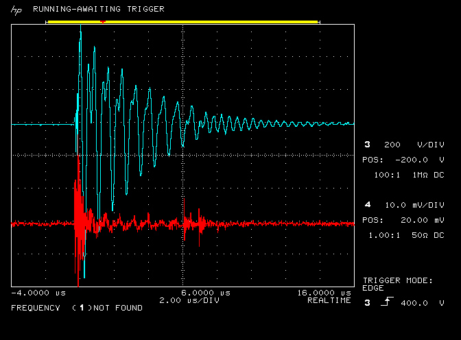
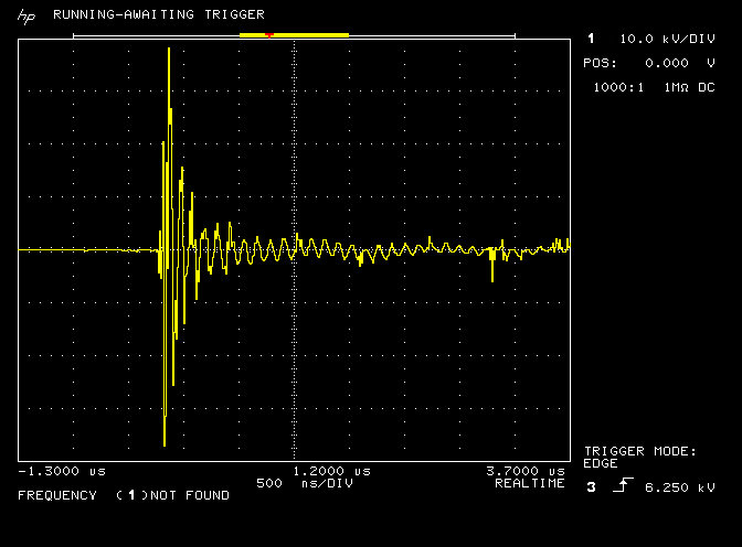
Figures 3 below shows the phase relationship between the voltage and current oscillations of the generator in the primary, and the phase relationship between the voltage and the current at three different points in the single wire section of the cavity. It is conjectured that the changing phase relationship between the induced voltage and currents along the single wire is characteristic of the longitudinal mode established in the cavity, and results in unusual electrical phenomena and characteristics that are measured in TMT experimental systems.
In each figure the traces are as follows:,
Yellow – The voltage across the transmitter primary.
Green – The current through the transmitter primary, calibrated 1A/div.
Cyan – The voltage measured at centre of the single wire transmission line.
Red – The current measured through the single wire transmission line, calibrated 1A/div.
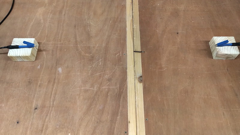
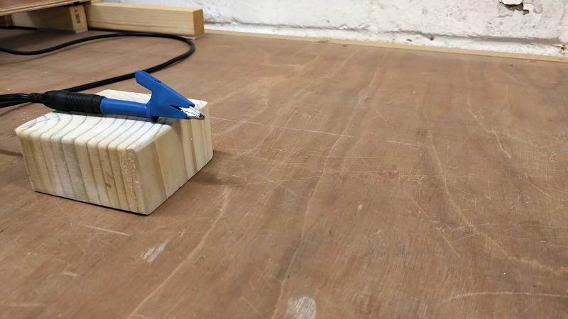
Each frequency 1.75, 1.94, and 3.32 Mc/s are measured at three different points in the single wire section of the cavity:
SWC1 – At the bottom-end of the transmitter secondary.
SWC2 – In the middle of the single wire.
SWC3 – At the bottom-end of the receiver secondary.
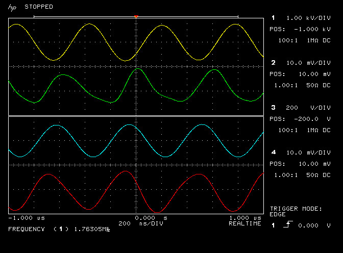

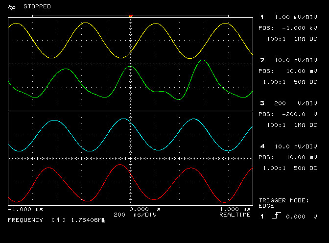


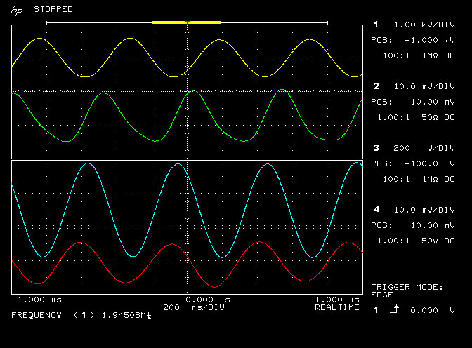
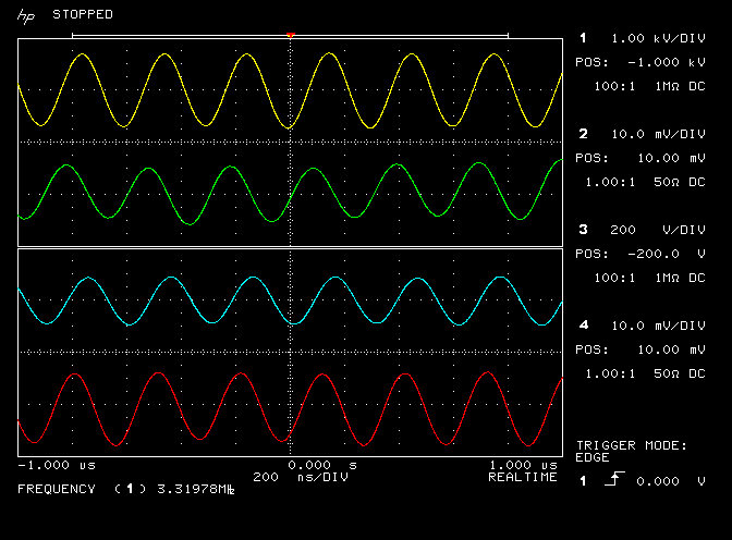

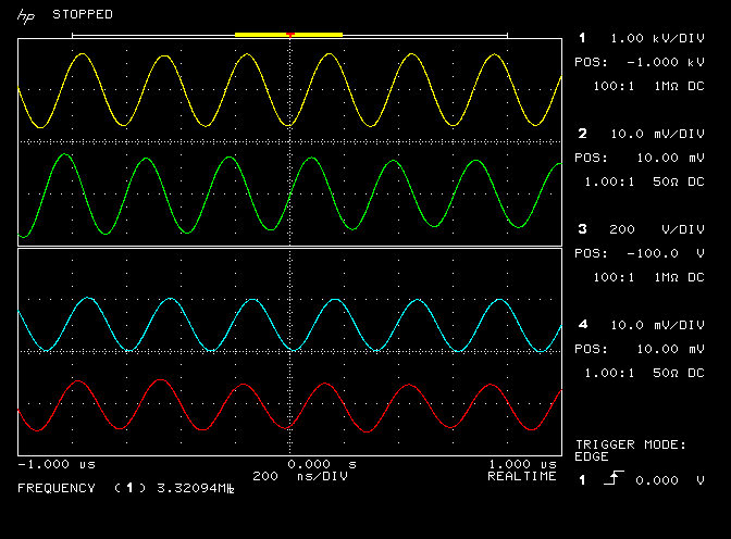


It is important to note from these measurements the varying change in phase relationship between the voltage and current at the transmitter, centre, and receiver ends of the single wire, (cyan and red trace), for tuned power in the receiver load, figures 3.4, 3.5, and 3.6. It is conjectured that this varying phase change across the single wire length between the voltage and the current, (~1.94Mc/s), which is hardly present when not correctly tuned for the transference of electric power (~1.75Mc/s and 3.32Mc/s), is indicative of a standing wave resonance of the LMD mode in the cavity, a cavity which has been formed by two coils that are matched at resonance in the TEM mode, and joined by a transmission medium. It is the combination of matched resonance in the TEM mode at the coils, and a tuned standing wave of the LMD mode that leads to the transference of electric power with very low loss between the generator and the final receiver load.
Tuning to power a load within the single wire transmission line
This experimental point is shown in figures 1.1 and figures 2.4, 2.7-2.9. Interestingly this condition is little different to the open-circuit terminated single wire case discussed above. However, now both transmitter and receiver are connected together via the single wire transmission line which also contains an incandescent lamp load. The single wire lamps could be tuned to light fully at either the lower or upper resonant frequencies of the combined secondary coils, with no or very little power dissipated in the final load at the receiver primary.
Once again a cavity is formed between the two top-loads of the transmitter and receiver secondaries, and through the single wire transmission line, the LMD mode is present, and there is a varying phase relationship between the voltage and current measured in the single wire. The mis-match in tuning between the transmitter and receiver means that, whilst the LMD mode is always present, it is not tuned to form a standing wave in the cavity. There are no detectable null points along the single wire and the neon lamp at the top-load of the receiver is not lit, showing that there is no high-potential at the top-end of the receiver coil. In this case the TMT transmission system is not tuned between the transmitter and receiver and so no power is being coupled through the receiver coil to its load. The system appears almost identical to the open-circuit single wire case above.
Energy is being coupled at the secondary resonant frequency from the generator into the transmitter secondary in the transverse mode, and the mis-match in tuning between the high-Q transmitter and receiver means that energy is not reaching the receiver coil but rather being consumed in the load in the single wire. This is further demonstrated in the video when the receiver secondary is unplugged from the single wire the lamps of the load in the single wire stay lit, they do change intensity slightly as the tuning changes, but can be returned back to full brightness by slight adjustment at the transmitter primary capacitor.
In summary, the transference of electric power from the generator to the single wire load occurs at the lower or upper resonant frequency of the transmitter coil, and is largely independent of the mis-matched termination at the other end of the single wire, whether that be a simple open-circuit, or short-circuit to ground, or another mis-matched resonant circuit such as a TMT receiver.
Tuning to power a load at the output of the receiver
This experimental point is shown in figures 1.2 and figures 2.5, and 2.6. With careful tuning there is a very narrow band, as seen on the video, where the high-Q TMT transmitter and receiver are tuned very accurately to one another, and power can be transferred directly between the transmitter and receiver via the single wire transmission, and with very little power dissipated in the single wire or its load. In this experimental setup the tuned frequency at the generator is between ~1.92 – 2.05 Mc/s to demonstrate the transference of electric power between generator and final load.
In this scenario the LMD mode is tuned in the cavity to form a standing wave, a null point is present at the centre of the path length of the cavity, which in this experiment where the single wire load was placed. Both top-loads are at maximum potential indicating that the cavity is in the fundamental resonant frequency of the LMD mode, that is nλLMD/2, where n=1 and there is a high potential point at the transmitter top-load, a zero potential null point in the single wire, (at the single wire load), and a high potential point at the receiver top-load.
Overall this is now the special condition where firstly, the transverse electromagnetic mode (TEM) is matched independently for both the transmitter and receiver coils, so they are both able to couple maximum energy, the transmitter from the generator, and the receiver to its load, at the same resonant frequency. This is secondly combined with the LMD mode formed in the secondary coil of the transmitter TMT, and tuned within the cavity of the single wire transmission medium to form a standing wave, where in its fundamental mode a single null point exists in the centre of the single wire transmission medium. The combination of the TEM and LMD modes both correctly tuned, leads to an inter-dependent balanced condition within the electrical system, where transference of electric power between the generator and load can occur with minimal loss.
In principle, transmission in this mode could cover great distances where an LMD standing wave is established in a transmission cavity where there are many null points along the single medium of the conductor, whether that be a wire, the earth, or other lower impedance or resonant medium. Again in principle with the correct setup of the TEM and LMD modes in the complete system very little power need be lost in the transmission medium, which can be tuned correctly by detecting the null points in the medium, and the varying phase relationship of the measured voltages and currents in the medium, which appears at this stage to be an indication of the LMD mode.
Summary of the results and conclusions so far:
1. In consideration of the experimental results presented and phenomena observed, it is conjectured that the LMD mode is established in a resonating coil when a cavity is formed between the top-load of the coil, in this case an open-circuit with a neon indicator bulb, and the outer boundary point of the circuit connected to the bottom-end of the coil. The LMD mode enables transmission of the electric and magnetic fields of induction together around the boundary of the single transmission medium, in this case around the outside of the single wire. The magnetic and di-electric fields of the LMD mode are in the same plane of travel and hence constitute a longitudinal pressure wavefront that traverses the cavity reflecting from the high impedance boundaries at each end and establishing an LMD wave with wavelength distinct from the transverse resonant wavelength of the transmitter and receiver secondary coils.
2. When the LMD mode is not established as a standing wave within the cavity of the single transmission medium the energy coupled from the generator into the transmitter coil by transverse induction is consumed by a higher impedance load in the single transmission medium, or with inadequate load in the transmission medium will be discharged to the surrounding environment through streamers at the high potential top-load.
3. When an LMD standing wave is established in the cavity, and the high-Q transmitter and receiver coils are both resonating in equilibrium with each other in the very narrow matched band (~1.92Mc/s – 2.05Mc/s) power is transferred directly from the generator to the final load at the receiver, with very little energy consumed in the single transmission medium
4. An LMD standing wave can be established in a cavity that is geometrically and electrically reciprocal at each end, e.g. with an identical TMT transmitter and receiver designed to resonate at the same transverse frequency, which causes the longitudinal pressure wave to be reflected from each end of the cavity.
5. Where the wavelength of the LMD mode is a whole number of half-wavelengths nλLMD/2, amplification of the LMD mode will occur in the transmitter until a dynamic equilibrium is established within the electrical system and with the surrounding medium. In this case the null point/s of the standing wave can be measured in the single transmission medium, and tuned carefully either side of this point will show the null point to move towards either end of the single transmission medium, before collapse of the standing wave at the coil boundaries.
6. The LMD standing wave mode could be indicated by a varying phase change between the voltage and current waveforms measured along the length of the transmission medium. It is conjectured that this phase change is preliminary evidence of the amplified longitudinal mode established in the cavity.
7. The combination of the TEM and LMD modes both correctly tuned, leads to an inter-dependent balanced condition within the electrical system, where transference of electric power between the generator and load can occur with minimal loss.
The preliminary results for the transference of electric power in the near-field indicate that considerable more study is required on the various transmission modes present in the TMT system, and particularly a more detailed measurement and study of the phase relationships of the electric and magnetic fields of induction in the transmission medium, and the difference in the resonant wavelengths of the transverse and the longitudinal modes. These two modes appear to interact constructively and in an inter-dependent way when tuned for the optimal transference of electric power between the generator and the receiver load.
Click here to continue to part 2 on the transference of electric power, where the experiment is powered by a spark gap generator, and the differences explored and contrasted to the results obtained here with a single frequency feedback oscillator.
1. Maxwell, J., A Dynamical Theory of the Electromagnetic Field, Phil. Trans. Royal Society, pg459-pg512, January 1865.
2. Tesla, N., System of transmission of electrical energy, US Patent US645576A, March 20, 1900.
3. Tesla, N., Colorado Springs Notes 1899-1900, Nikola Tesla Museum Beograd, 1978.
4. Steinmetz, C., Elementary Lectures on Electric Discharges, Waves and Impulses, and Other Transients, McGraw-Hill Publication, 1911.
5. Dollard, E., Condensed Intro to Tesla Transformers, Borderland Sciences Publication, 1986.
6. Dollard, E. & Lindemann, P. & Brown, T., Tesla’s Longitudinal Electricity, Borderland Sciences Video, 1987.
7. Dollard, E. and Energetic Forum Members, Energetic Forum, 2008 onwards.
8. Tucker, C. & Warwick, K. & Holderbaum, W., A Contribution to the Wireless Transmission of Power, Electrical Power and Energy Systems 47 p235-242, 2013.
9. Leyh, G. & Kennan, M., Efficient Wireless Transmission of Power Using Resonators with Coupled Electric Fields, Nevada Lightning Laboratory, 40th North American Power Symposium, 2008.