The vacuum tube generator (VTG) mainly used for experiments in the displacement and transference of electric power is based around a pair of 811A power triode vacuum tubes, of either RCA or Russian origin, and with electrical characteristics generally as defined in the RCA 811A datasheet. The 811A’s have demonstrated to be highly flexible, with high reliability, and good overall medium power performance, versus cost and availability, when used in a variety of different configurations. The final output of this generator with these tubes can provide a maximum sustained RF output power of ~600W, and peak output for short bursts (up to 10s) of 900W, and over a wide frequency band up to ~5Mc/s. In addition, the design and implementation of this generator has been arranged in such a way that it can be used in a variety of different configurations, including:
1. A tuned plate class-C Armstrong oscillator which derives automatic feedback from a pick-up coil placed close to the secondary coil.
2. A variable frequency Hartley power oscillator when combined with an independent oscillator drive module.
3. The output stage of a linear power amplifier, when fed with a suitable drive waveform in grounded grid, grid biased, or cathode follower configurations.
4. A modulator stage with suitable cathode keying via a mechanical or semiconductor switching circuit.
5. CW, burst, and modulated oscillation modes when used with or without a dc smoothing capacitor in the plate HV supply.
Other VTGs using the RCA 833A/C and Eimac 4-400A/C are more suited to higher power experiments including, telluric transmission and strong non-linear impulses for displacement experiments, and will be reported in subsequent posts.
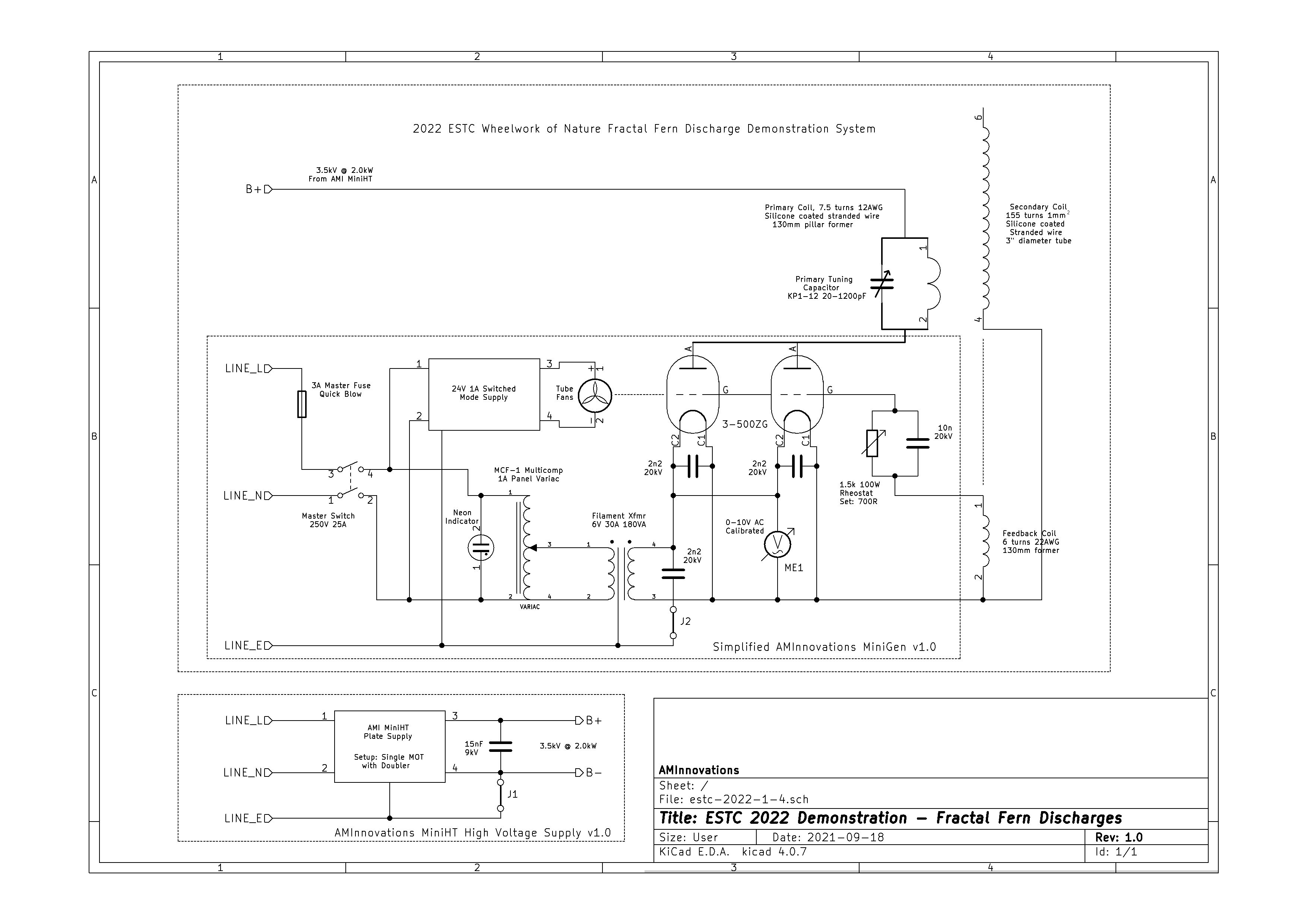
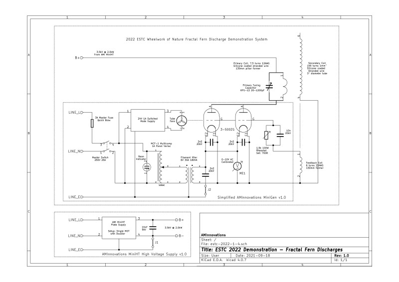
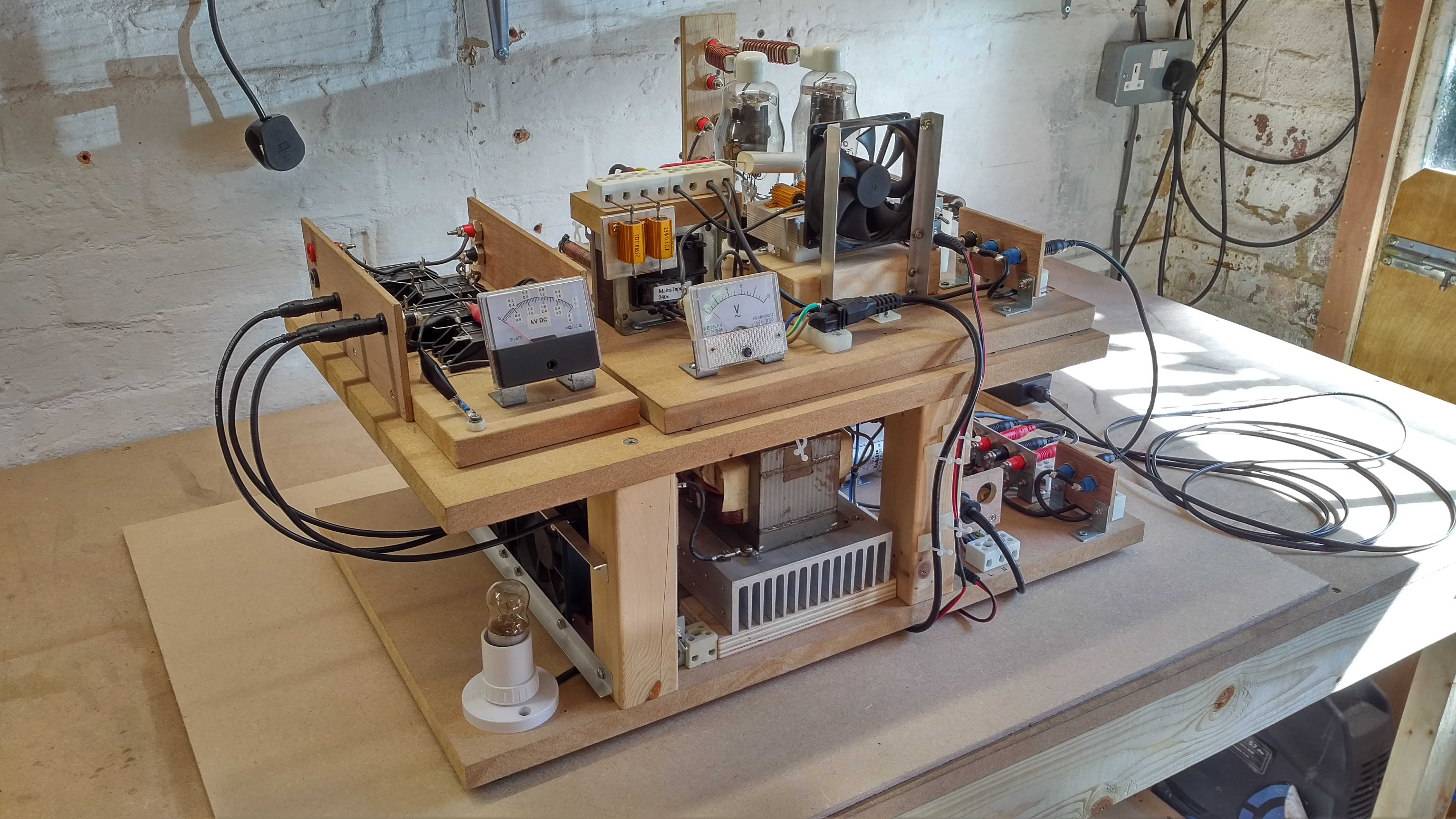
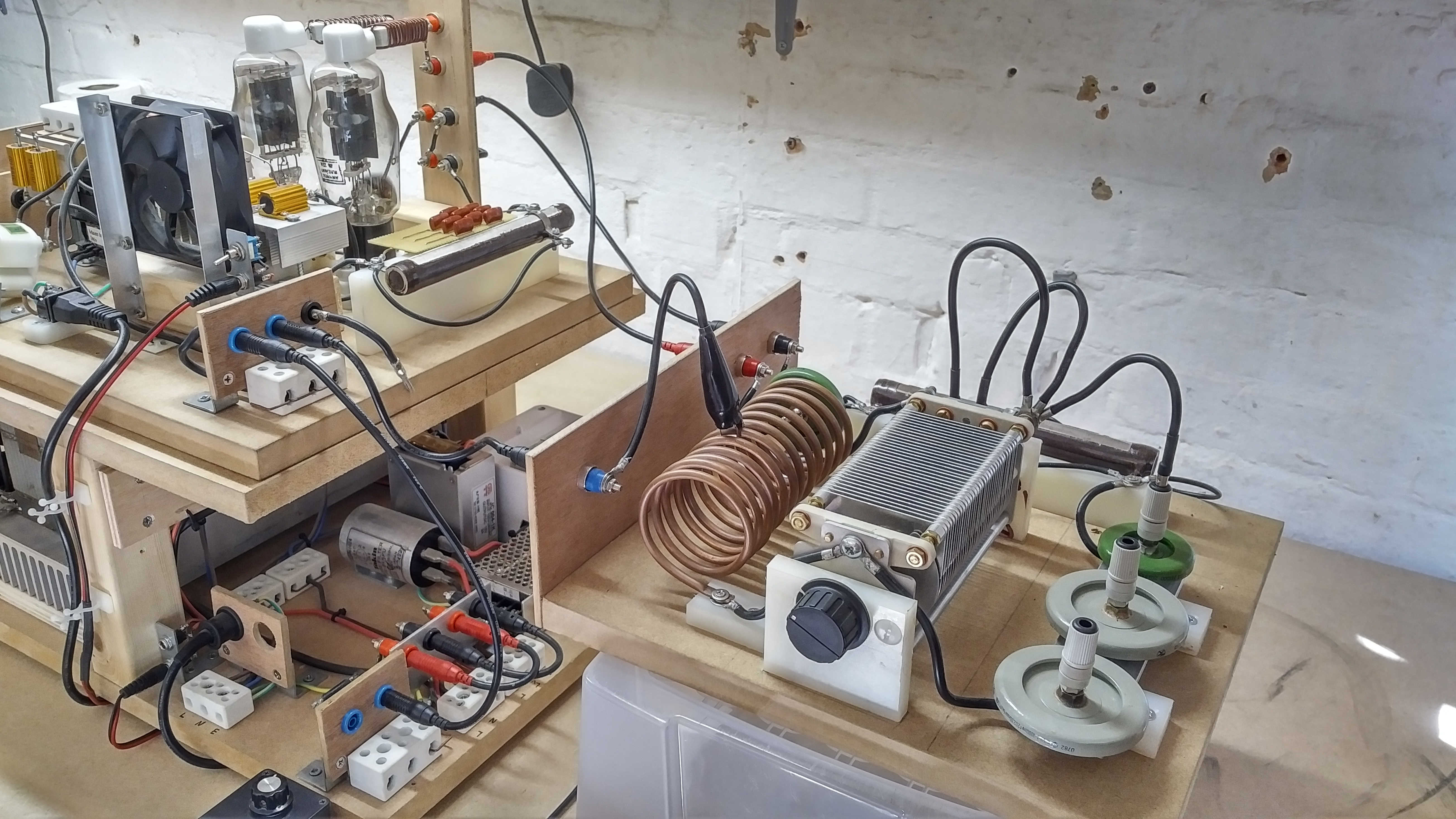
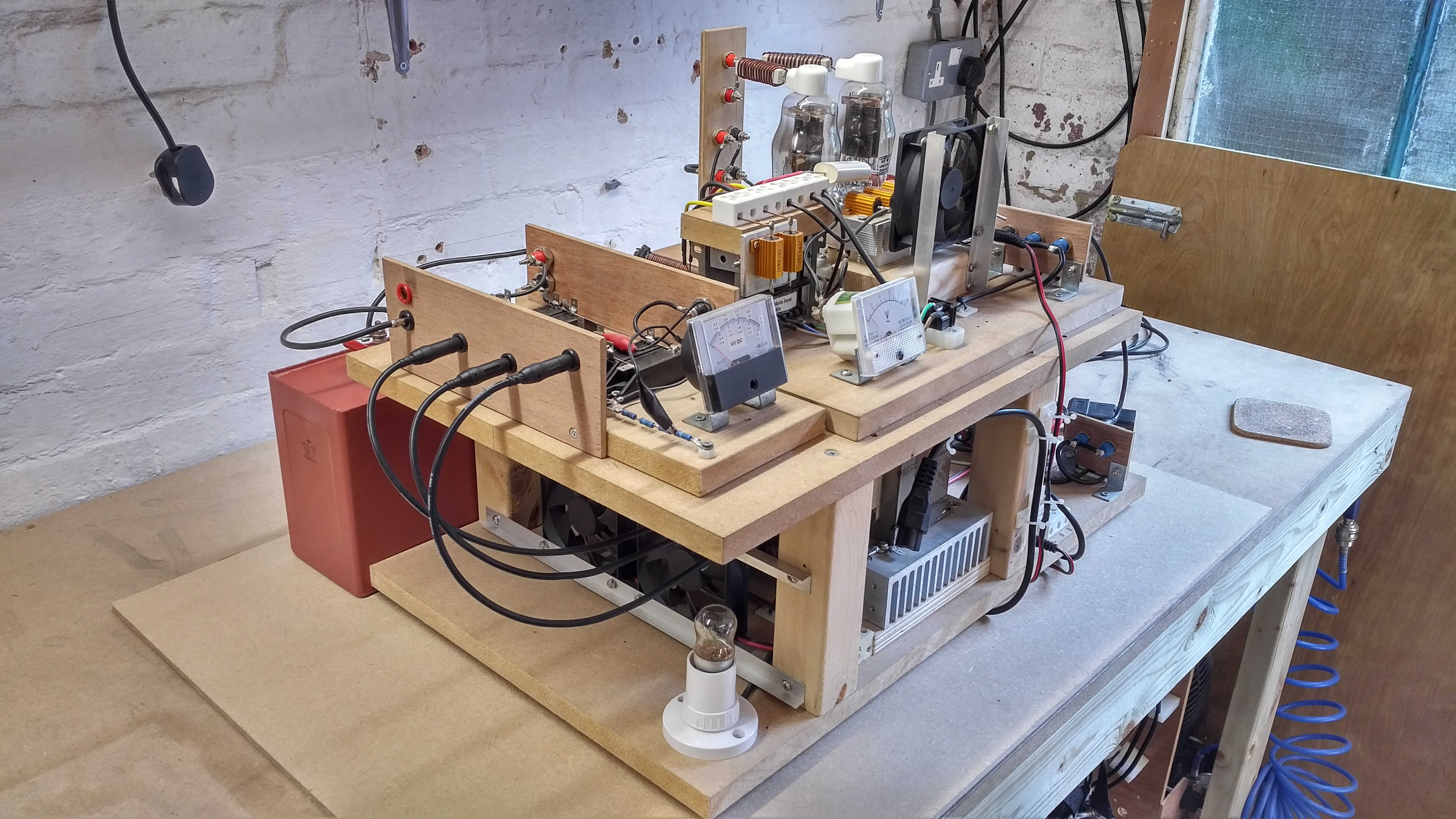
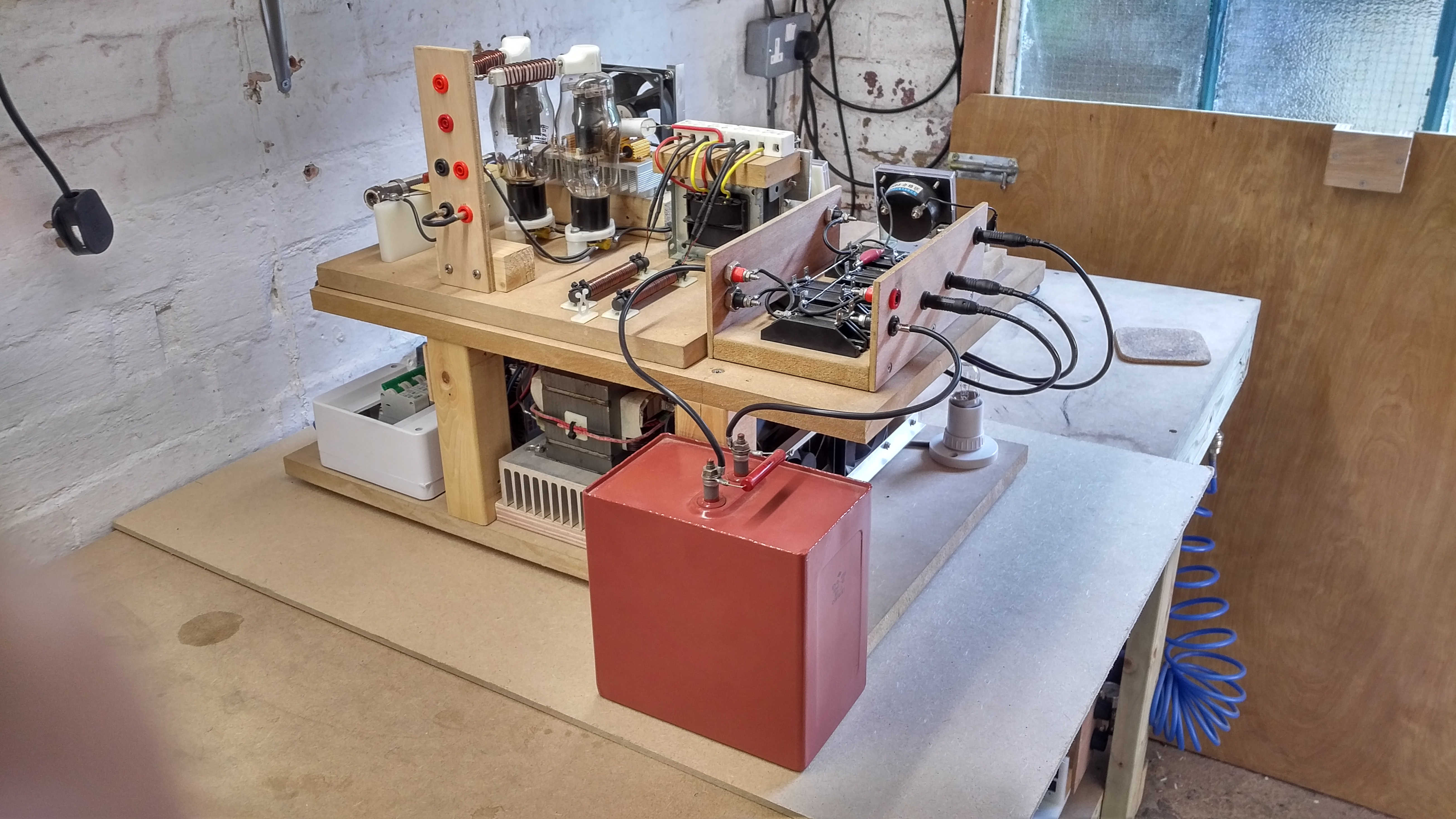
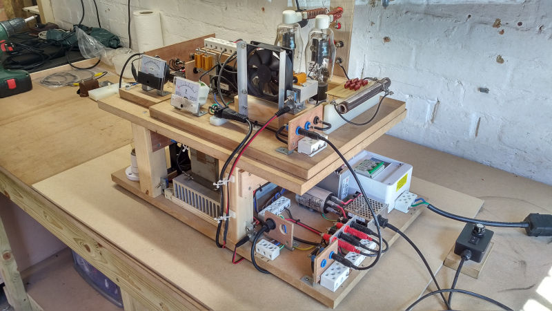
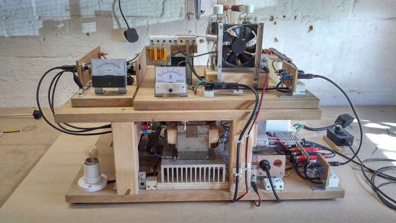
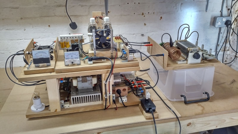
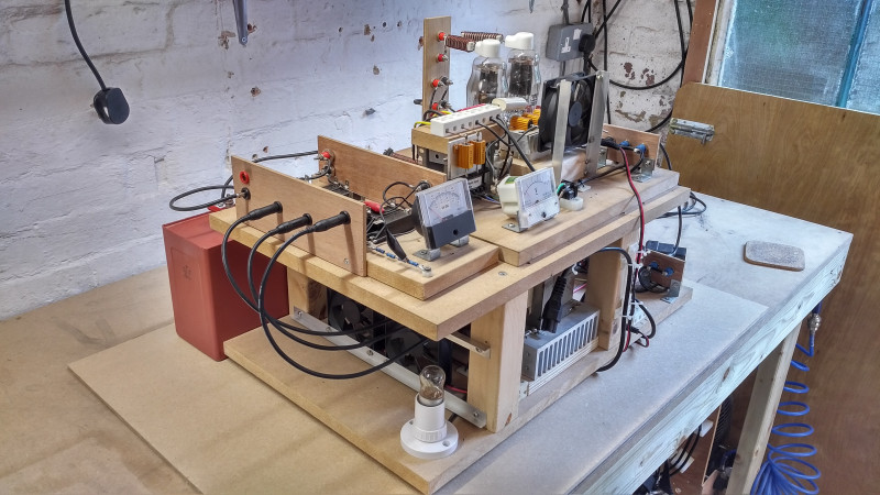
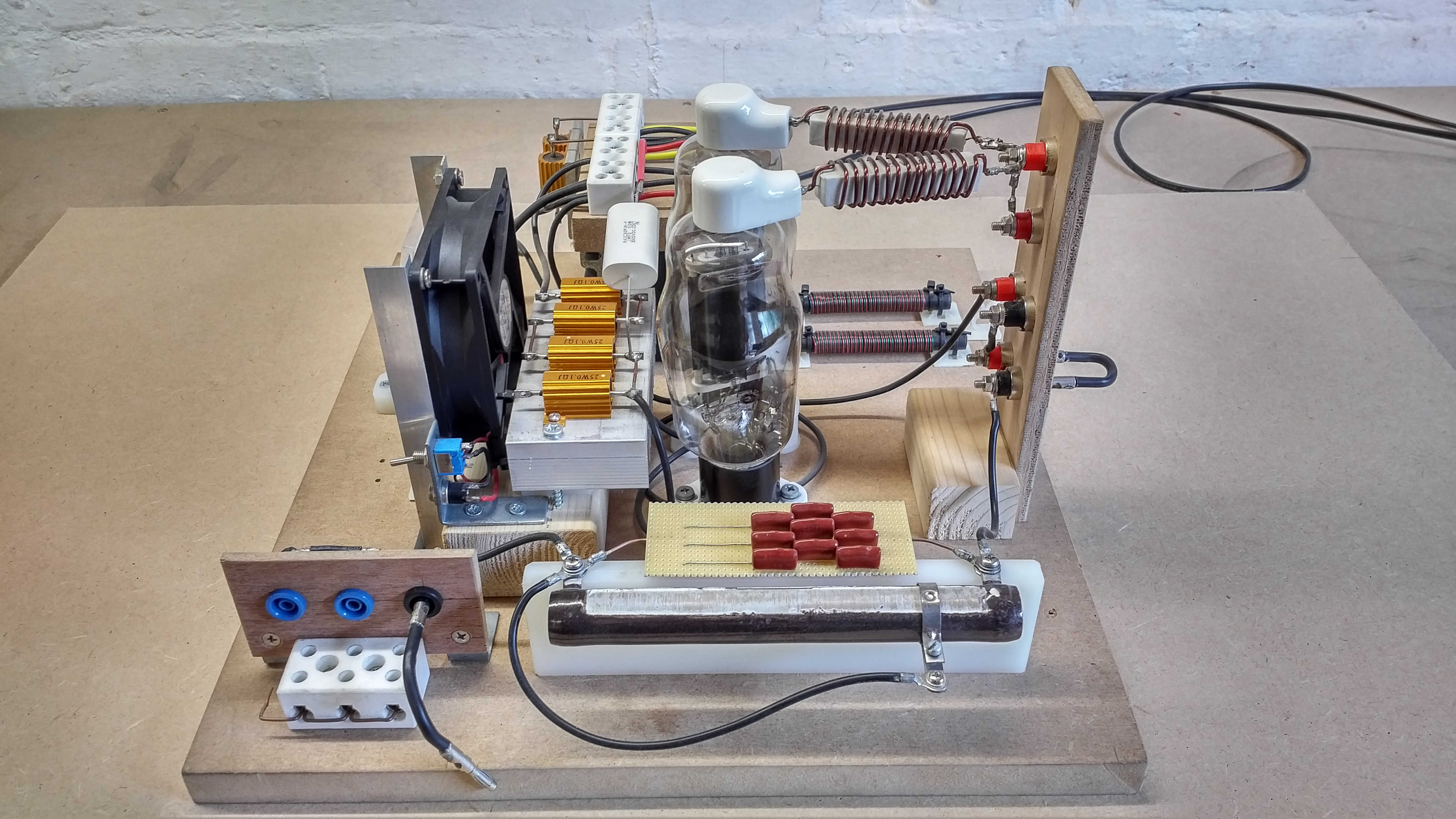
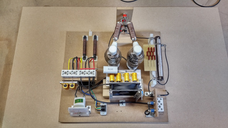
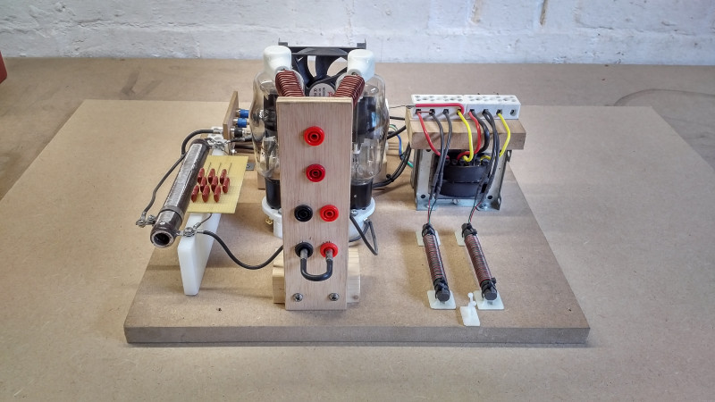
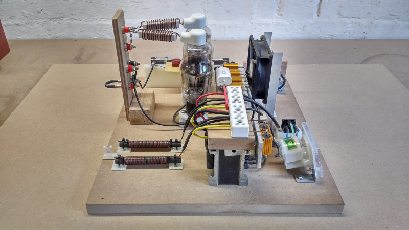
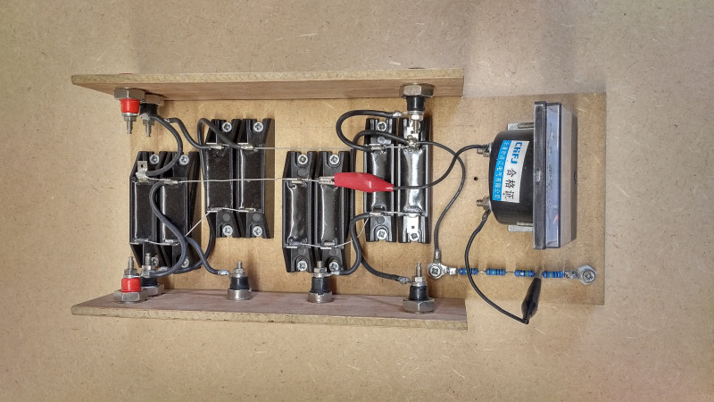
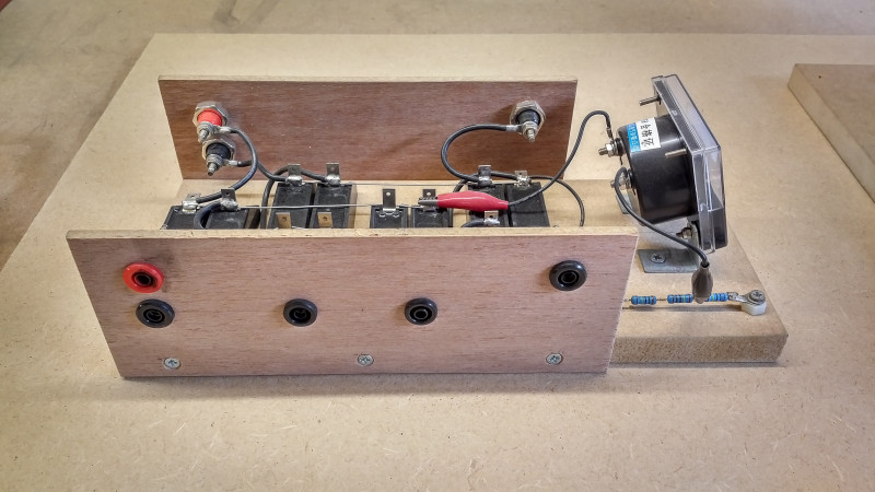
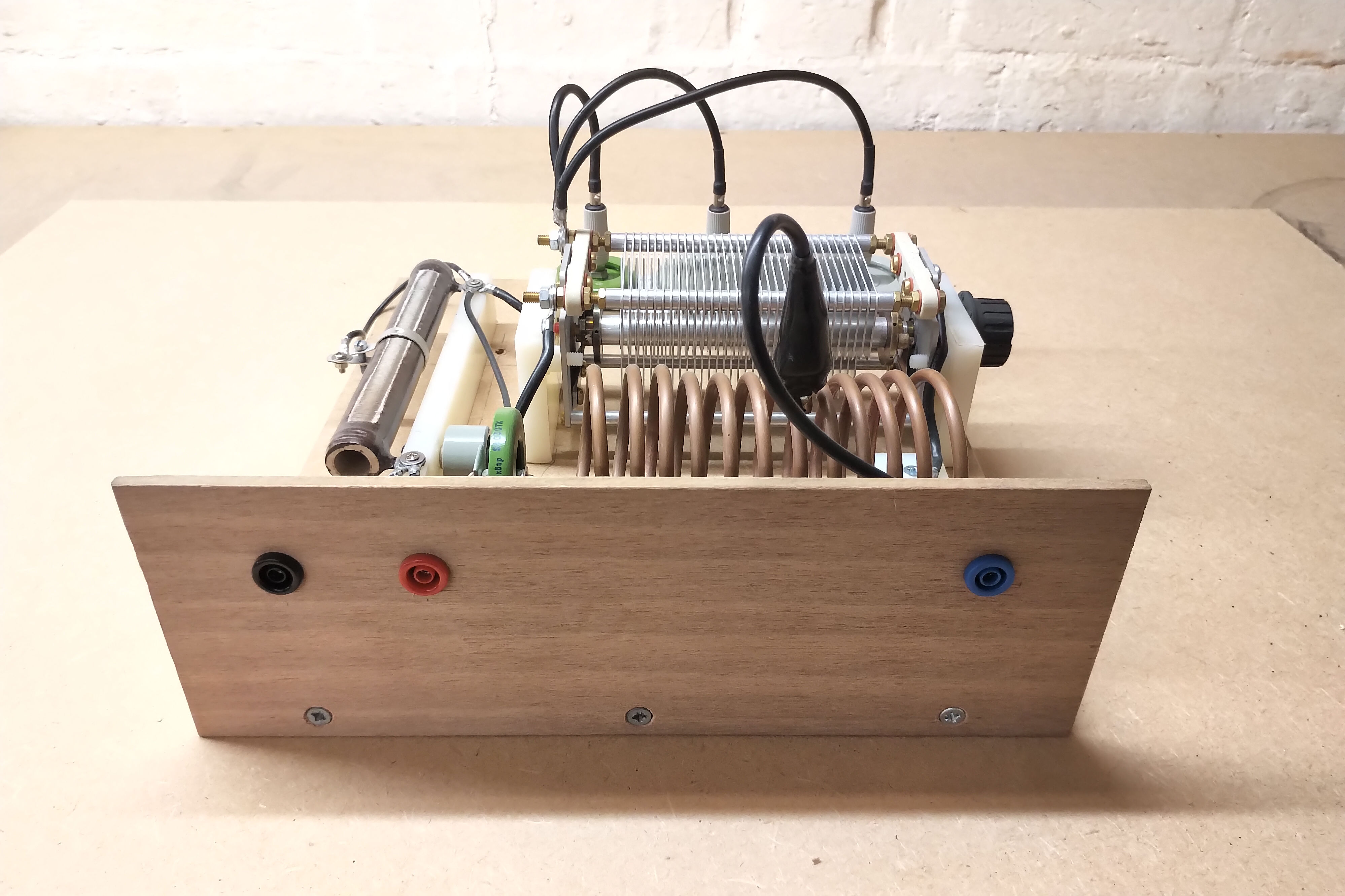
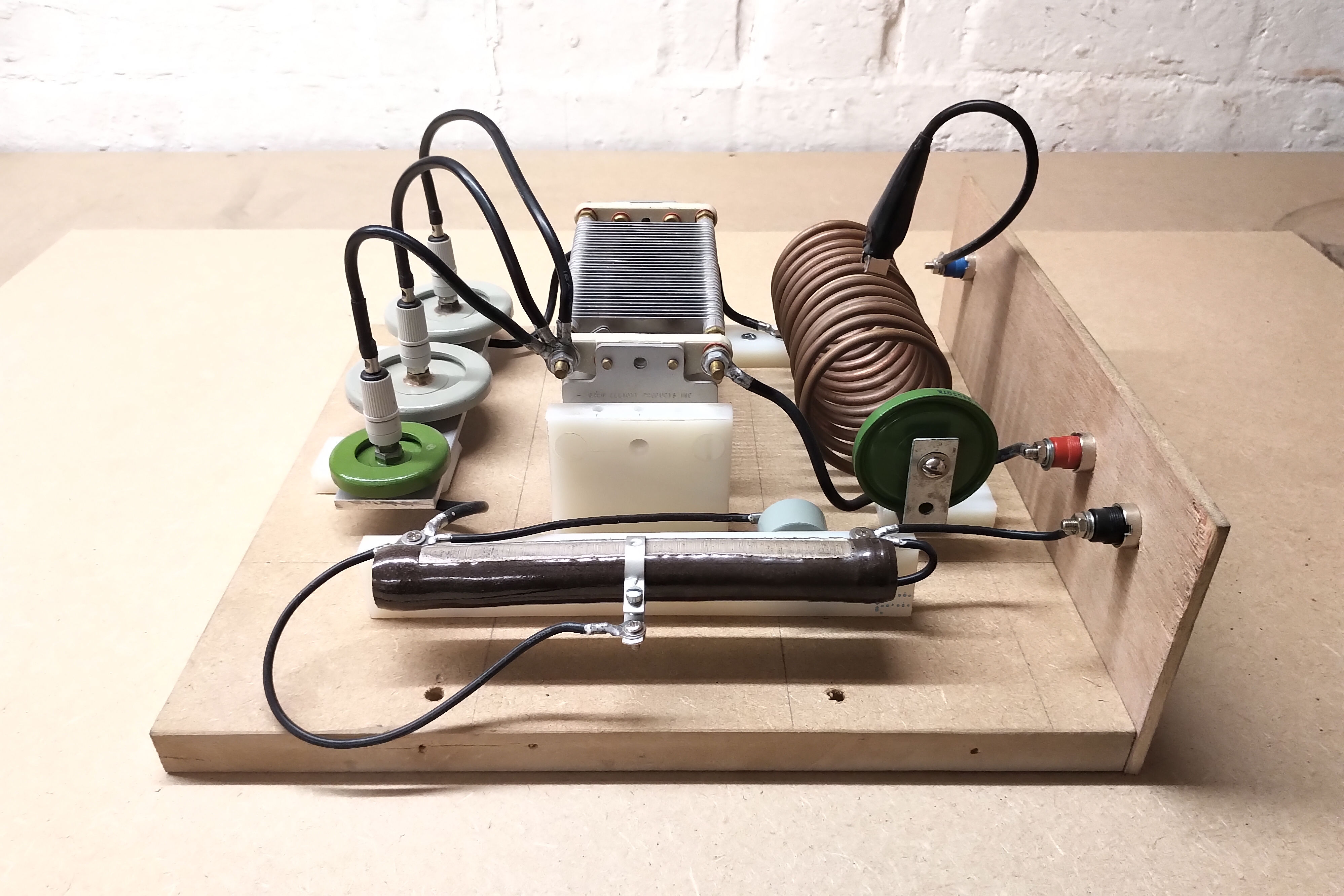
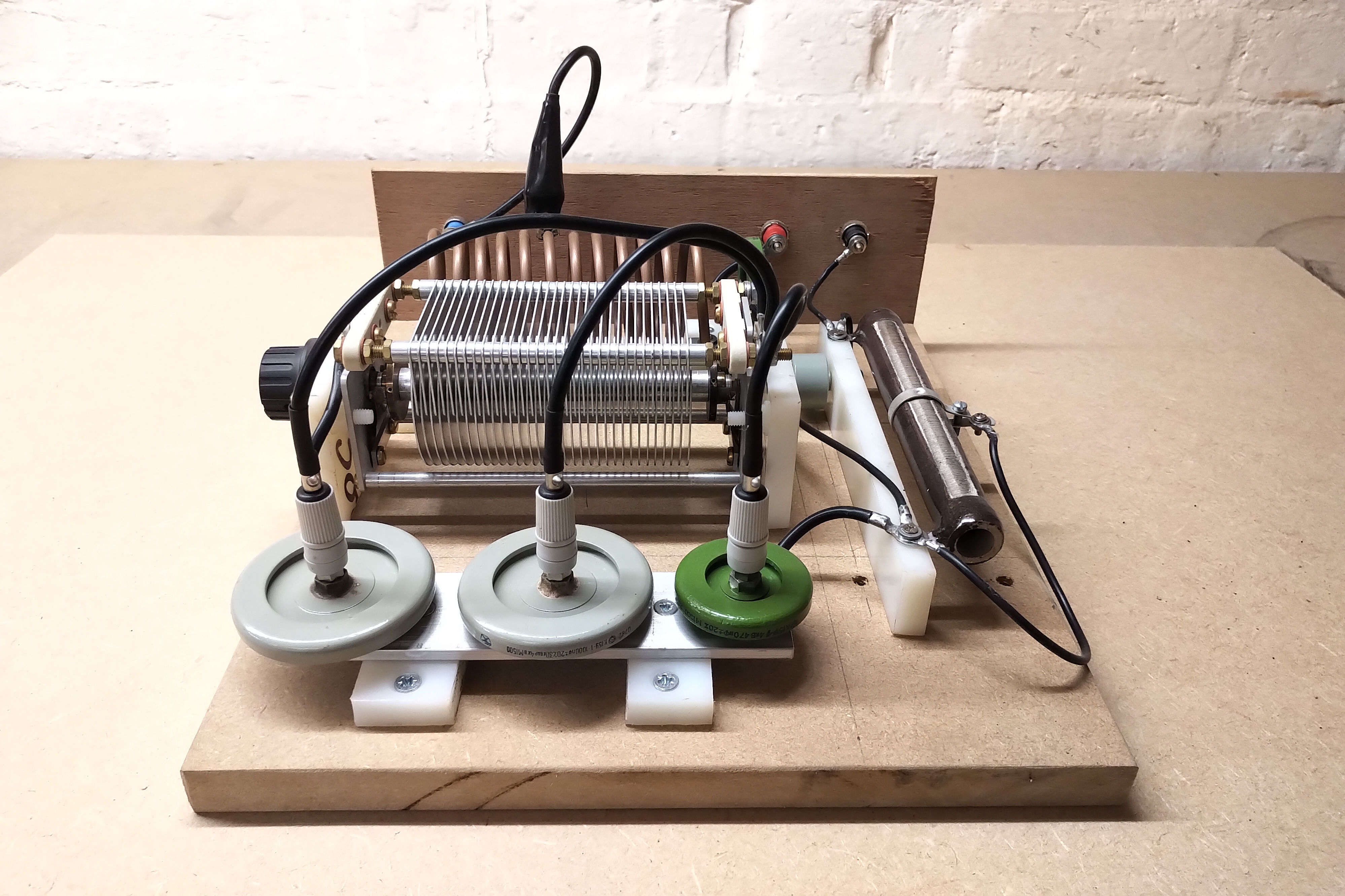
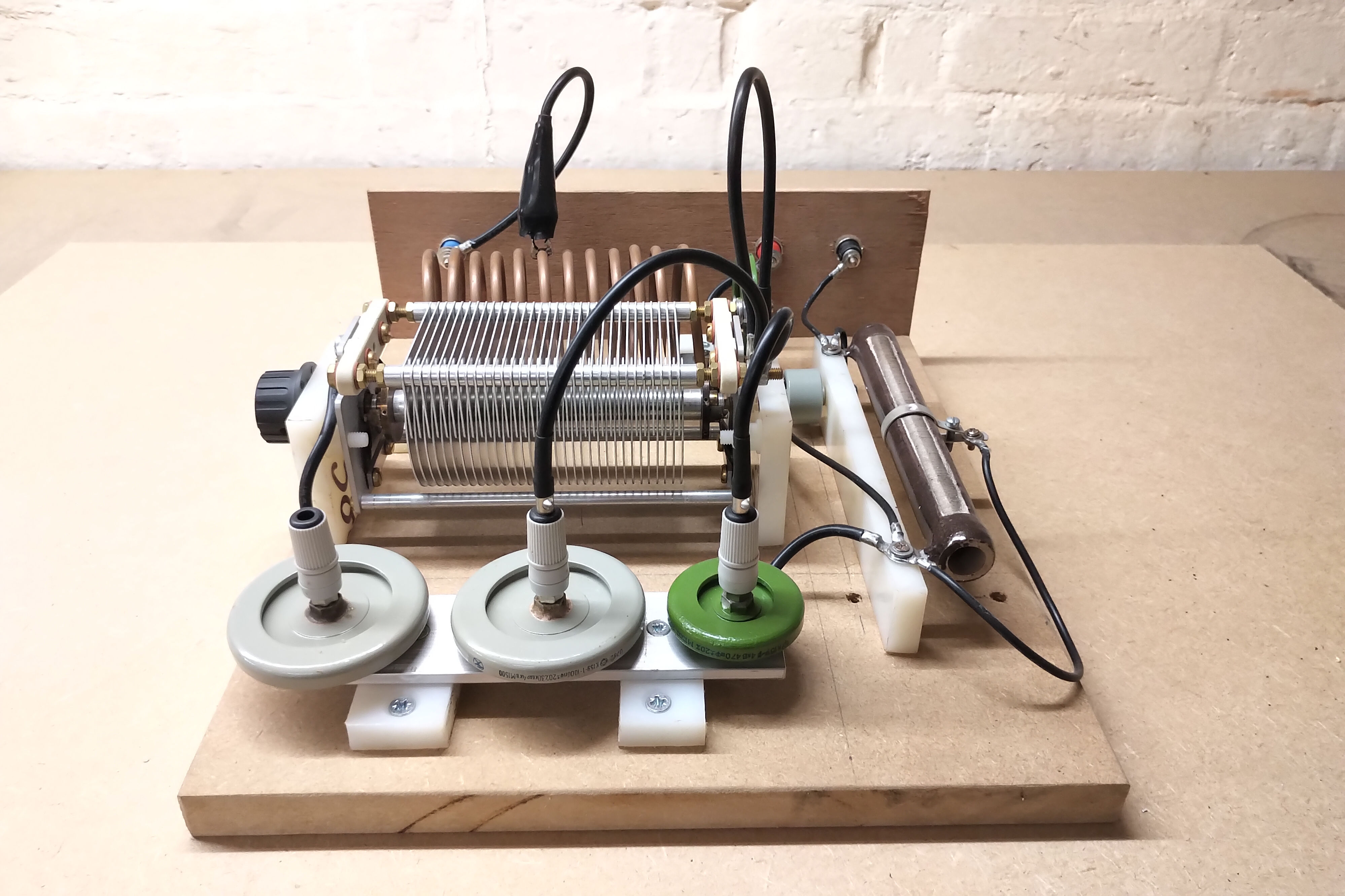
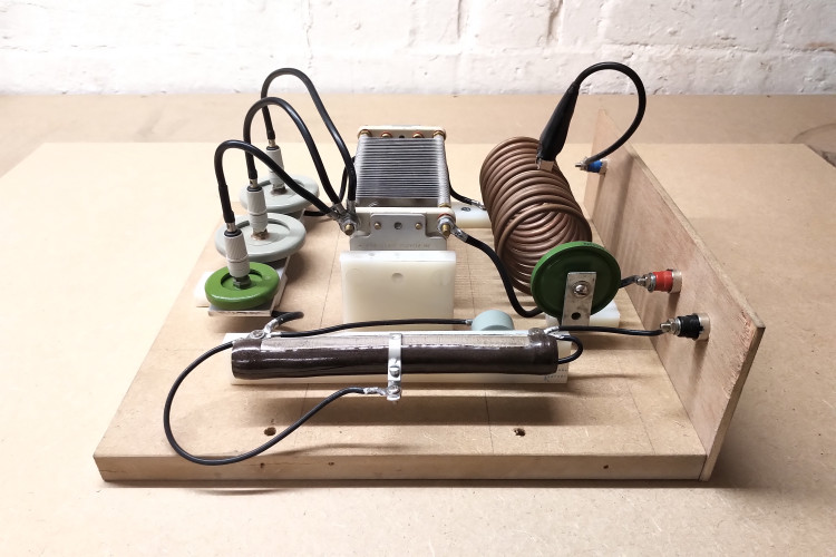
Figures 2 below shows an overview of the VTG apparatus, complete with the high voltage supply, the independent Hartley power oscillator module (HPO), the high voltage bridge rectifier (HVBR), and the supply dc smoothing capacitor.


The circuit diagram for the VTG and peripherals is shown in Figure 2 below, or click here to view the high-resolution version.

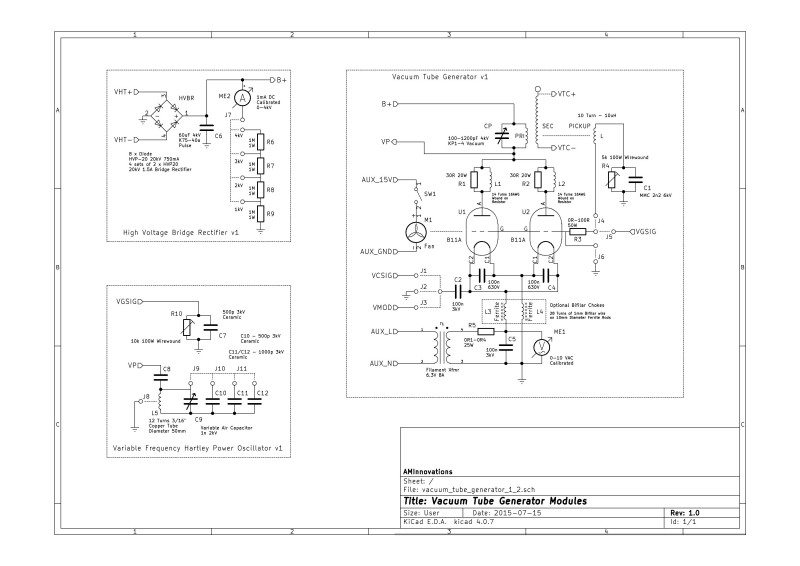
The high voltage supply VHT (described here), is connected to the input of the HVBR. The rectifier consists of 4 sets of 2 x HVP20 20kV 750mA high voltage diodes in parallel and arranged in a bridge configuration. The output terminal of the bridge B is connected to a tank capacitor 60µF 4kV k75-40a Russian pulse capacitor which results in a smoothed dc output suitable for rapid charging and discharging through a primary, or as a stabilised dc supply for the VTG plate circuit.
A dc meter is also so arranged on the output B to read from 0-4kV in configurable steps based on where the base terminal of the meter is connected to a resistor divider. The high voltage dc meter is a simple arrangement using a 1mA fsd (full-scale deflection) ammeter connected to a resistor divider with 4 x 1MΩ resistors. With all four resistors in series 4kV will result in a 1mA passing through the meter moving it to fsd, with one resistor in series 1kV will result in meter fsd, and accordingly for the 2 and 3kV scales. The meter face has been recalibrated to indicate needle reading in kV.
Before considering each of the configurations listed above in detail, it is necessary to cover the basics of the VTG design. The plate supply is provided by the HVBR output B+ and is a variable 0-4kV peak supply either smoothed or unsmoothed based on whether the rectifier tank capacitor is connected or not. The plate supply B+ is connected directly to the driven load LPCP, which in this case is the primary coil in parallel with the primary tuning capacitor. In this arrangement the primary load (parallel resonant circuit) would present the highest impedance to the vacuum tubes when at resonance. When the primary capacitor is so adjusted to set the secondary resonance frequency it is optimal for the impedance of the primary load to be equal to the output impedance of the dual 811A vacuum tubes in parallel. In this way maximum power is developed in the primary load or through the primary of the coil.
It is important to note that when using a VTG the primary circuit, (in this case the load LPCP), is NOT arranged to resonate at the same frequency as the secondary circuit, which avoids large primary currents being developed in the VTG which would lead to excess plate dissipation in the vacuum tubes, and rapid degrading or destruction of the tubes. Rather the impedance of the primary load at the resonant frequency of the secondary coil defines the driving impedance presented to the vacuum tubes, which in turn are adjusted by the grid bias or feedback to match their internal impedance to the driving impedance, leading to maximum power being developed in the primary circuit whilst not overloading the vacuum tubes beyond their maximum ratings.
Hence the VTG drives the coil in a linear sinusoidal CW mode with optimally arranged load impedance matching, as compared with for example, a spark gap generator where the primary and secondary resonance frequencies are arranged to be equal to allow maximum power transfer from the maximised primary currents during the ring-down phase of the primary tank discharge.
The load of the primary is connected to the plates of the vacuum tubes via high frequency chokes L1R1 and L2R2. These chokes quench very high frequency oscillations which can be generated by discharges within the vacuum tubes during overload conditions, and in turn help prevent very high frequency oscillation run-away conditions which can lead to rapid tube destruction.
The cathodes of the vacuum tubes are bridged by RF bypass capacitors to minimise the impedance of the high frequency signal path, and then connected via a sequence of jumpers J1-J3 to allow for different configuration modes. The cathodes are further connected to the heater power supply which provides a constant bias to the cathode combined heater element of the 811A. The heater power supply is a mains step-down transformer so arranged to provide an ac supply of 6.3VRMS @ 8ARMS for two 811A heater circuits in parallel. The heater supply transformer is fine adjusted in this case by R5 which reduces the voltage across the heater elements and has an RF bypass capacitor C5 to again minimise the impedance of the high frequency signal path. The ac voltage across the tube heater elements is monitored using a calibrated 0-10VRMS ac voltmeter, and R5 adjusted, (in this case 4 x 0R1 25W series connected resistors), to provide an optimal 6.3VRMS +- 5%.
When the vacuum tube generator is used as a linear power amplifier in grounded grid (cathode driven) configuration it is necessary to prevent the RF input signal from feeding back into the heater supply and being dissipated in the low impedance power supply stage. To prevent this bifilar high frequency chokes can be used between the tube cathodes and the heater power supply. At low-frequency, (50Hz for the heater supply), current can pass through the choke from the heater supply to the tube cathodes, but the RF signal at the cathode is prevented from feeding back into the heater supply. Modulation and switching via cathode keying can also be arranged via mechanical or semiconductor switches, and allows for a range of “switched” experiments important in the comparisons of electrical phenomena experienced in the exploration of the displacement and transference of electric power.
The grid of the VTG is arranged with jumpers J4-J6 to allow for different configuration modes, and a current limit resistor R3 to restrict the maximum grid current below the nominally rated for the 811A, and according to the configuration it is used in. In addition both 811A’s are forced cooled by the fan driven by the auxiliary 15V supply. Force cooling allows for higher sustained power in CW modes, and affords an additional protection during peak power overloads. It is quite normal for the 811A plate to glow slightly red under higher sustained powers, and in peak power for short periods 0-10s for it to glow intensely red. Sustained high peak powers > ~650W will lead to plate dissipation overload combined with flash-overs between the plate and grid causing rapid grid damage. In most experiments in the displacement and transference of electric power I have found a comfortable sustained power between 400-600W, which leads to long vacuum tube life, and well sustained tube characteristics according to the nominal data.
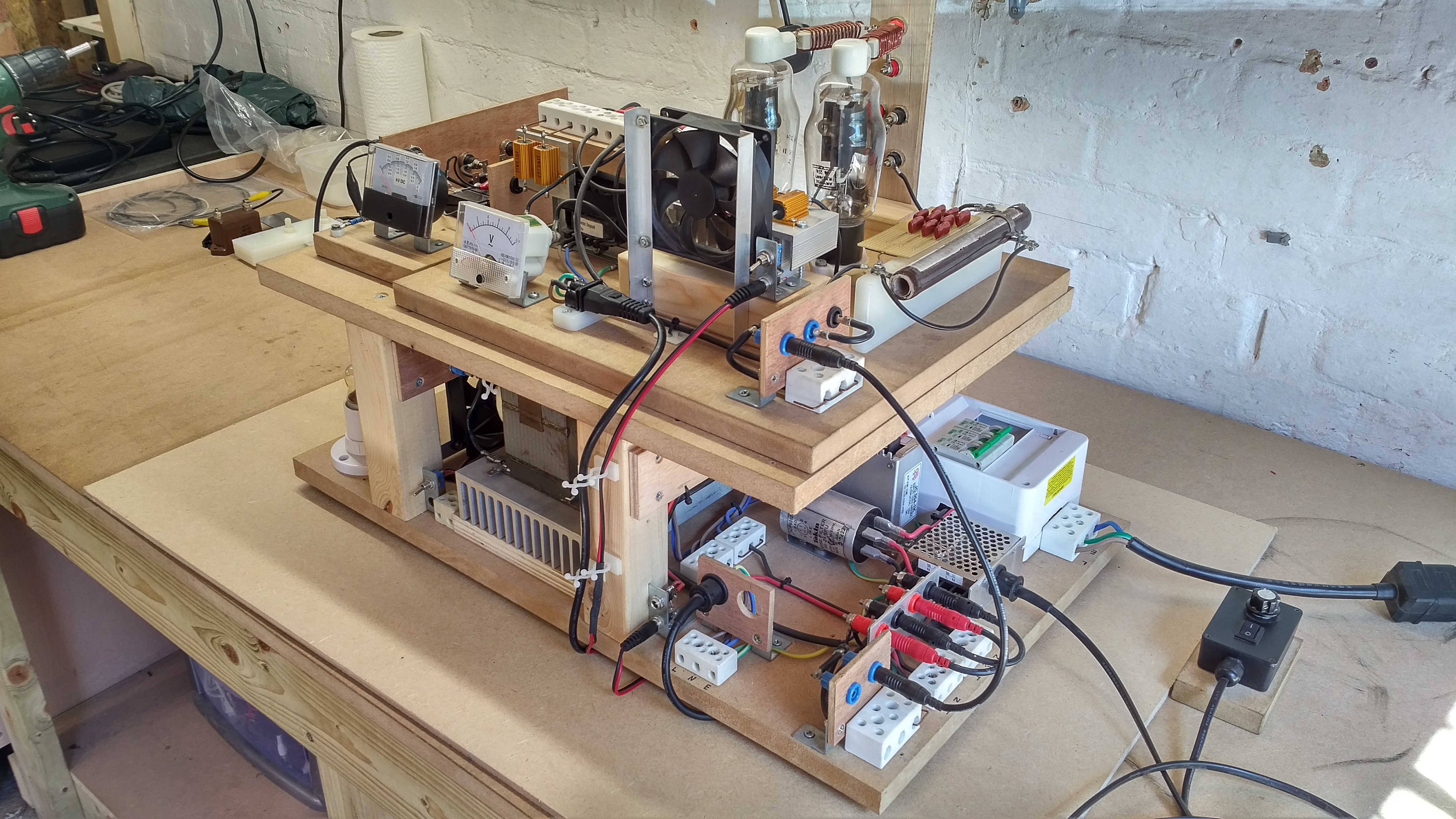
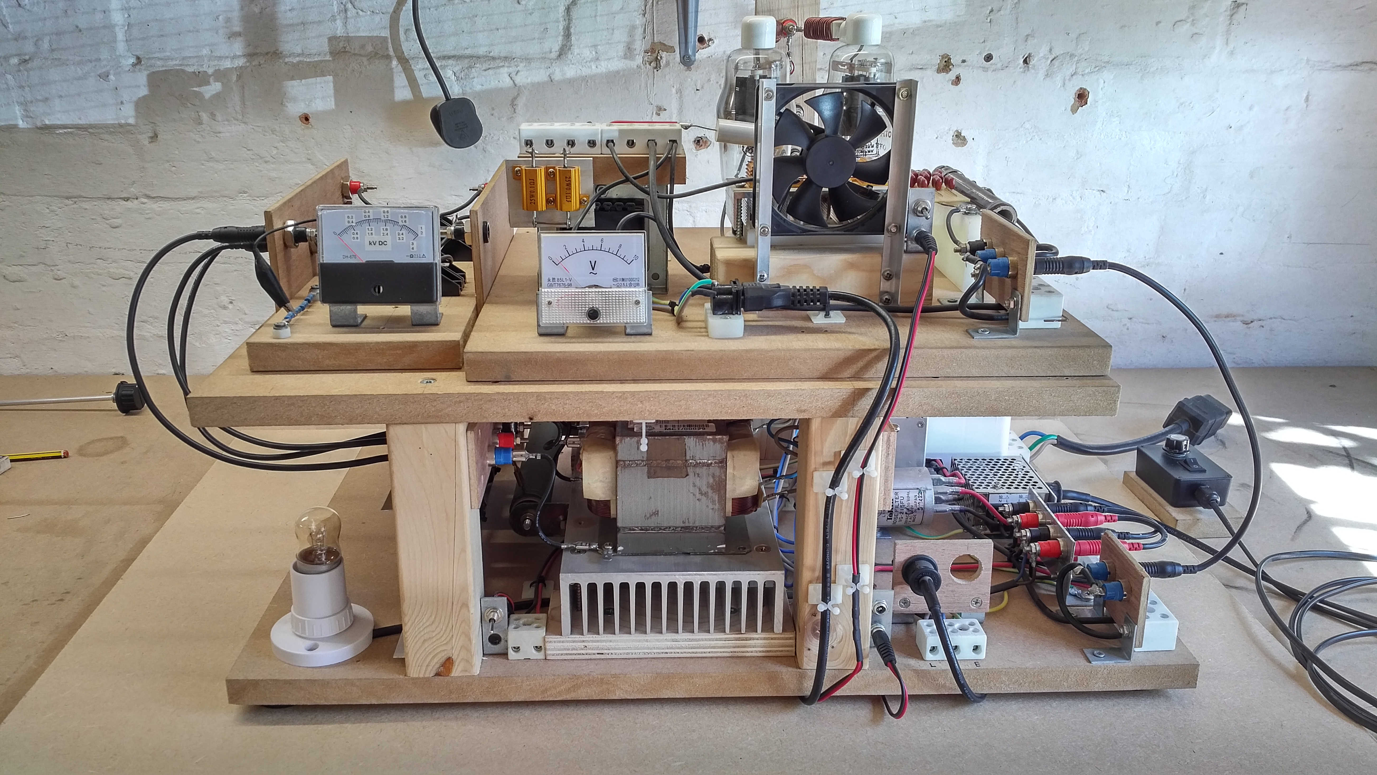
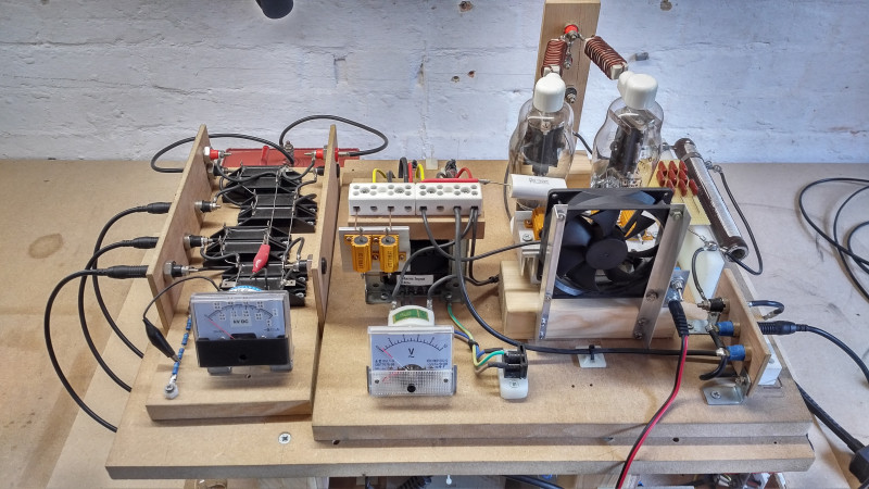
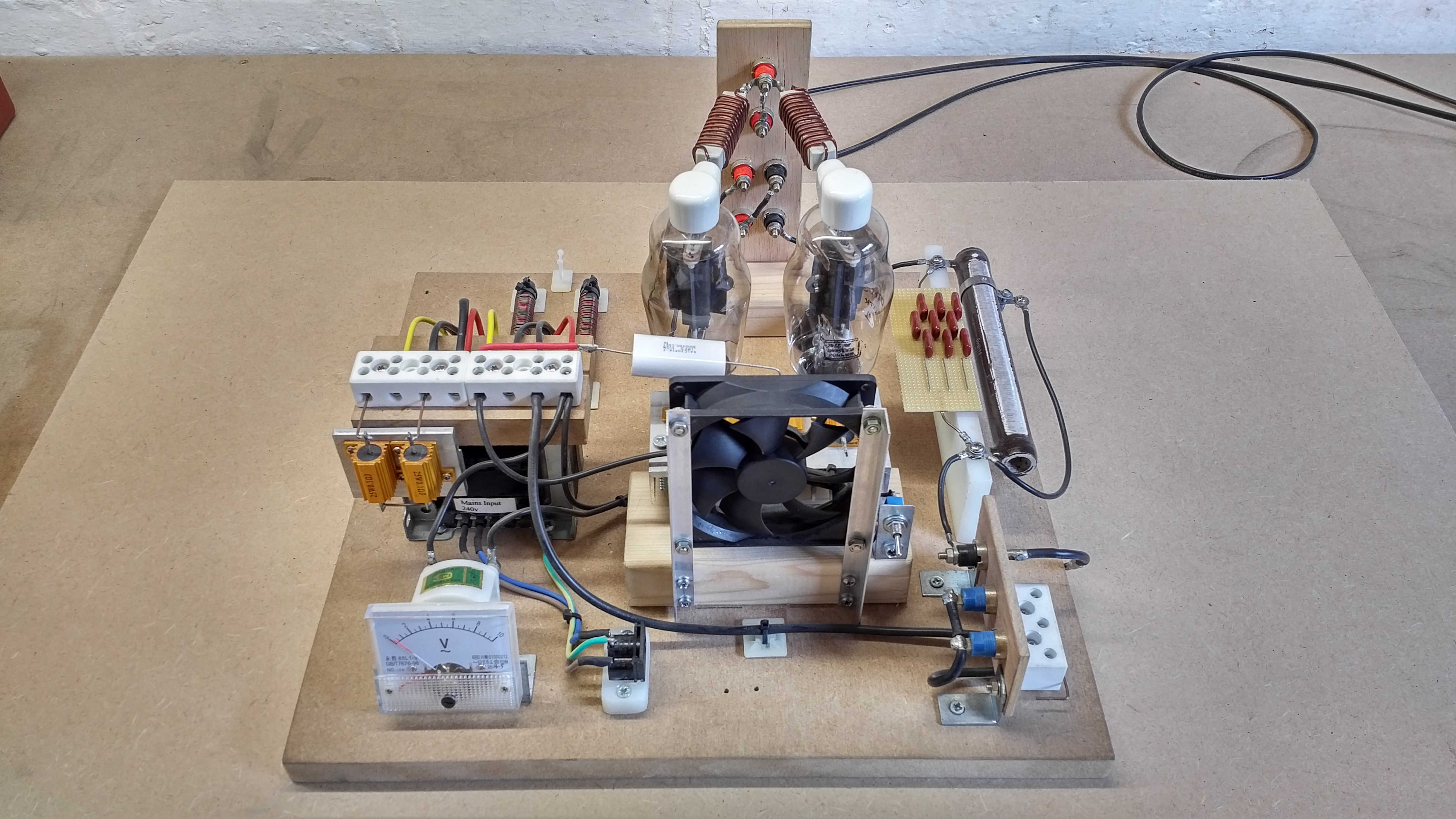
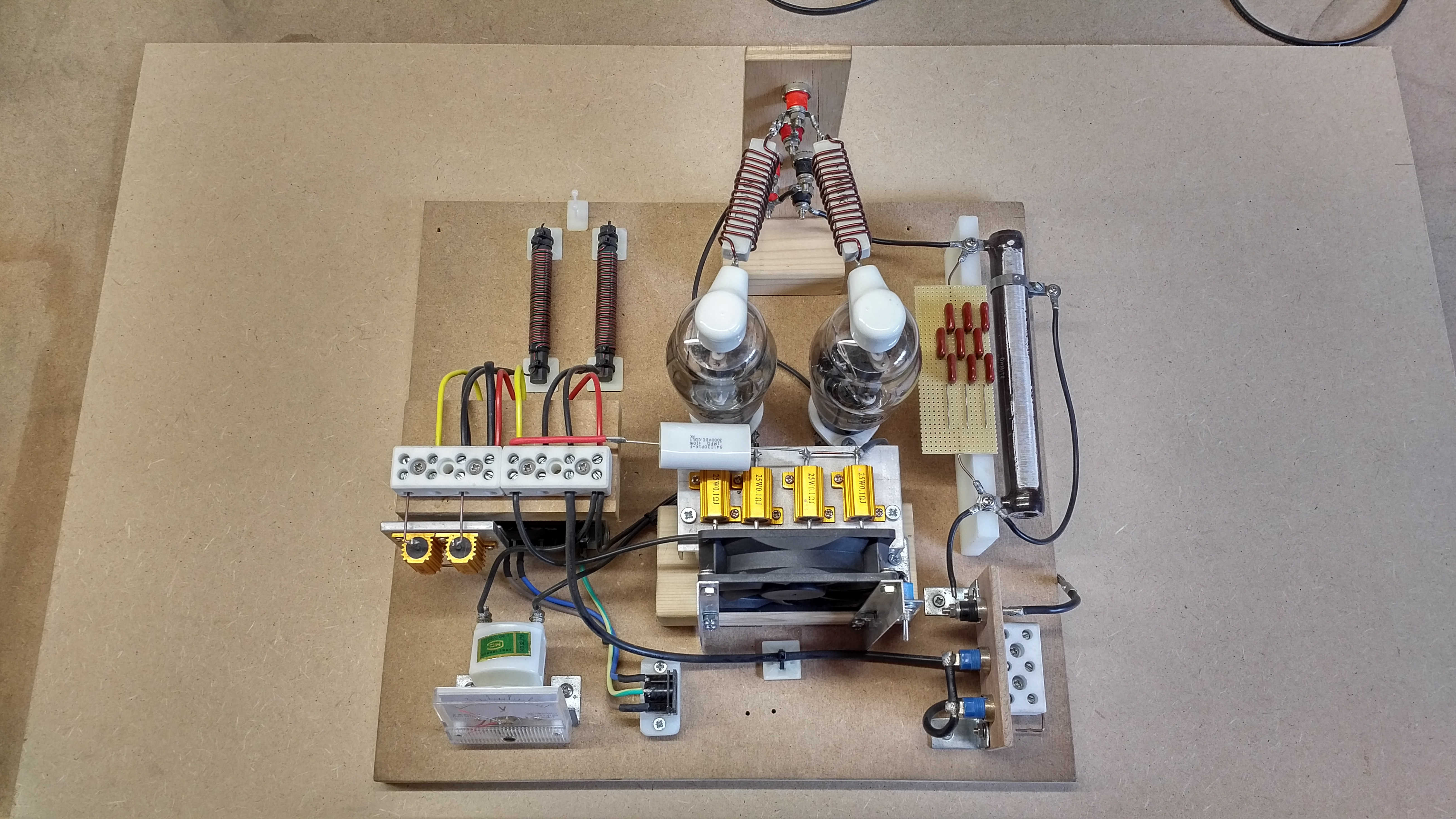
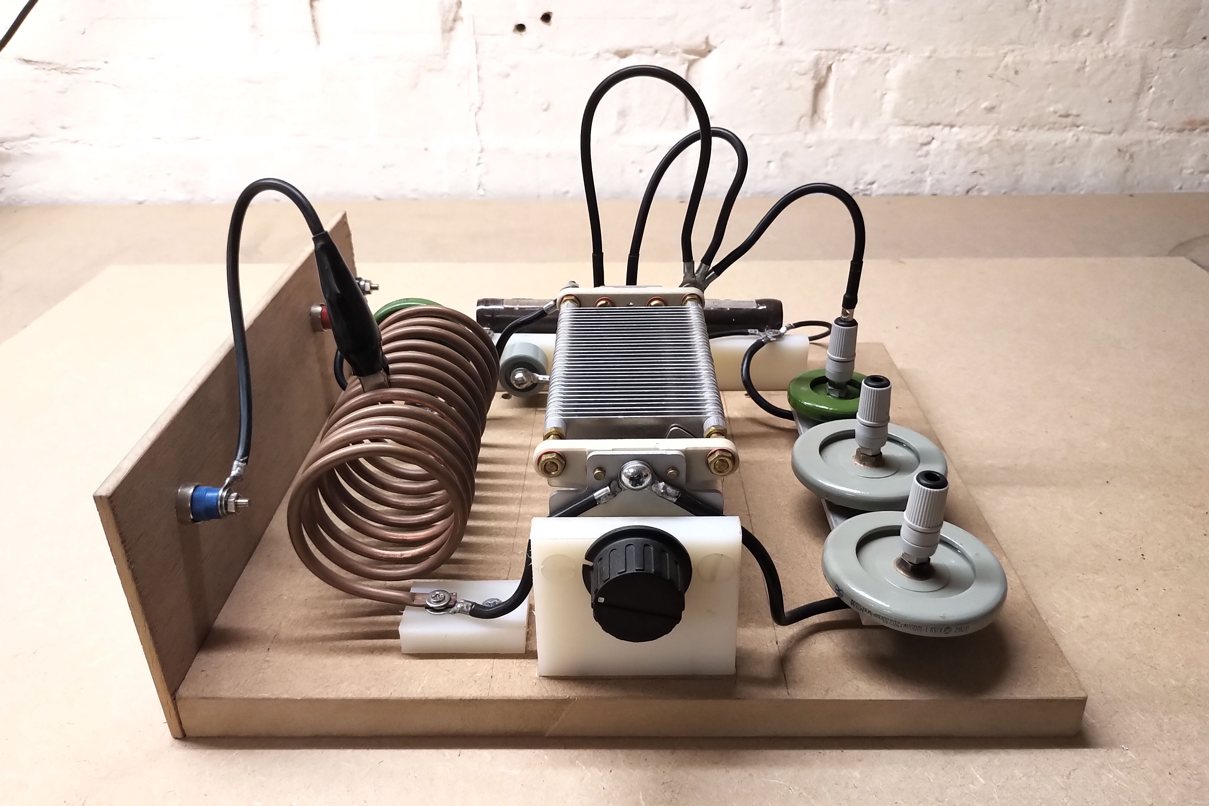
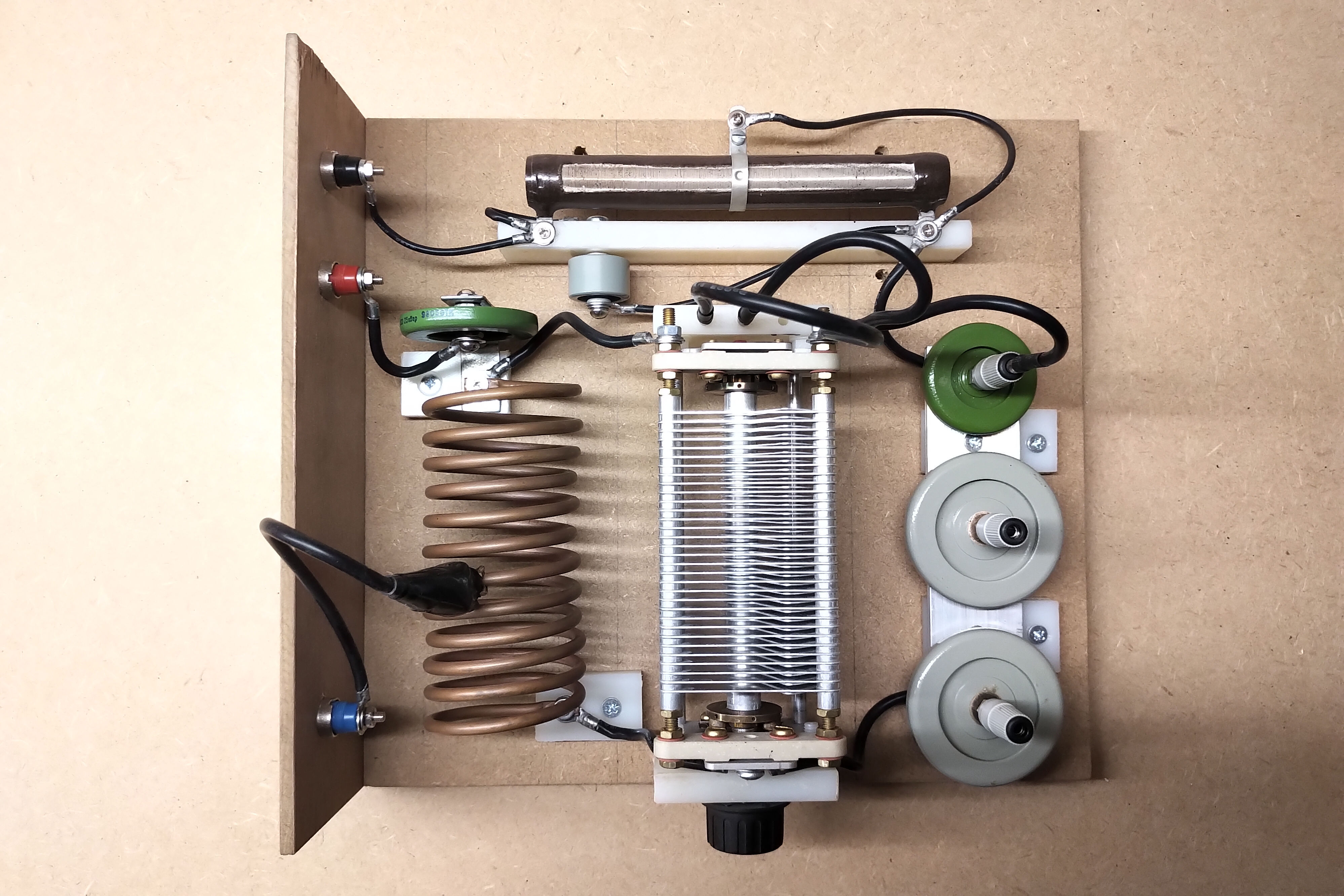
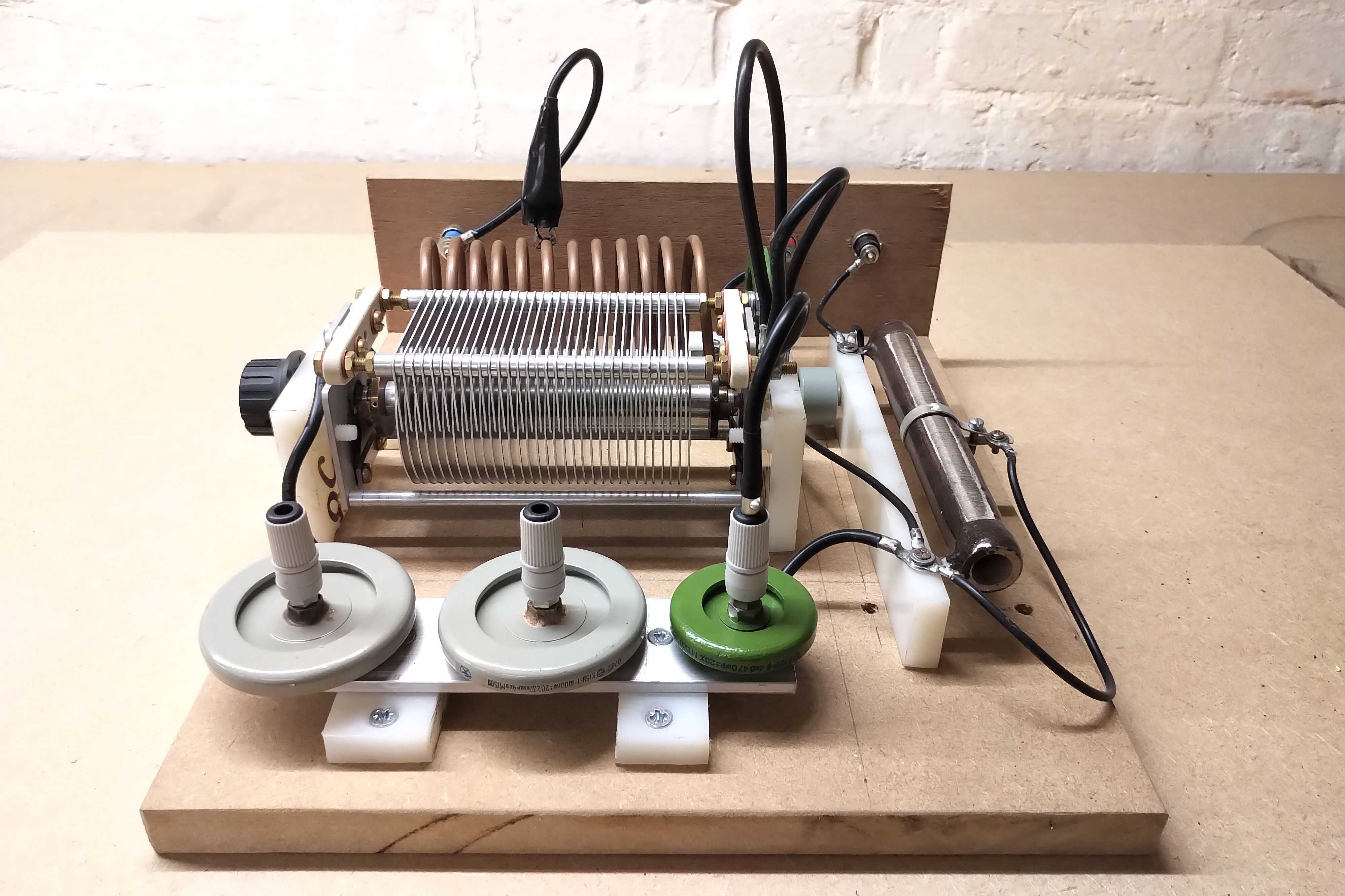
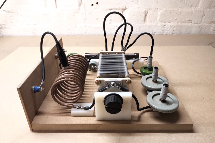
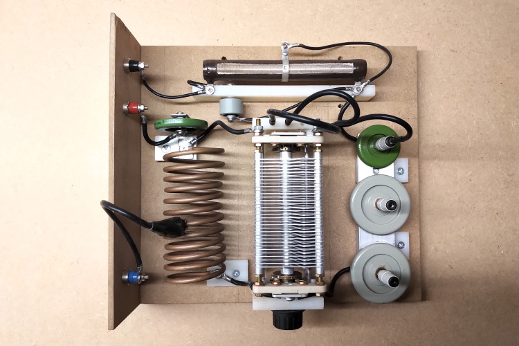
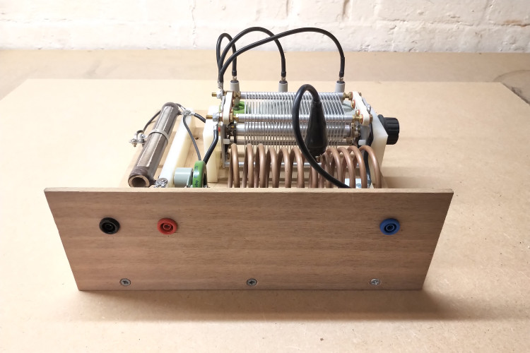
Construction of the VTG and HVBR modules are shown in detail in Figures 3 below. For ease and simplicity of experimentation the VTG is open assembled on a simple board with simple insulated mountings and a combination of metal, plastic, and wooden mounts for the various components. Whilst this does lead to a very quick and flexibly modifiable prototype generator, there are significant EMC, interference, temperature, and stability benefits to housing the entire VTG build within a screened metal case, with directed cooling inlet and outlets, and with careful consideration to connection of high current and tension paths with minimal inductance copper bars etc.


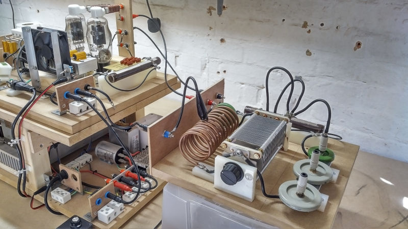
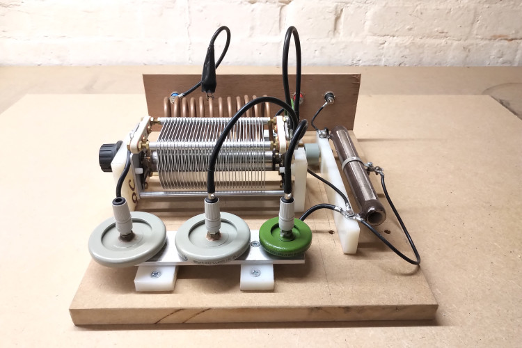
Figures 4 show the construction of the Hartley power oscillator module which is considered further in configuration option 2 below.


The different configurations of the VTG module are now considered in more detail:
1. Tuned plate class-C Armstrong oscillator
This configuration is very well suited to investigations at the upper and lower resonant frequency of the coil being driven (FU and FL). In this case the VTG is a series-fed version of the Armstrong oscillator deriving the grid bias feedback from a pickup coil placed in proximity to the secondary coil. In the case of the flat coil this is a small 10 turn cylindrical coil (diameter 100mm) mounted behind the secondary coil and on axis with the coil centres. Oscillation via the pickup coil feedback automatically keeps the VTG on the resonant frequency being explored and adjusts automatically to maintain the resonant frequency when loading is applied to the secondary coil outputs.
In this configuration J1-J3 are left open and J4 is connected. Circuit operation is as follows. When first turned on the impulse current from the tank circuit B+ conducting through the vacuum tube causes a ringing oscillation (ping) in the primary circuit LpCp. This oscillation couples to the secondary circuit LsCs which is further coupled by the pickup coil to the grid bias leakage circuit. When the phasing of the pickup coil is the correct way round for positive feedback, the grid bias leakage capacitor C1 becomes negatively charged during the positive half cycle in the primary circuit, pushing the grid voltage down and progressively restricting conduction in the vacuum tubes towards the off state with much reduced plate current. The negatively charged grid leakage capacitor C1 then discharges through the grid leakage resistor R4. As this happens the grid voltage on the vacuum tube starts to rise progressively towards 0 volts turning on the vacuum tubes with an increasing plate current. The plate current through the primary circuit LpCp again is coupled to the secondary LsCs and the cycle repeats. With the grid bias leakage circuit correctly adjusted the VTG will oscillate with a linear sinusoidal output optimised for maximum plate voltage and current swing, (maximum power transfer at the resonant frequency of the secondary), whilst keeping the grid bias currents within the maximum ratings for the vacuum tubes used.
When setting up this mode of operation it is most important to ensure correct phasing of the pickup coil in connection to the grid bias leakage circuit, and that the values of C1 and R4 are suitably adjusted to allow maximum swing of the plate circuit whilst keeping the grid bias within the maximum ratings. For this VTG with 2 x 811A vacuum tubes R4 is optimally between 1-1.5kΩ and C1 between 1.5-3nF. Considerable power dissipation occurs in R4 when running the VTG at higher powers > 400W, hence the need for a wire-wound power resistor (100W), and preferably as part of the forced cooled air circulation. Excessive or too little grid bias current will lead to a distorted and clipped oscillation, or in extreme cases, no oscillation at all and rapid vacuum tube degradation or destruction. Initial setting up is best done with low plate voltage ~ 500V and higher values of R4. R4 can then be progressively reduced to increase grid bias whilst ensuring a clean and stable output oscillation.
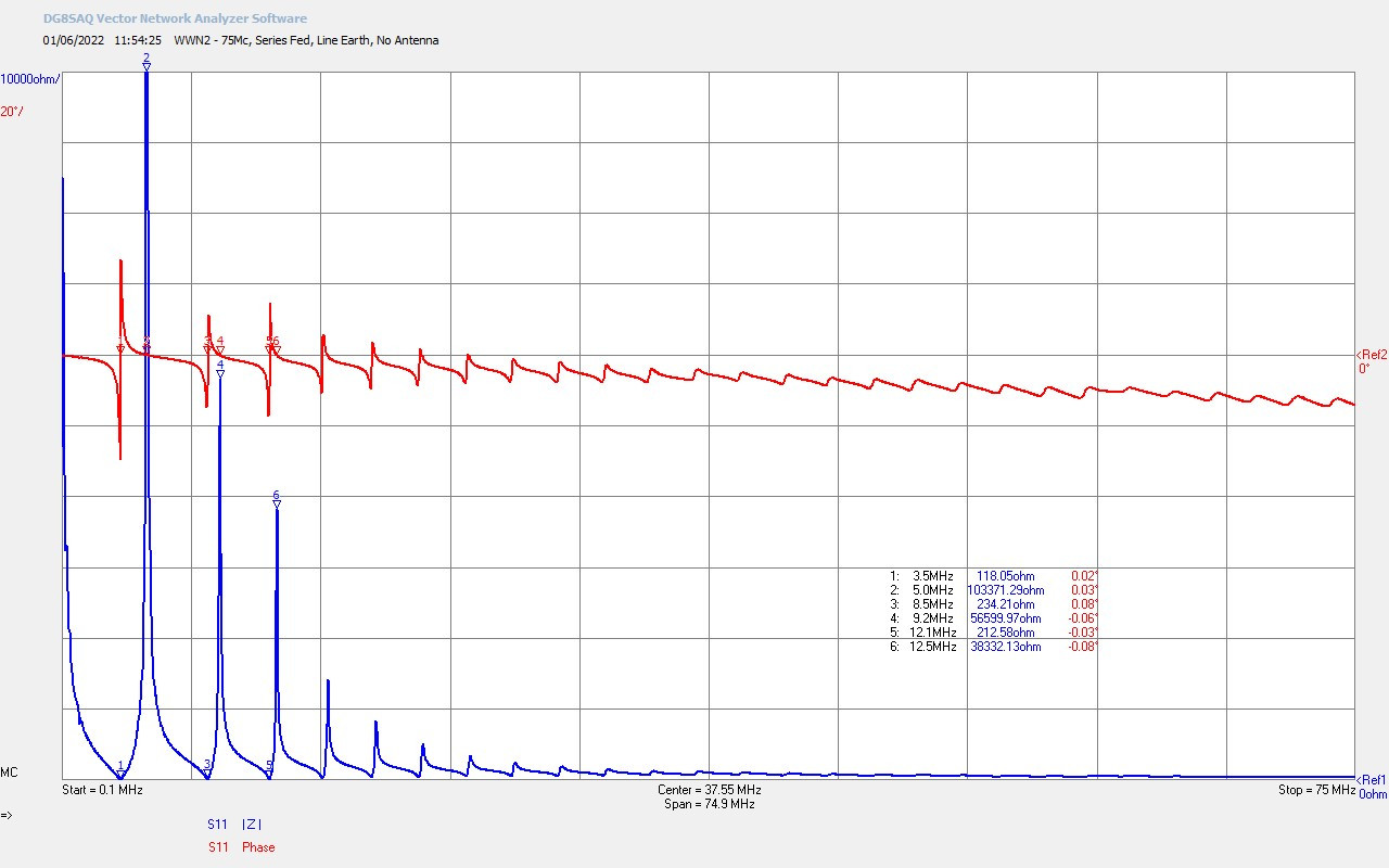
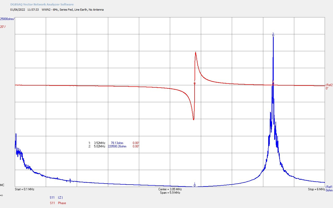
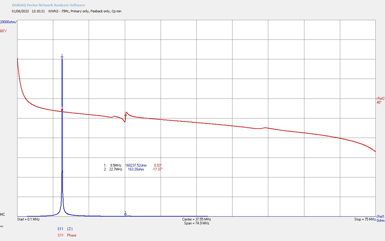
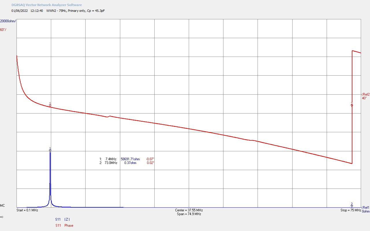
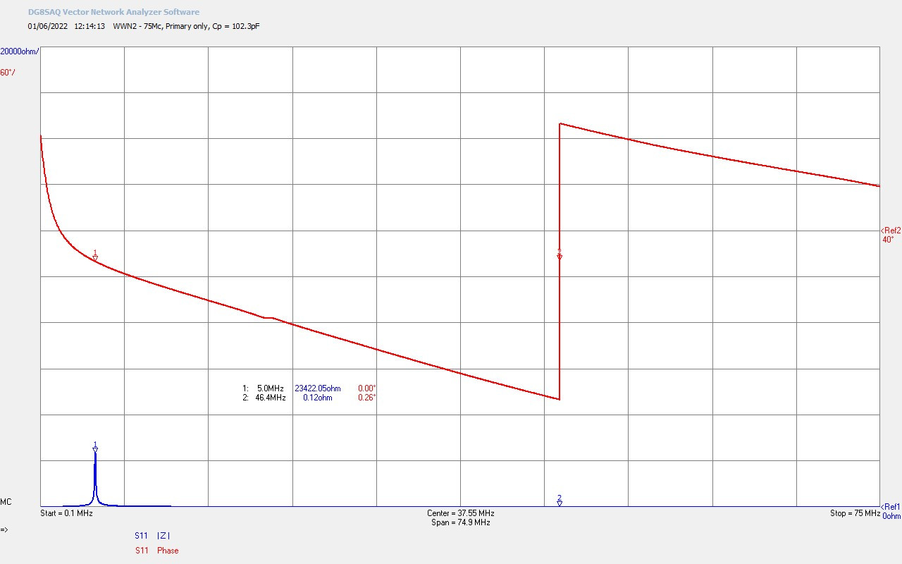
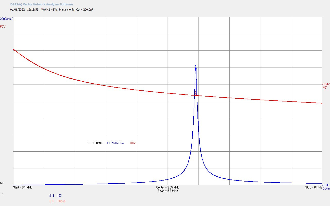
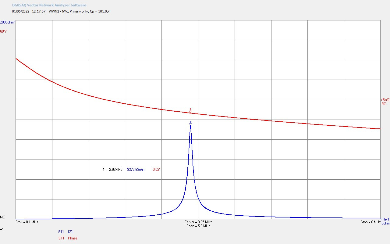
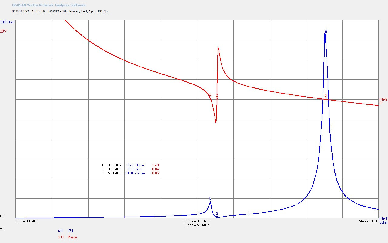
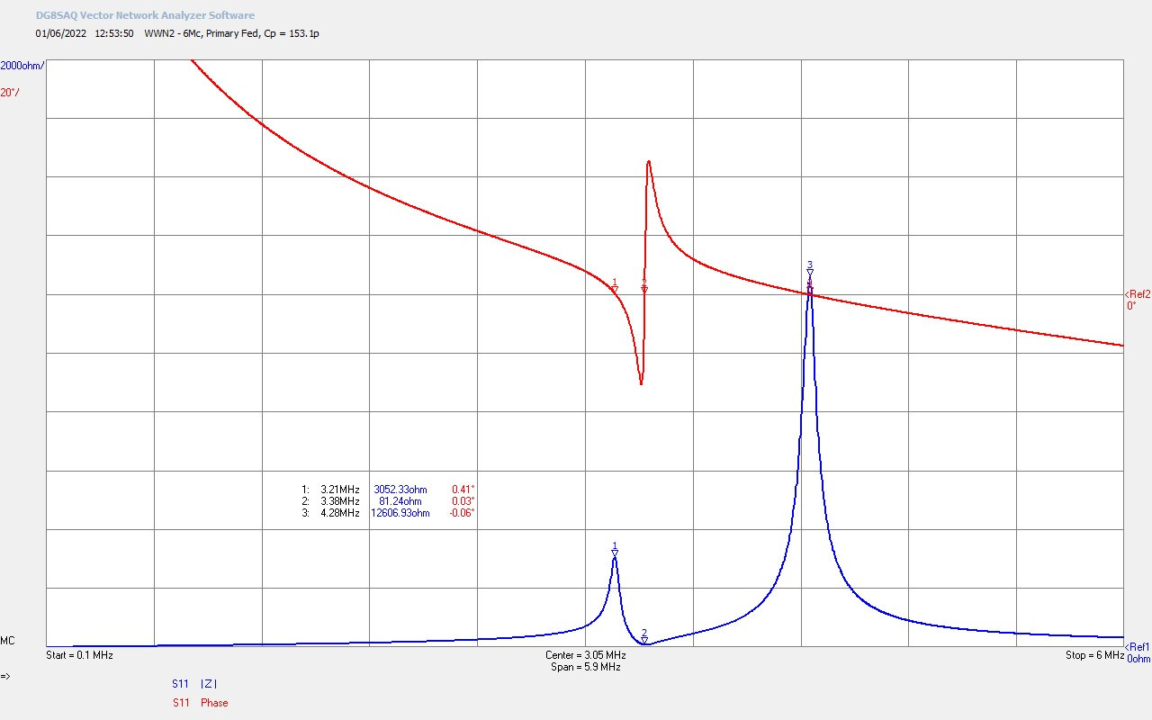
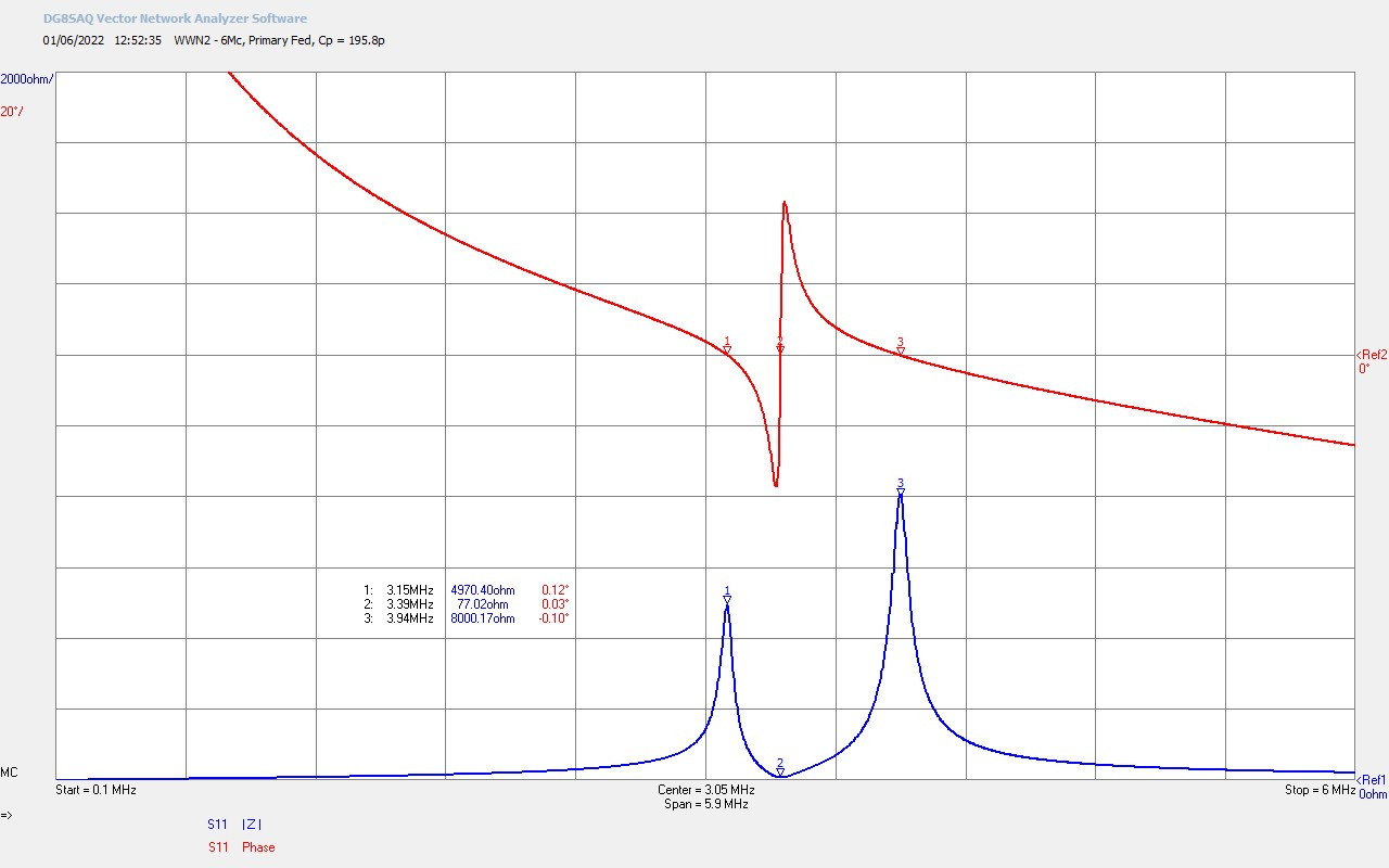
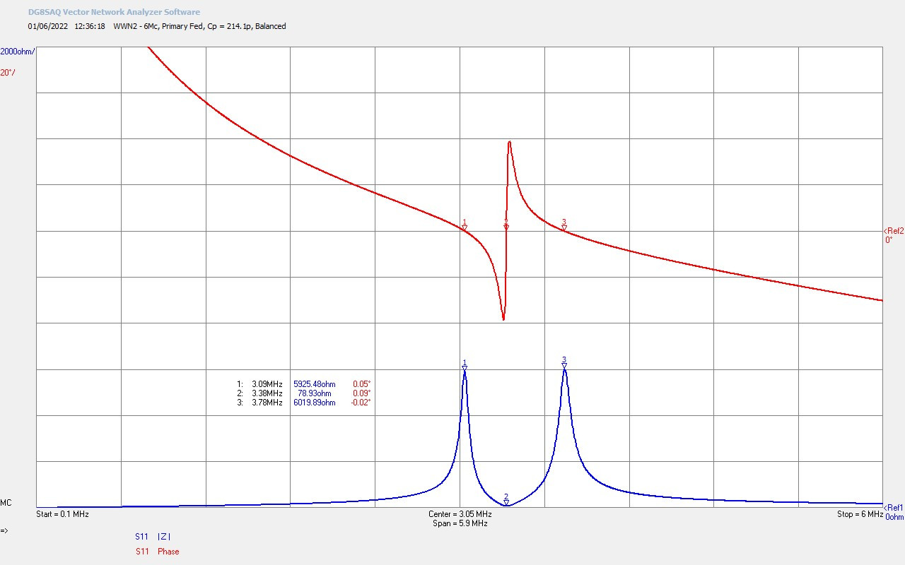
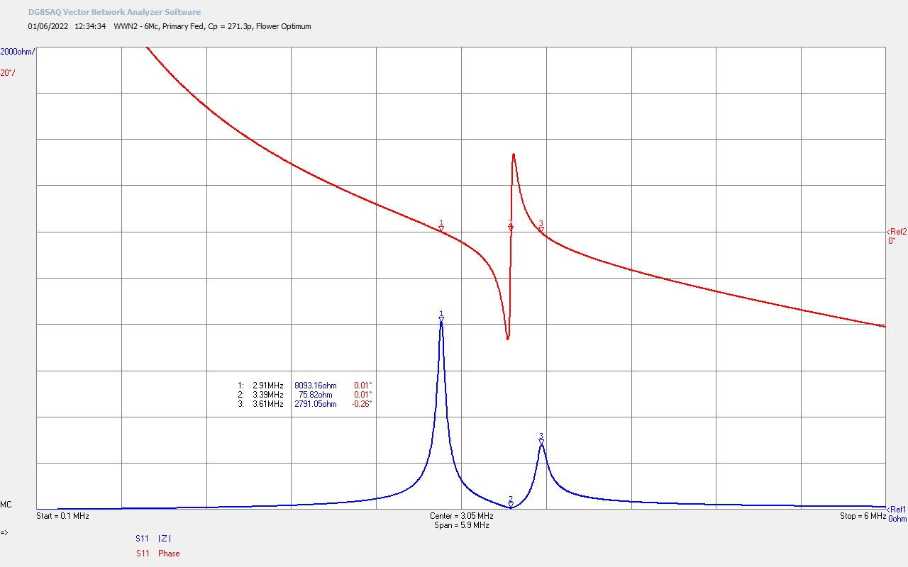
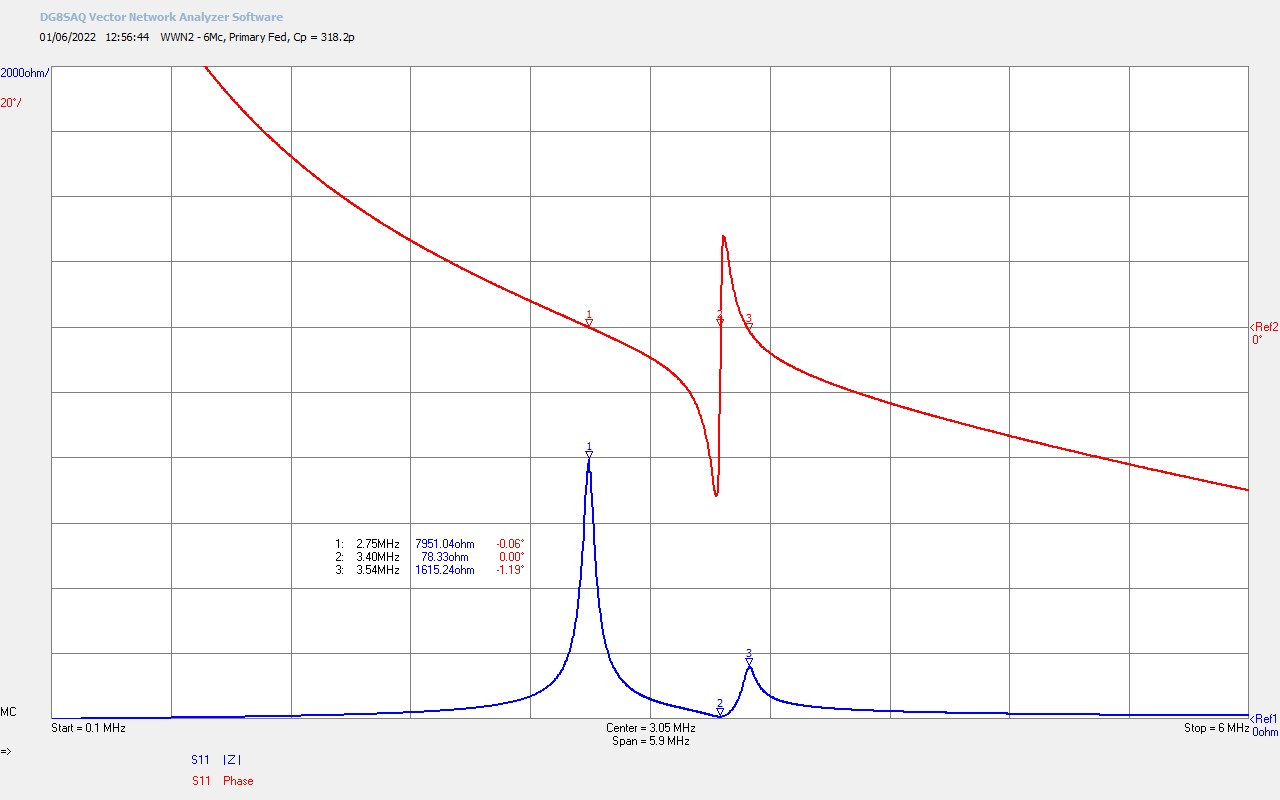
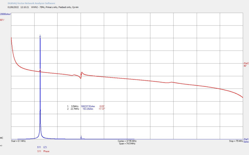
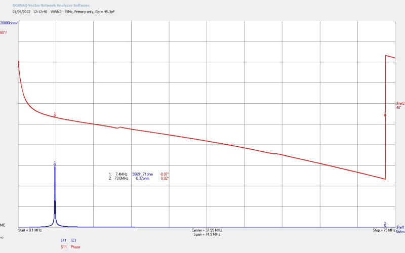
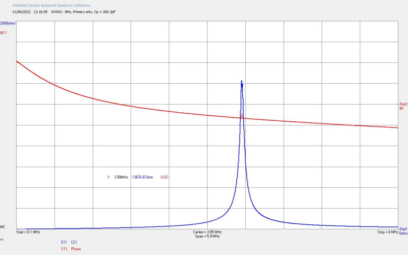
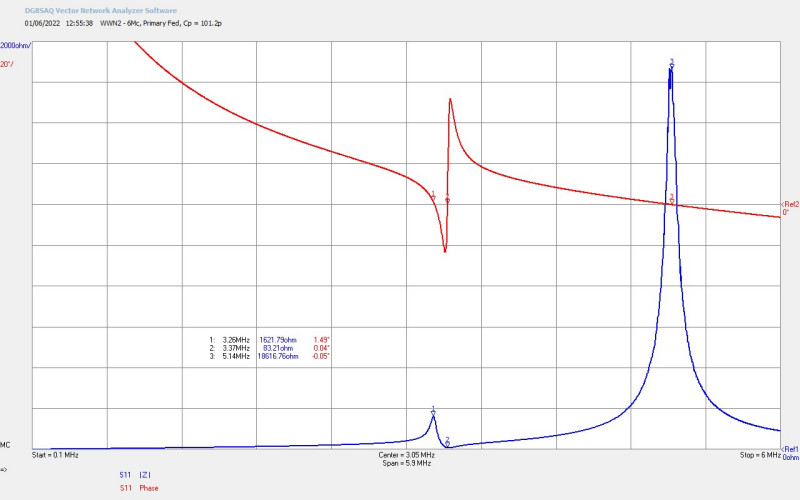
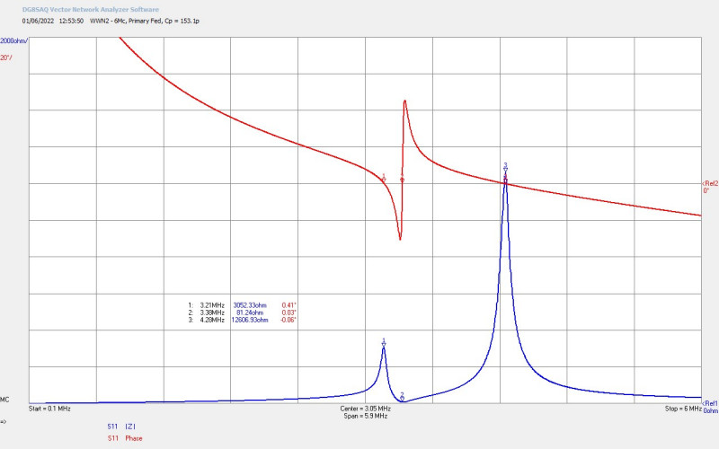
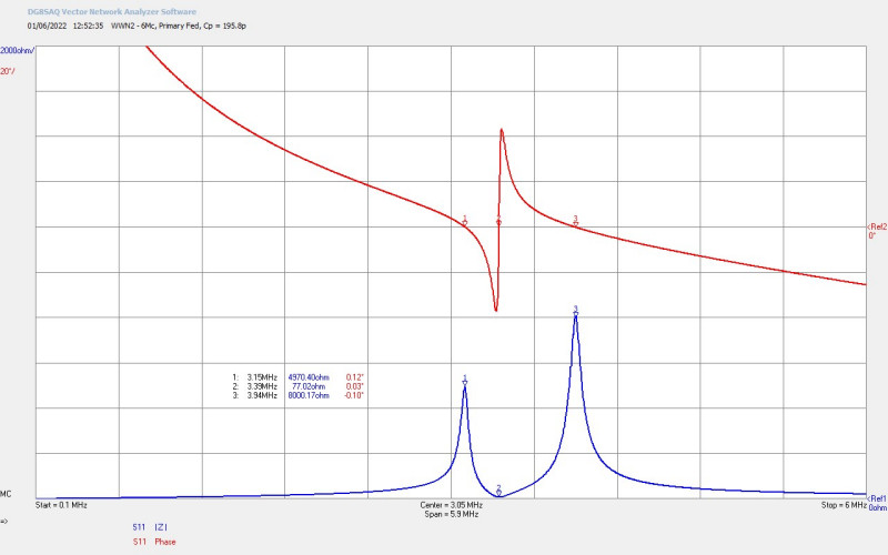
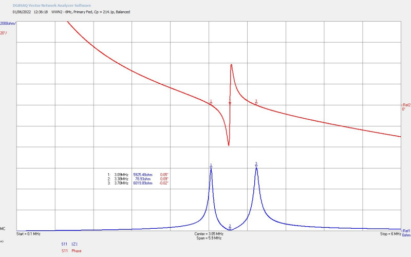
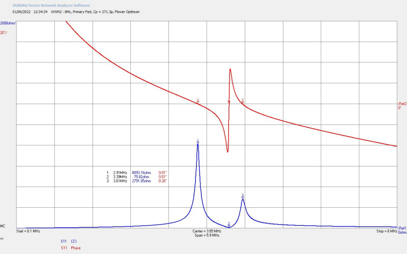
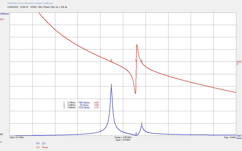
As seen in previous impedance measurement posts for the flat coil (1S-3P) the resonant frequency of the secondary can be adjusted by changing the capacitance of the variable vacuum capacitor in the primary Cp. When adjusted the oscillating frequency of the VTG automatically changes to track the changes in the secondary resonant frequency. At high values of Cp > ~650pF the impedance of the lower resonant frequency FL is dominant and the final oscillating frequency can be adjusted around this frequency FL in the range 1.5-2.2Mc/s. At low values of Cp < ~650pF the impedance of the upper resonant frequency FU dominates and the final oscillating frequency is in the range 2.7-3.8Mc/s.
Adjusted in this fashion this configuration of the VTG is very well suited to continuous linear measurements for single wire currents, displacement and transference of electric power, and telluric transmission experiments. This configuration is best suited to exploring frequency regions centered around FU and FL, where oscillation is stable and conduction currents in the secondary of the experimental coil are > 10mARMS. This configuration is not suitable for exploring frequency regions far from resonance, at very low bias currents, or between the transition between FU and FL. In these cases it is necessary to use the VTG in modes 2 or 3 where accurate progressive frequency control is provided by an external source and the VTG acts as a power stage, whether that be as a tuned power oscillator, or as a linear power amplifier.
2. Variable frequency Hartley power oscillator
The Hartley power oscillator converts the VTG to a linear oscillator which can be adjusted for variable frequency in bands defined by the combination of band capacitors connected on the HPO module. The frequency of oscillation of the VTG is now determined by the resonant circuit formed on the HPO board, the pickup coil of configuration 1 is not connected in this arrangement. This configuration is suitable for measurements across the entire frequency band of interest, in the case of the flat coil 1S-3P between 1.5-3.5Mc/s.
The HPO must be manually tuned or retuned to a specific frequency of interest and particularly when changing the loading of the secondary coil circuit. The resonant frequency of the secondary coil is very sensitive to electrical loading, temperature, material losses, changing boundary conditions and proximity, which all cause deviations of the configured frequency. Any change in this tuned frequency requires re-adjustment making the HPO configuration not well suited to experiments designed to explore different loads and operating conditions. It is however very suited to exploring circuit operation where the loading conditions are relatively fixed, and particularly in off-resonance, low current, and frequency transition regions.
In this configuration J1-J3 are left open and J5 is connected to the Hartley oscillator module along with the plate voltage and RF ground as shown on the circuit schematic of Fig 2. The bands of frequency can be adjusted by hardwired jumpers on the HPO module, where the static band capacitors are combined with the 1000pF variable capacitor, and form a parallel resonant circuit with L5 the HPO coil with an inductance of 3.0uH. The available bands are broadly as follows (static combinations of capacitors shown only):
a. 1 x 500pF = 2.4 – 4.1Mc/s
b. 1 x 1000pF = 2.1 – 2.9Mc/s
c. 1 x 500pF + 1 x 1000pF = 1.8 – 2.4Mc/s
d. 2 x 1000pF = 1.7 – 2.1Mc/s
e. 1 x 500pF + 2 x 1000pF = 1.5 – 1.8Mc/s
The setup of the HPO again requires a balance between largest plate swing (output power) without distorting the output wave, whilst restricting the grid bias within maximum parameters. The required frequency band is first configured using the hardwired jumpers, and the HPO grid bias variable resistor is set in the higher halve of its resistance range . The VTG plate supply is first set low at 500V and the HPO coil tapping point starts close to the RF ground end. The tapping point can be progressively moved upwards towards the plate voltage end of the coil until a point is reached where the output of the VTG is stable, clean, and with good power output as the plate supply is progressively increased up to the maximum ratings for the vacuum tubes. The HPO grid bias resistor can then be progressively reduced keeping the grid bias current within the maximum recommended. If no oscillation can be obtained the grid bias resistor can be progressively reduced until oscillation starts, whereupon the other adjustments discussed can be continued with.
The HPO can then be varied across its band frequency range according to the experimental requirements of the circuit, and the output power adjusted using the plate supply voltage. If the loading on the secondary coil changes significantly the HPO will need to be re-tuned and/or re-adjusted to provide stable power oscillation. Off resonance of the secondary coil in the experiment may require the HPO tapping point to be re-adjusted towards the RF ground to prevent excessive power dissipation in the coil. During continuous operation the temperature of the HPO inductor coil should be monitored in order to prevent over-heating. Re-adjustment will be required when moving often and rapidly between on-resonance and off-resonance operating points. As previously stated this configuration mode is best suited to exploration of operating points not accessible with configuration 1, and where the operating conditions do not change rapidly during the measurement cycle.
3. Linear amplifier output stage
The VTG can be operated as the power stage of a linear amplifier when correctly configured and connected to a suitable frequency generator with power amplifier output stage. No pre-amplifier stage is currently provided in the VTG so the driving signal source will need to generate an output between ~ 1-10W in order to the drive the VTG output to a usable output power. In this configuration the VTG can be driven in grounded grid, grid biased, or even as a cathode follower with some change of circuit connection and setup.
For grounded grid operation J1 is connected to the external signal source, and J6 is connected directly to RF ground. For grid driven mode J1-J3 are open and J5 is connected to the external signal source which in this case also needs to arrange for the driving signal to provide suitable dc grid biasing for the vacuum tubes used. For this reason grounded grid operation is preferred for simple linear amplifier operation.
When correctly setup and driven the VTG in this configuration can provide a very stable oscillation output which can be easily and finely adjusted by the external signal source, overcoming some of the adjustment problems of the HPO, but not exceeding the very good power output levels of the HPO. It has been found that the HPO is better when higher power experimentation is required, but the linear amplifier is better for overall signal stability and accurate adjustment. This configuration also allows for non-sinusoidal waveforms to be applied to the experimental system.
4. Modulator stage
Modulation of the VTG is currently by cathode keying, allowing conduction through the vacuum tubes to be switched at low frequencies via mechanical switches and relays, or at higher frequencies < 100kc/s by semiconductor MOSFET switches. Modulation of this kind was originally considered to be important in the exploration of the displacement of electric power where non-linear events play a very significant part in the unusual electrical phenomena observed within an electrical system. It has since been found through experimentation that the non-linear impulses generated by this modulation method are not of sufficiently low transition time and low pulse width to be particularly useful in the generation, observation, and measurement of displacement phenomena.
5. CW and burst oscillation modes
The VTG can be arranged in any of the configuration modes 1-4 and then operated in CW or burst modes simply by removing the plate supply tank capacitor at B+. When the tank capacitor is connected at the output of the HVBR a constant plate supply voltage B+ is applied to the primary load. In this case the output of the VTG in oscillation will be in CW mode providing a constant and continuous oscillation wave to the primary circuit LpCp.
When the tank capacitor is removed from the HVBR the output is an unsmoothed full wave rectified supply at 100c/s (based on UK line frequency). Applied to the VTG this produces bursts of oscillation inside the supply envelope, and has proven to be useful in establishing certain operating conditions in experiments orientated to displacement of electric power. These operating conditions and experiments are currently work in progress and will be reported in subsequent posts.
Overall the VTG has proven itself to be a versatile and reliable linear power source suitable to drive a wide range of experiments to explore the displacement and transference of electric power, and also some preliminary lower power telluric transmission experiments. Over several years of operation only 1 x 811A has been replaced after grid flash over destroyed one of the tubes when being used in configuration 2 with the HPO at an off-resonance operating point, with large output mis-match and high reflected power. The VTG has also sustained reliably through high power experiments where both plates of the tubes are glowing bright red for short periods of time. The 811A in RCA and Russian forms have proven themselves to be robust and reliable provided the heater element (spring tensioned) has not broken during extended storage. VTGs with other vacuum tube types and configurations will be presented in subsequent posts.
Click here to continue to the next part, looking at Tube Power Supply – Heater, Grid & Screen.