Tesla’s Radiant Energy and Matter

Some of the most fascinating areas of research into the inner workings of electricity, are those that display unusual and interesting phenomena, and especially those not easily understood and explained by mainstream science and electromagnetism. The field surrounding Tesla’s radiant energy and matter, the apparatus, experiments, and wealth of unusual electrical, and even non-electrical related phenomena, is a particular case to note. This first post in a sequence serves as a practical and experimental introduction to this area, along with consideration and discussion of the observed phenomena, and possible interpretations as to their origin and cause. It is through working to understand these types of phenomena, often generated in high tension, unipolar, and non-linear electrical systems such as the Tesla coil and TMT transmission system, that the inner workings of electricity can be revealed little by little. That is to say, the outer workings of electromagnetism that account for almost all of those measurable electrical properties that constitute the transference of energy, and hence electric power, between source, load, and the intervening transmission medium, can be peeled back to show a more fundamental, coherent, and guiding mechanism.

This second inner level of electricity’s mechanism and working I consider to be based on the principle of displacement, a coherent and dynamic state extending throughout the common medium, and where the electric and magnetic fields of induction are defined but as yet undifferentiated in their nature. These two undifferentiated facets we can only suppose originate from a yet deeper and hitherto unexplored level of inner workings, where the pressure applied by the one and only force of intent leads to the manifested universe, and all that is both known and unknown.

The differentiation of the electric and magnetic fields of induction lead to the outer manifestation of electricity as we commonly know it, transference, and all the electromagnetic properties and scientific measurements that accompany it, including, for example, the speed of light c in the vacuum, which only currently has a fixed and defined value based on the level it is measured and perceived at. At this outer level of transference, c is measured as a specific value based directly on the inter-action (propagation) of the differentiated electric and magnetic fields of induction. I conjecture that at the next inner level where these fields of induction are defined but not differentiated, that c has not only different measurable quantities, but also comes with qualities and properties that make it a multi-faceted vibration, rather than the simple linear measure of a fixed value.

It should be clear to the reader that in my interpretation of this field of research I see it as not enough to construct experiments, observe phenomena, measure quantities, and then try to fit this to a linear and physical way of thinking about the world, as is the case in mainstream science, and often even in the alternative approaches. I consider progress in this field of research to be a co-operation or union between high-quality science, and a more philosophical or esoteric understanding of the principles and processes of life. Only through new practical knowledge gained through this inclusive approach to life will it be possible to fully reveal, perceive, and utilise the inner workings of progressively deeper levels of electricity.

Such are my conjectures about the inner workings of electricity even at only the next inner level, that as of yet is an unknown mystery to both mainstream science, and the alternative electricity researcher alike. It is for this reason that I find experiments surrounding Tesla’s radiant energy and matter, and associated phenomena, so fascinating, exciting, and awe-inspiring, as they provide an opportunity to progressively take a look “under the hood” at the world of displacement, a hidden world yet to be discovered. A world much more vast in its import and effect than that which we currently observe, understand, and utilise.

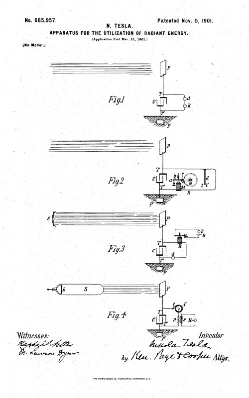
In Tesla’s[1] original patent of 1901, No. 685957, he describes his understanding of radiant energy gained from experimentation and observation, and suitable apparatus for utilising this radiant energy:

“My own experiments and observations, however, lead me to conclusions more in accord with the theory heretofore advanced by me that sources of such radiant energy throw off with great velocity minute particles of matter which are strongly electrified, and therefore capable of charging an electrical conductor, or, even if not so, may at any rate discharge an electrified conductor either by carrying off bodily its charge or otherwise.”

“When rays or radiations of the above kind are permitted to fall upon an insulated conducting body connected to one of the terminals of a condenser, while the other terminal of the same is made by independent means to receive or to carry away electricity, a current flows into the condenser so long as the insulated body is exposed to the rays, and under the conditions hereinafter specified an indefinite accumulation of electrical energy in the condenser takes place. This energy after a suitable time interval, during which the rays are allowed to act, may manifest itself in a powerful discharge, which may be utilized for the operation or control of mechanical or electrical devices or rendered useful in many other ways.”

It is clear from Tesla’s own description that he saw radiant energy as a ray or beam-like emanation, that is capable of transferring energy between the emanating source, and a suitably arranged receiver. Under these conditions an electric current could be established when the radiant energy is accumulated in a capacitor and connected to an electric load.

Tesla also states that a suitable time interval is required to allow the rays to generate an action upon the receiver. Tesla conjectures that radiant energy causes minute particle to be thrown of at great velocity, both making a link between radiant energy and matter, and implying that a force can be exerted not only electrically but also physically on a distant body.

In my own experiments into radiant energy I have observed similar phenomena to those described by Tesla including, charging of capacitors from longitudinal wavefronts generated in the single wire cavity of a TMT system, electrical and physical forces exerted on conductors, insulators, and biological specimens placed in proximity to a source of radiant energy emanations, and electric currents and discharges when load circuits are connected to a condenser charged by radiant energy.

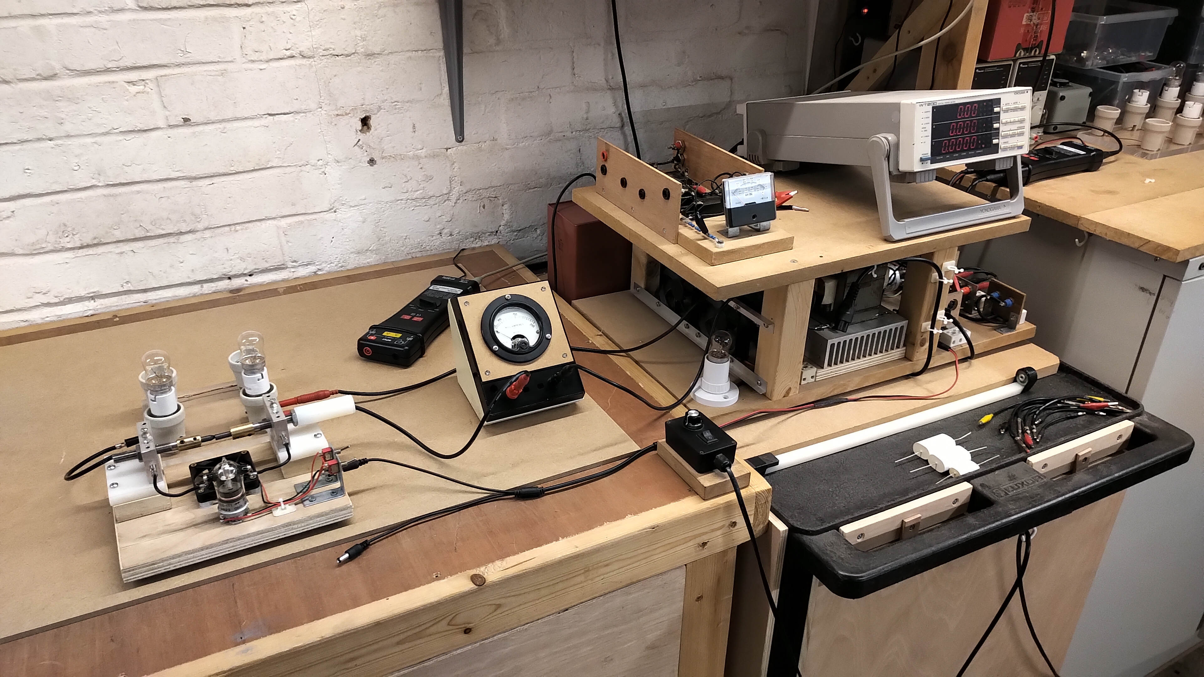
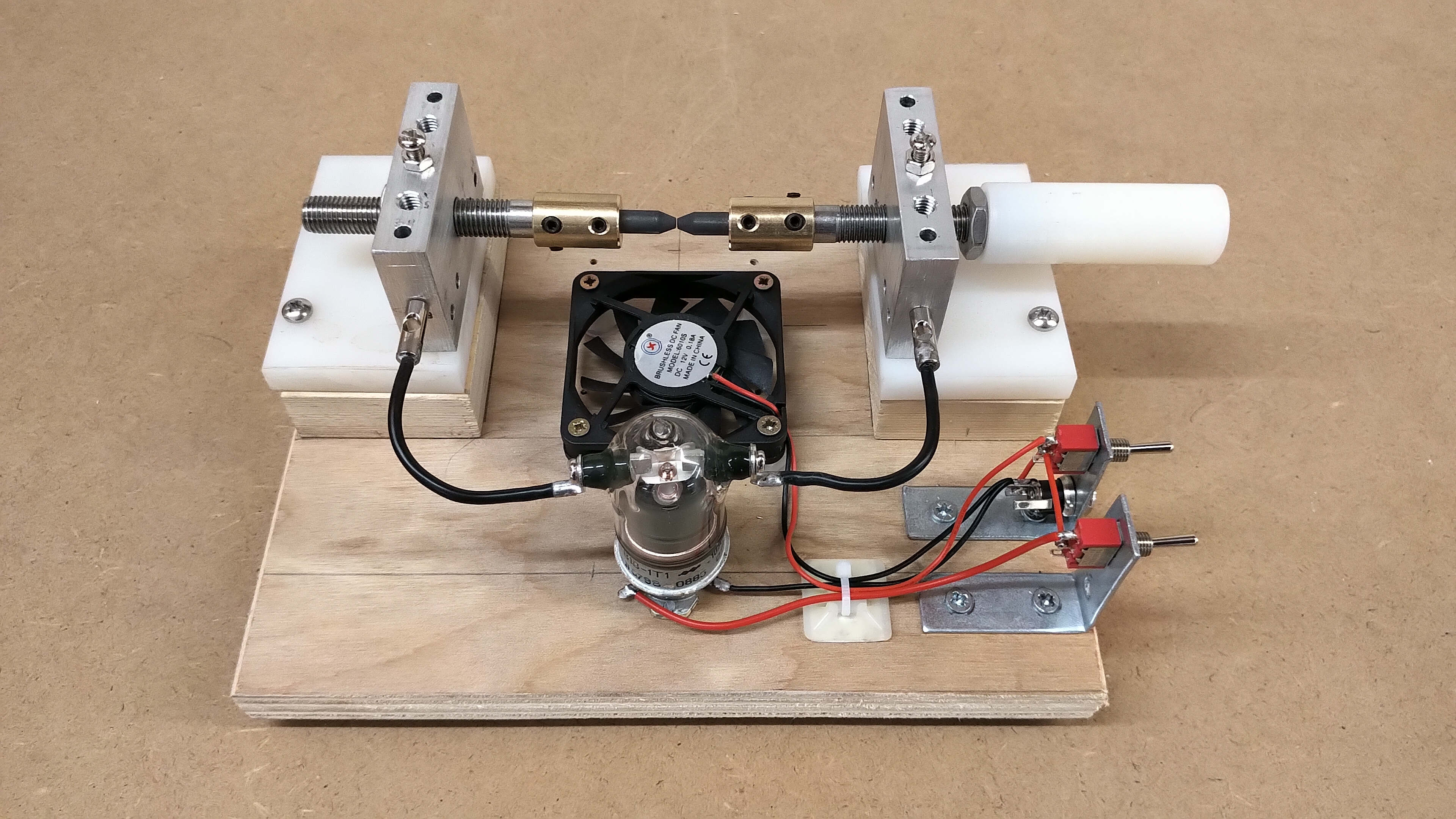
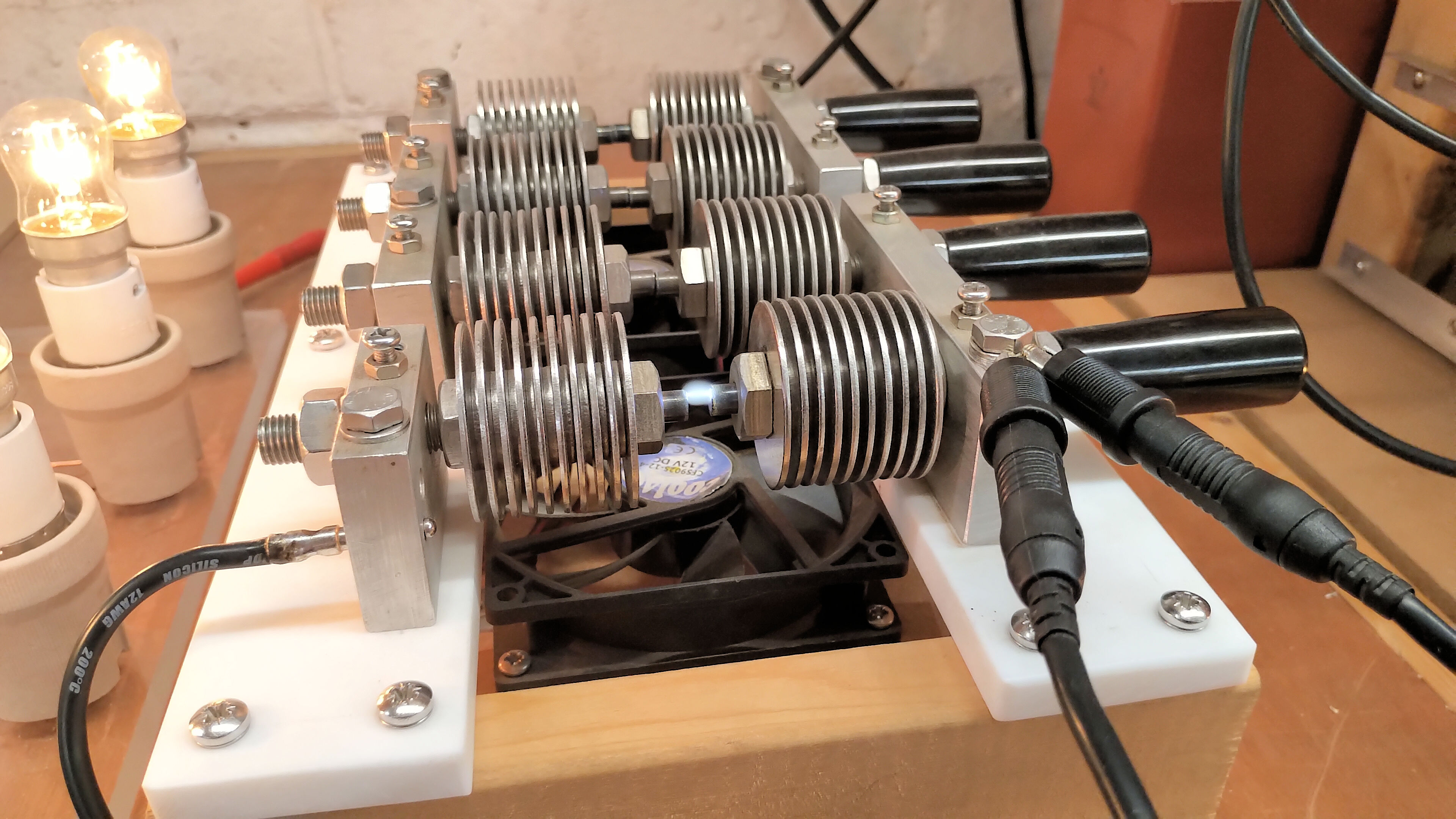
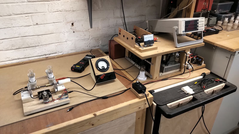
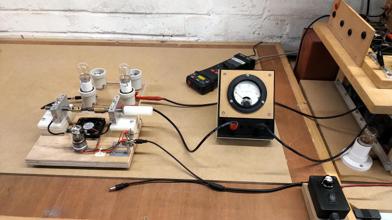
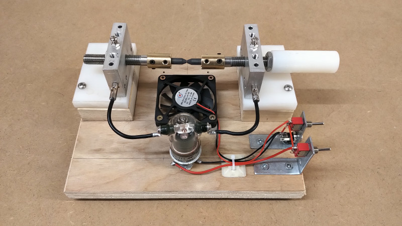
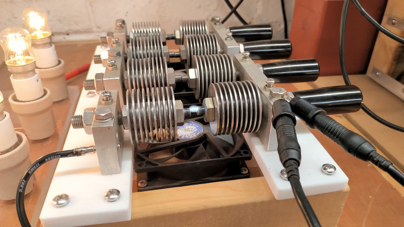
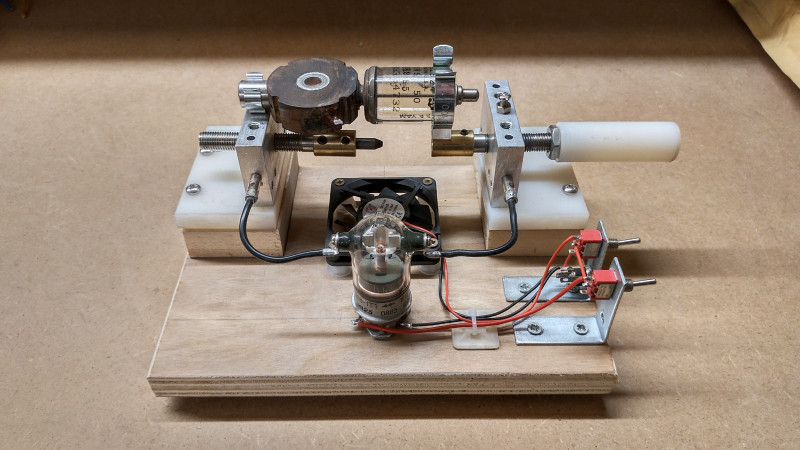
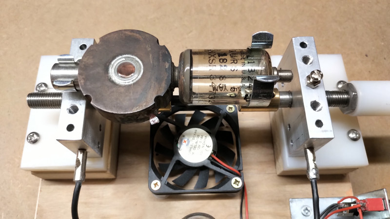
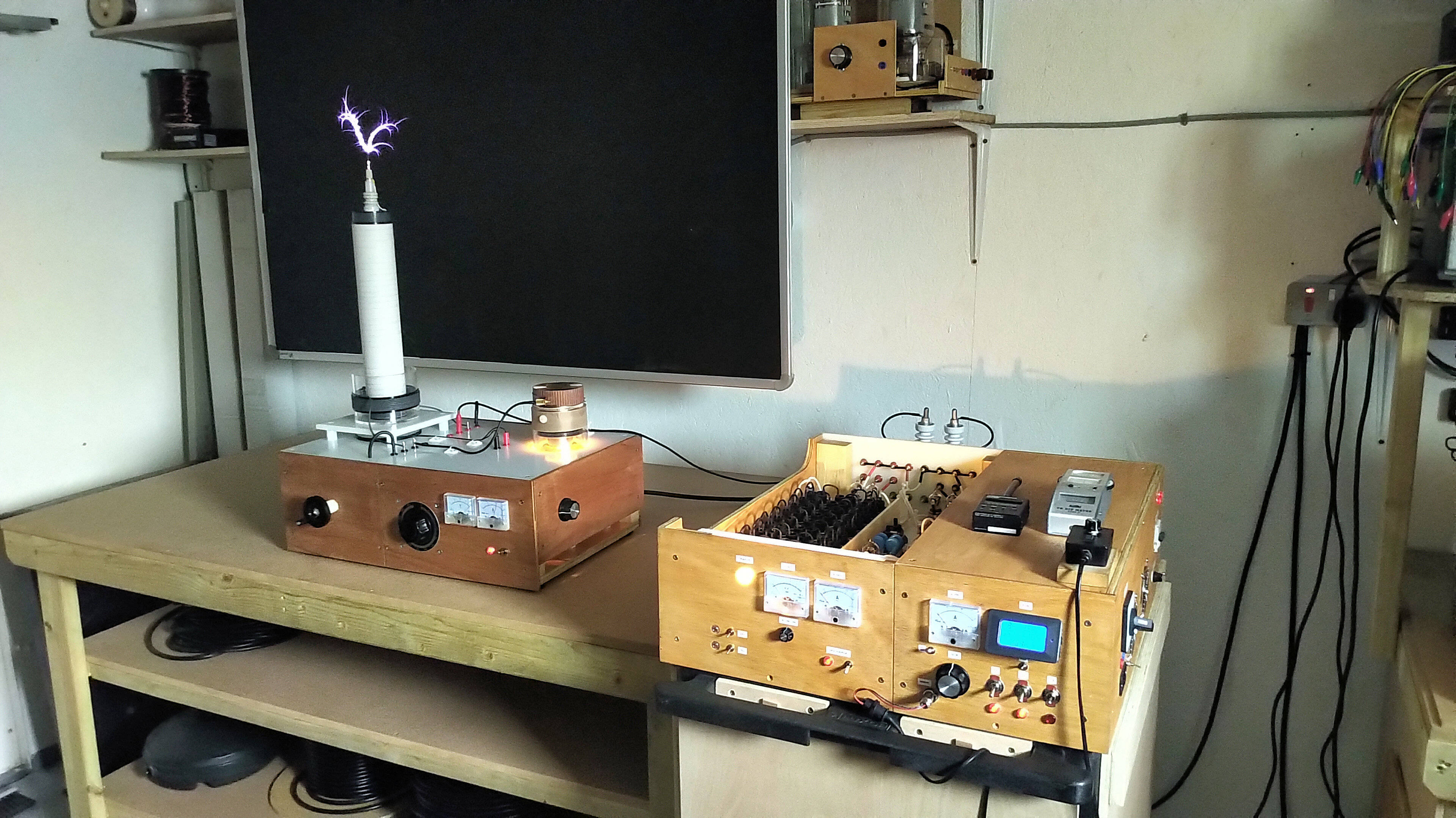
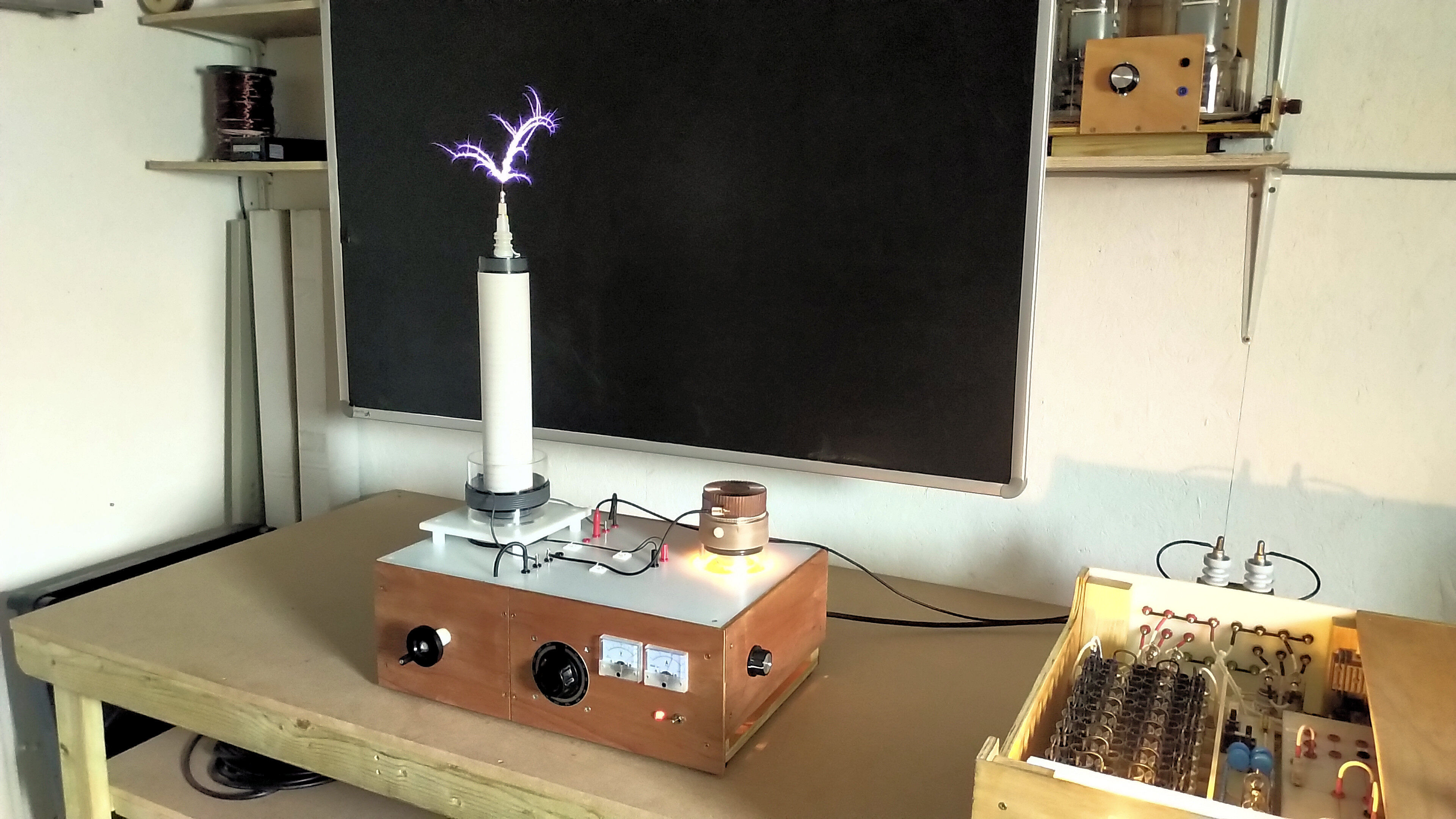
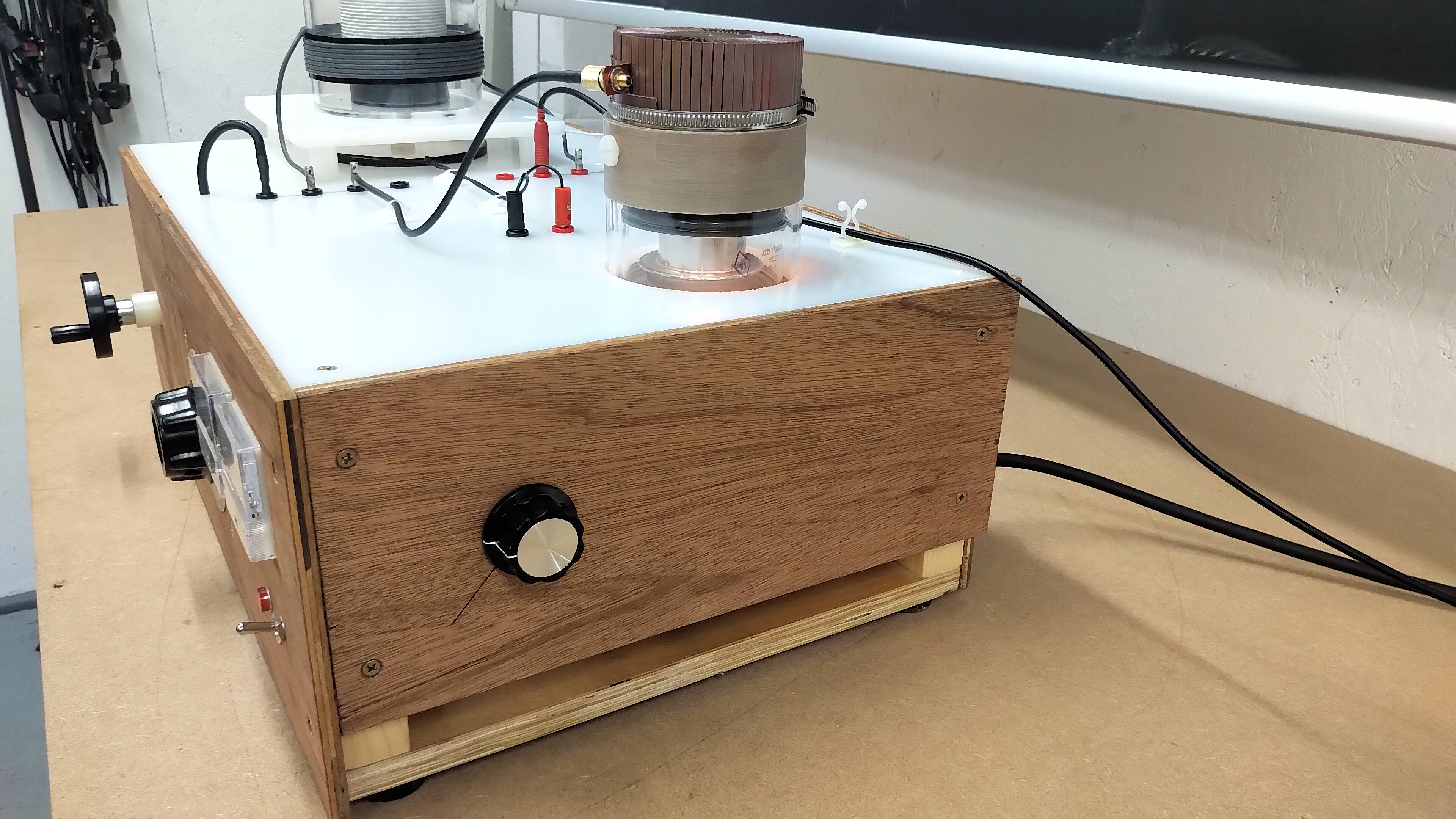
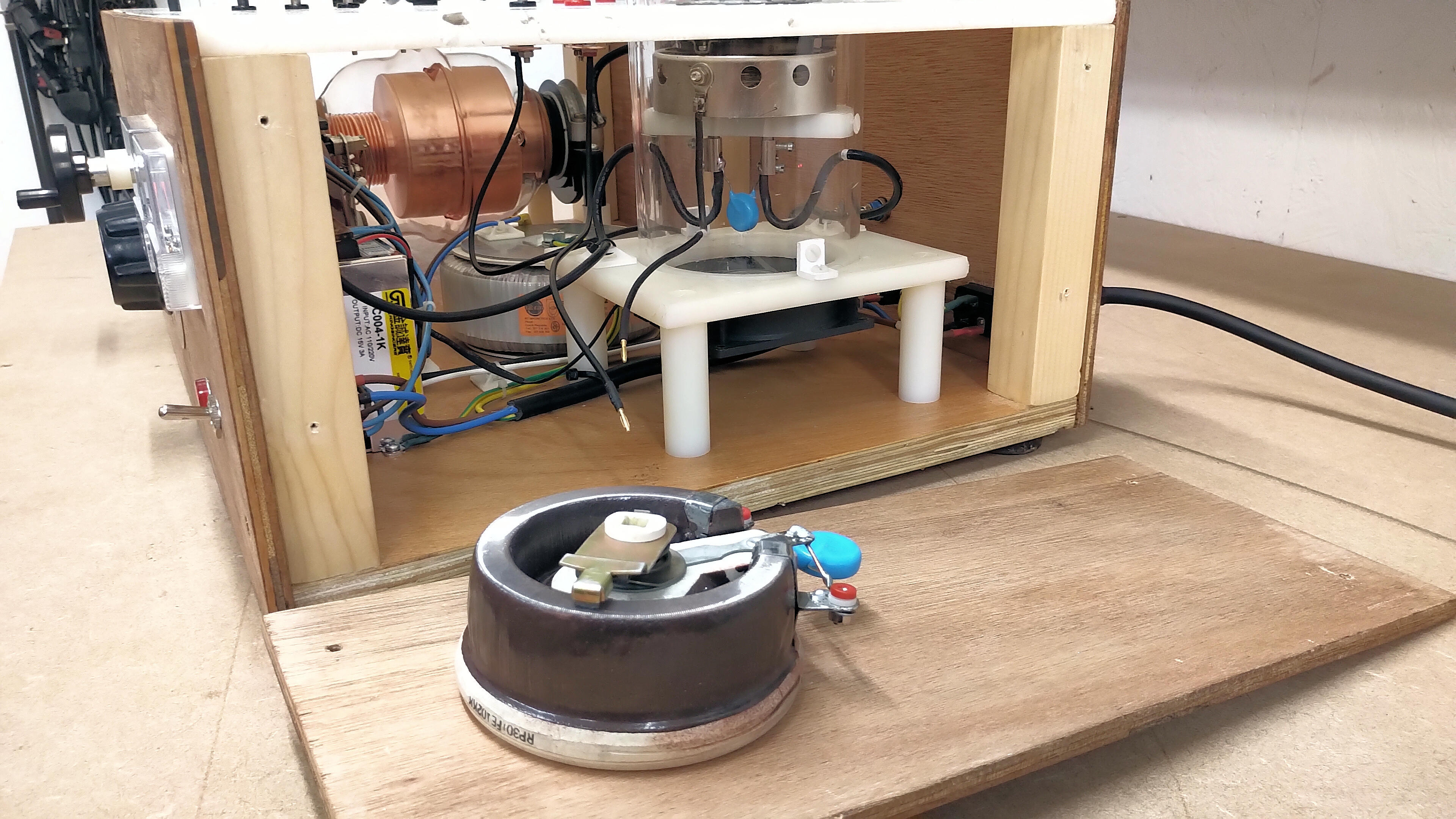
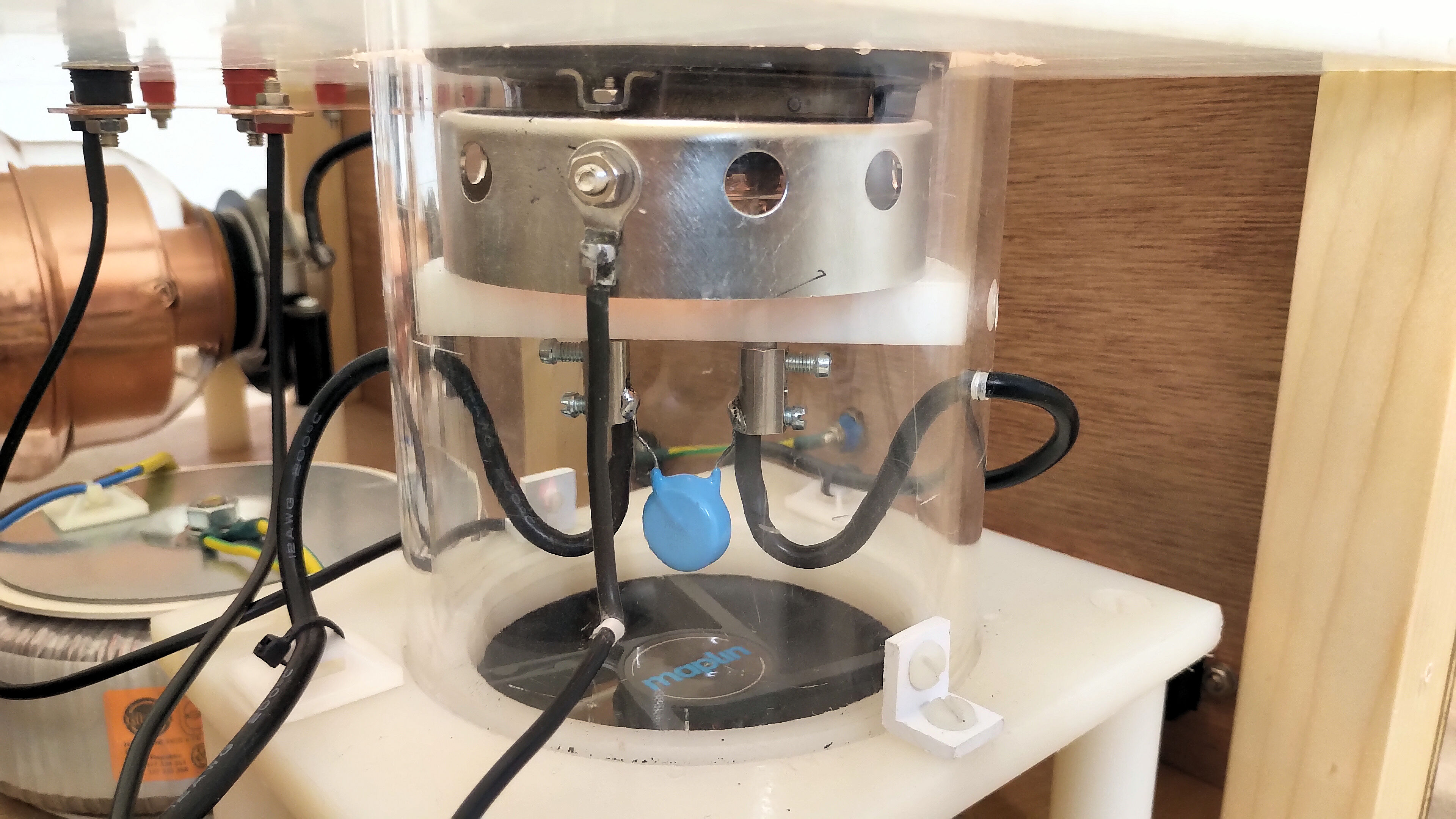
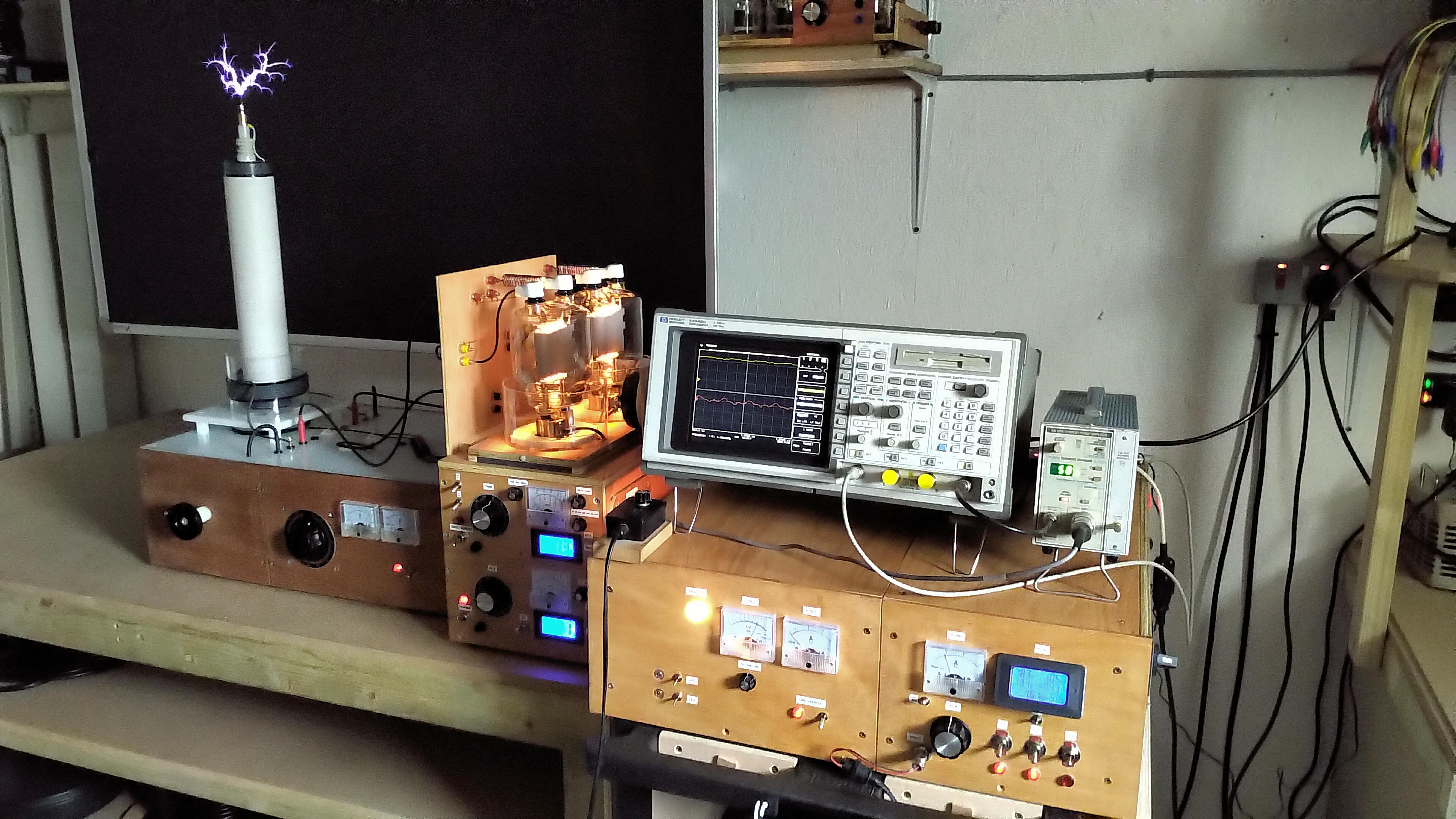
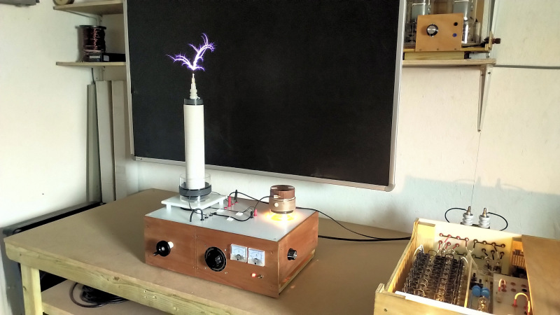
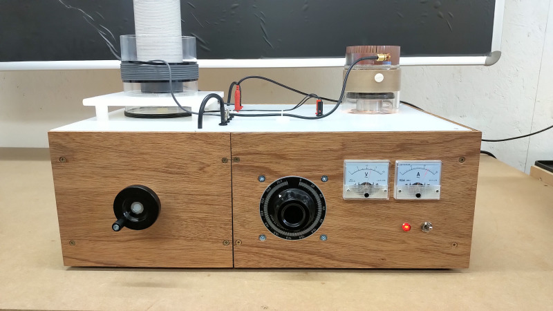
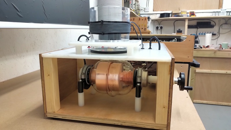
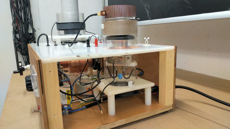
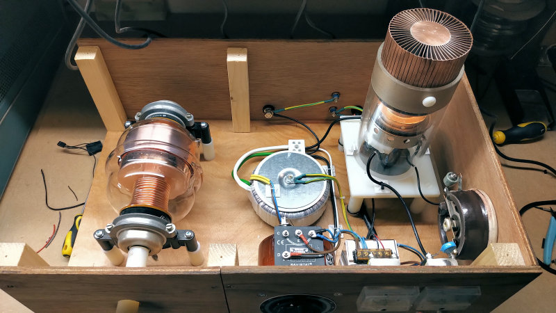
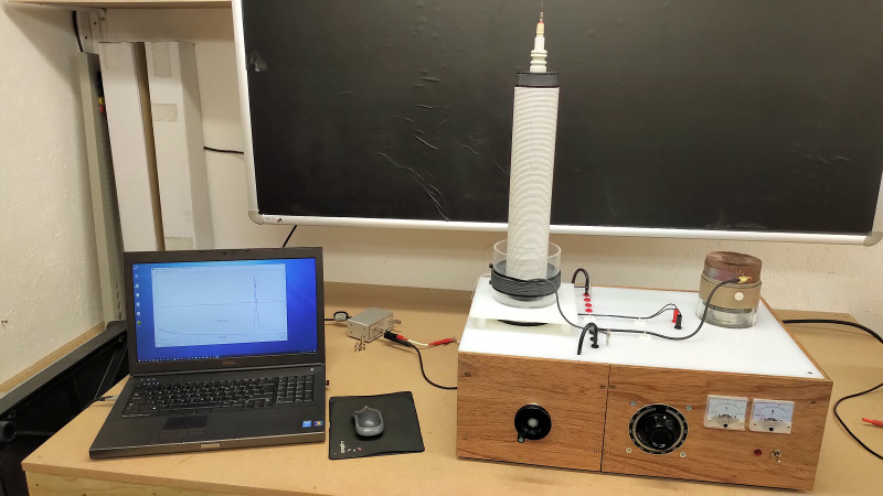
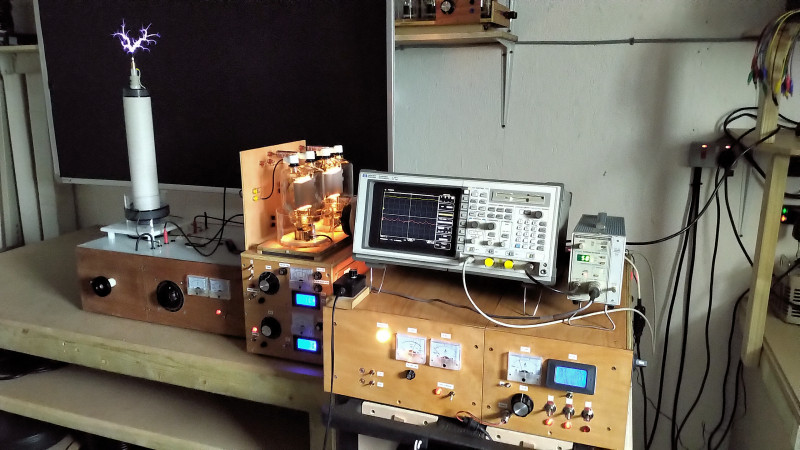
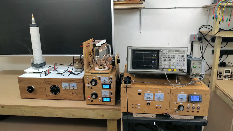
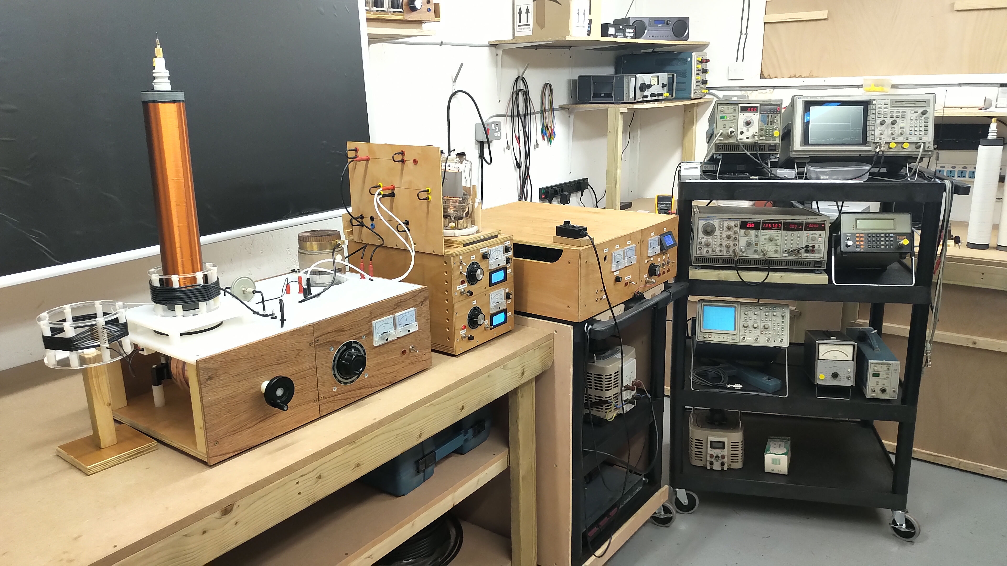
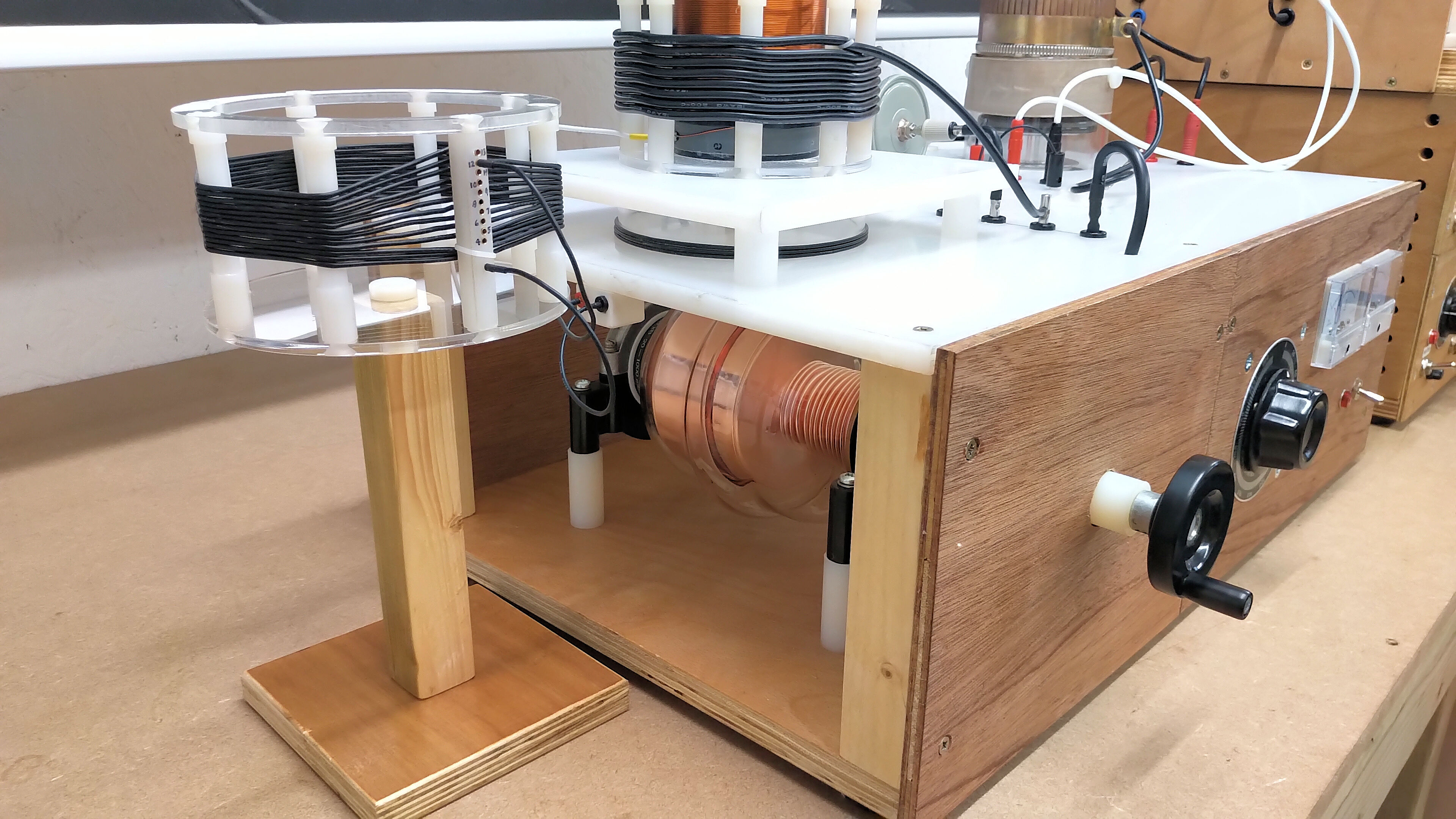
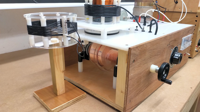
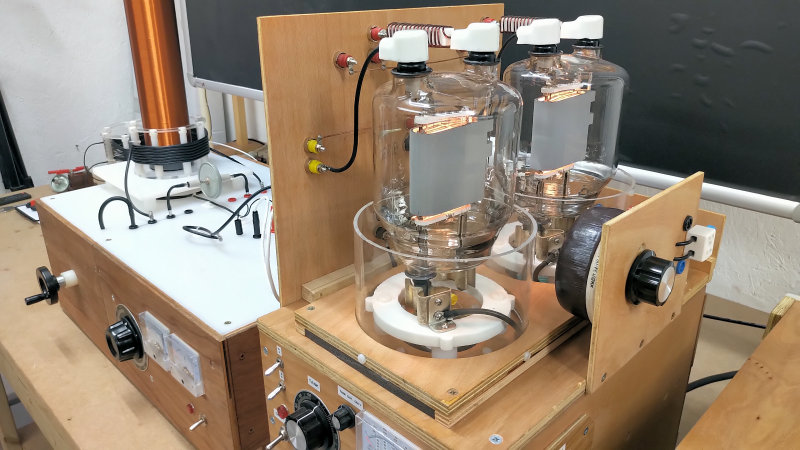
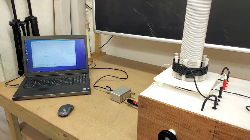
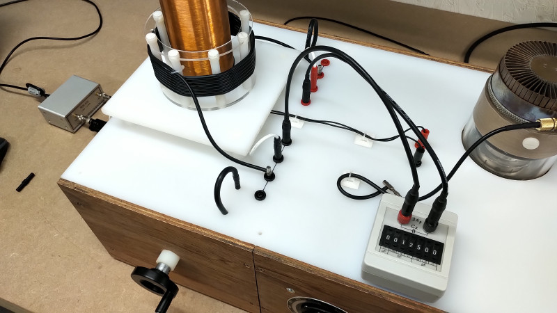
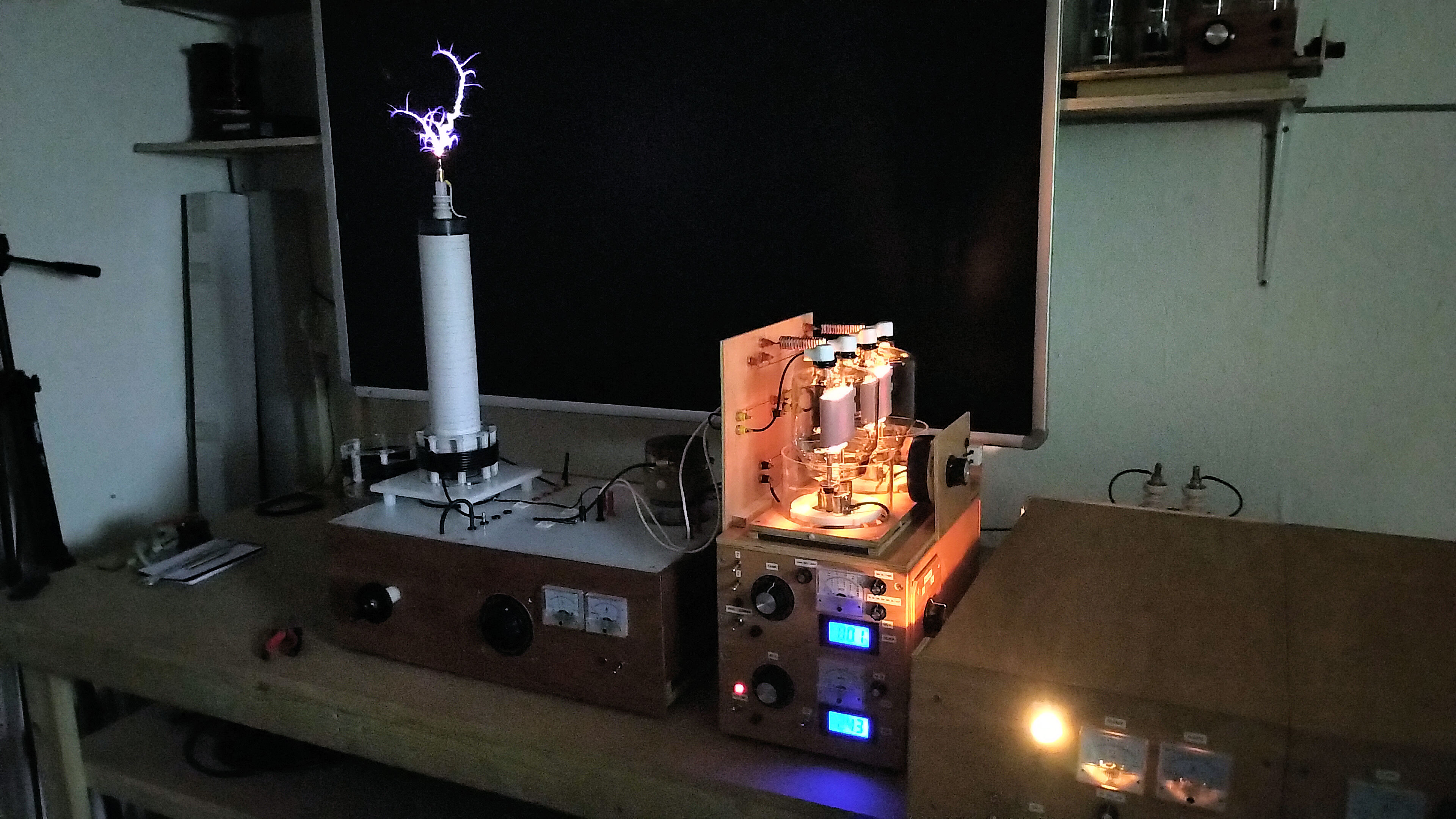
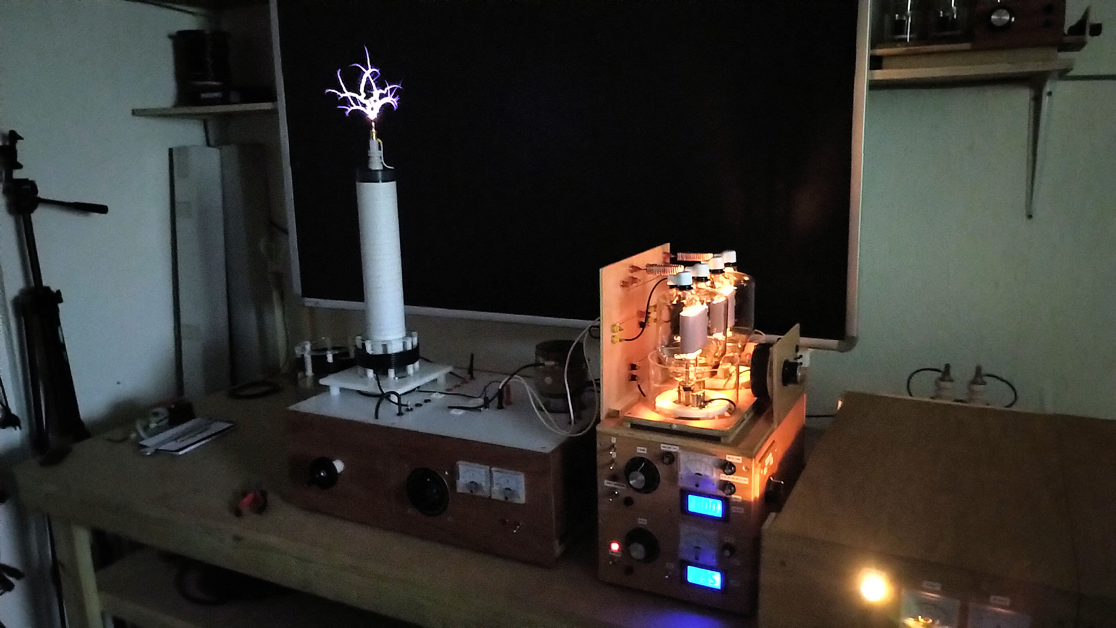
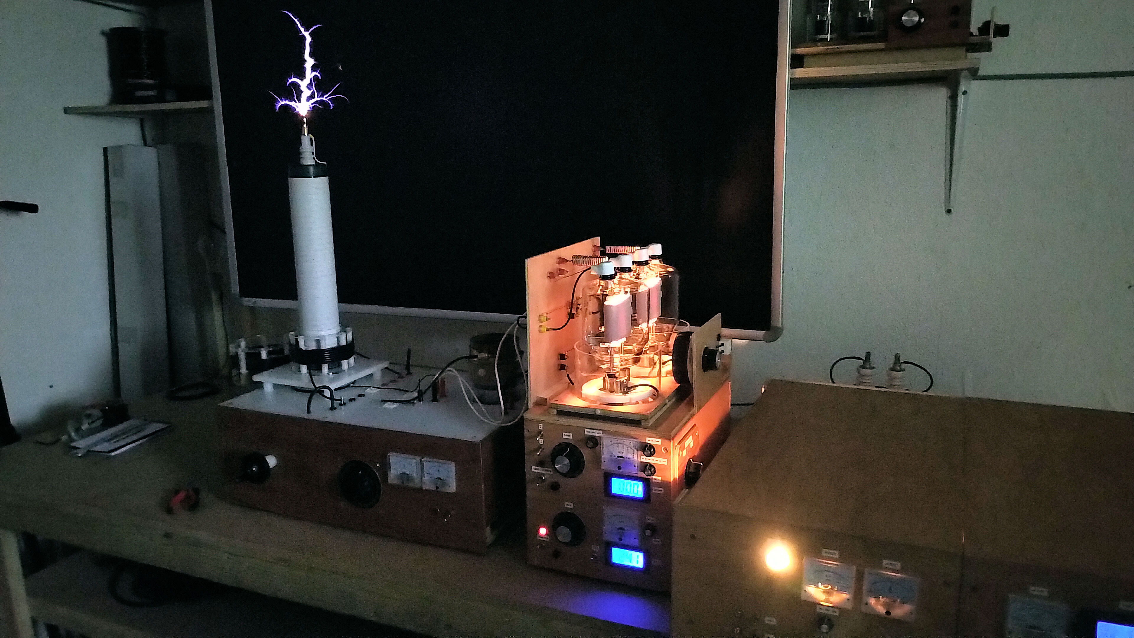
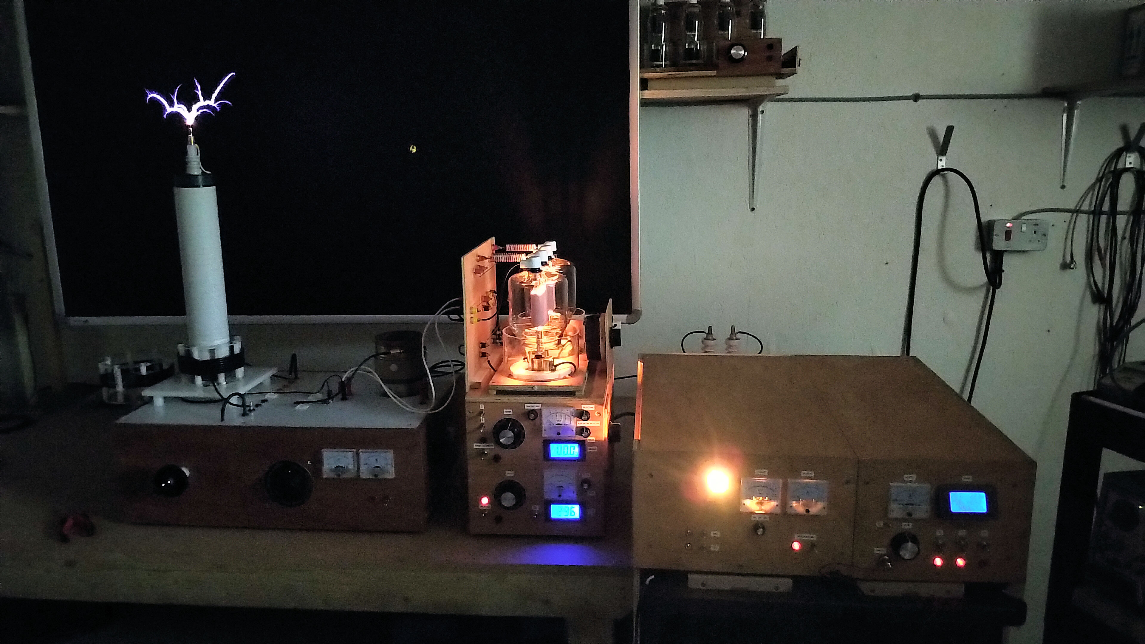
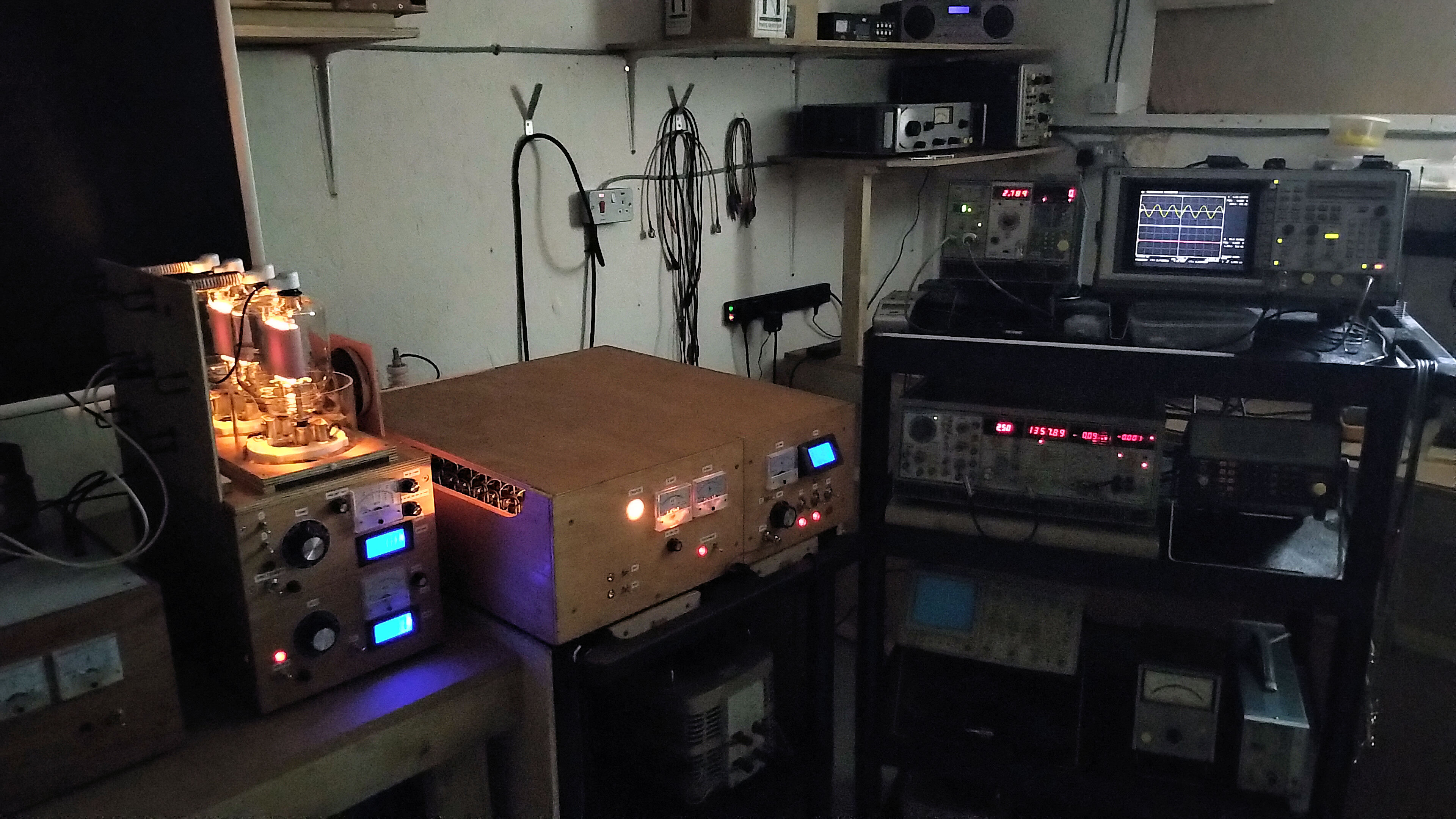
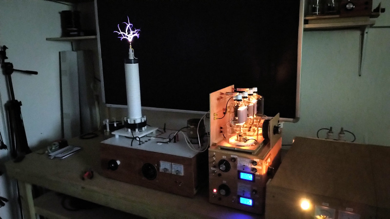
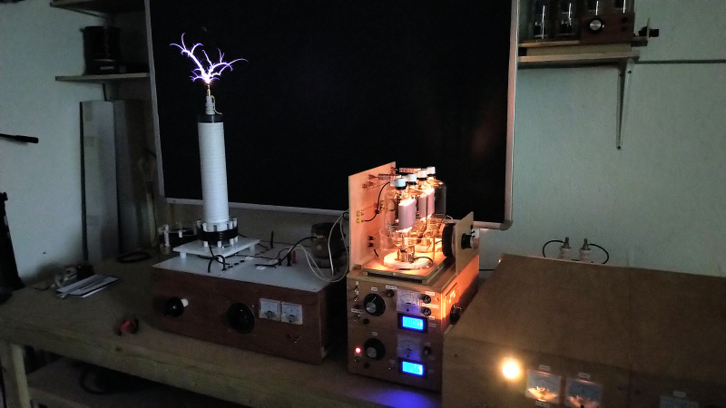
The following video introduces the apparatus, experiments, and phenomena that are most often attributed to Tesla’s radiant energy and matter, and which have been successfully demonstrated in the prior art by researchers such as Dollard et al.[2]. The apparatus used in my video can be readily constructed by a competent electrical engineer,  showing that experimenting and researching this fascinating area is accessible to any open-minded individual with the fortitude to undertake an experimental path of discovery regarding the inner workings of electricity. The video demonstrates and includes aspects of the following:

1. The difference in powering a load with a conventional closed-circuit from the primary coil of a spark gap generator, and a single wire from the Tesla coil secondary.

2. The change in properties observed in the load in a single wire with load position, generator matching, and changes in the single wire cavity length.

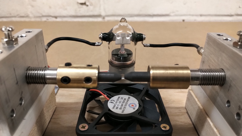
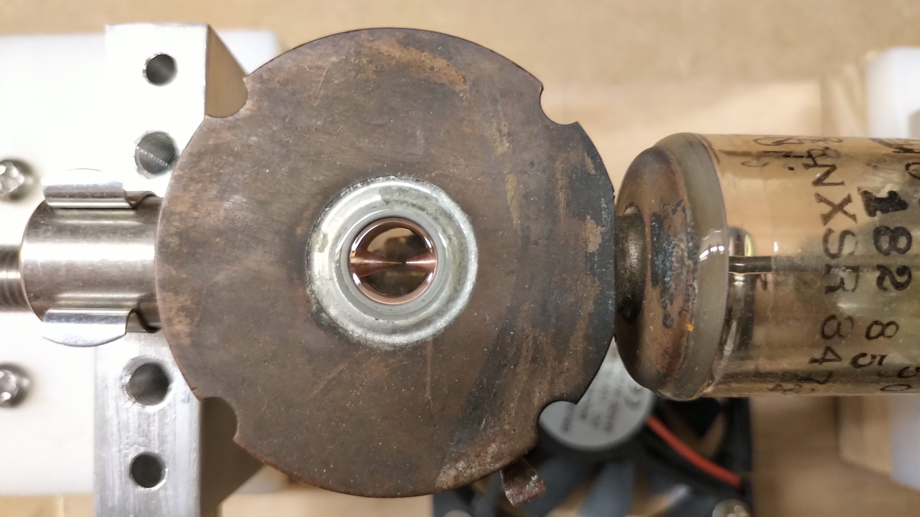
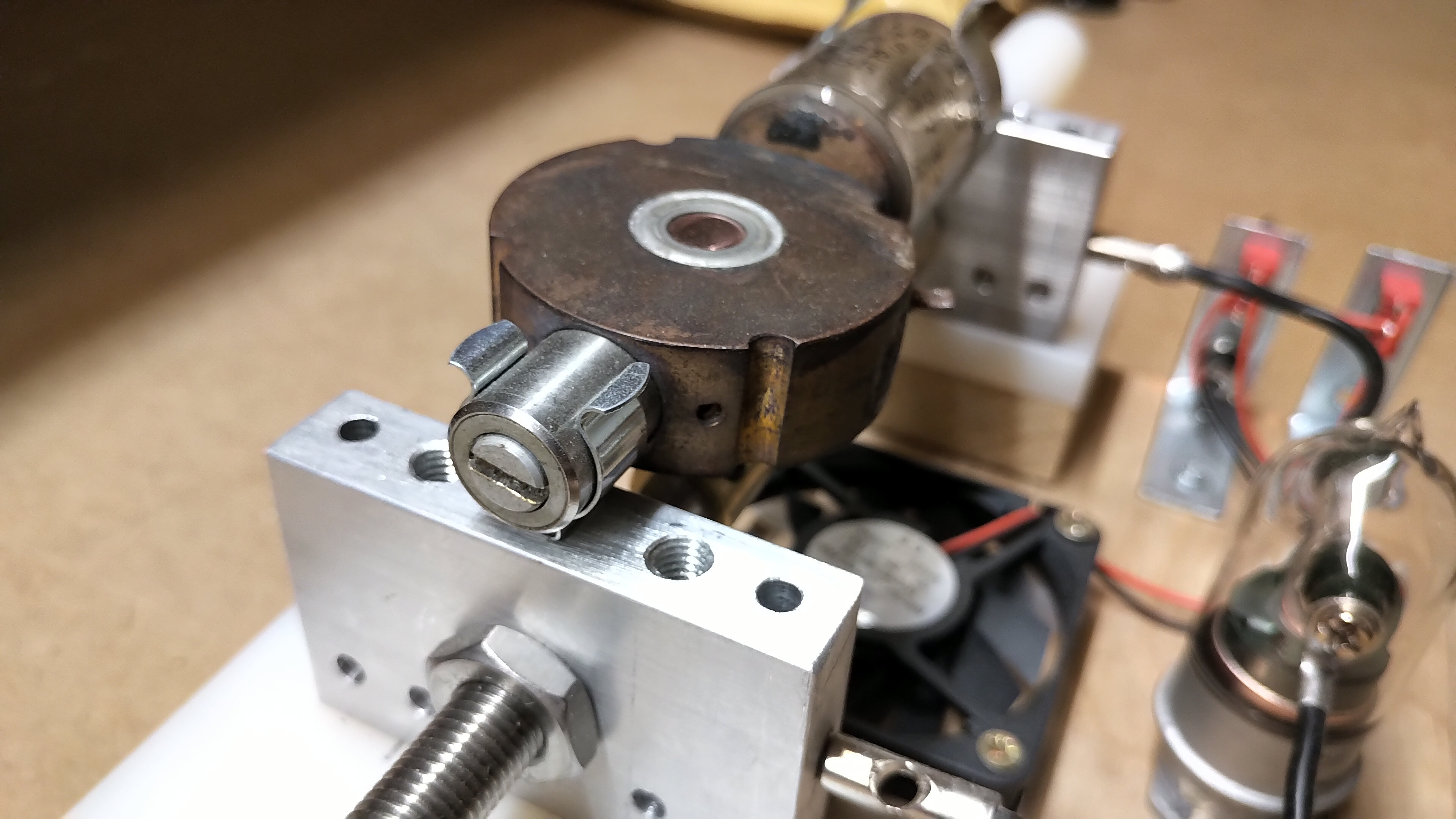
3. The force exerted on different materials as a result of radiant energy/matter emanating from an incandescent lamp emitter in the single wire load.

4. The different responses of materials to radiant energy emanating from the lamp emitter.

5. The radiant matter pressure wave emanating from the lamp emitter, as experienced by the human hand.

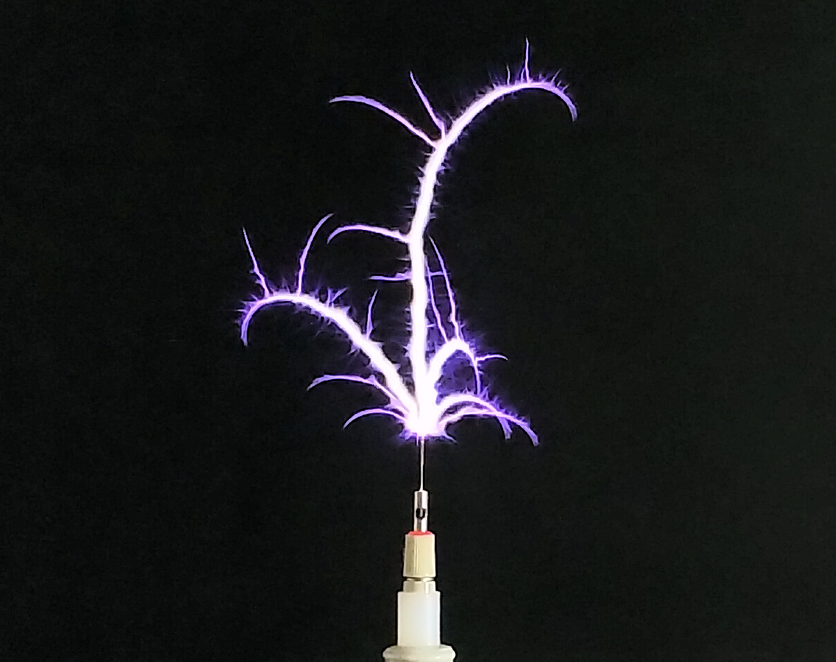
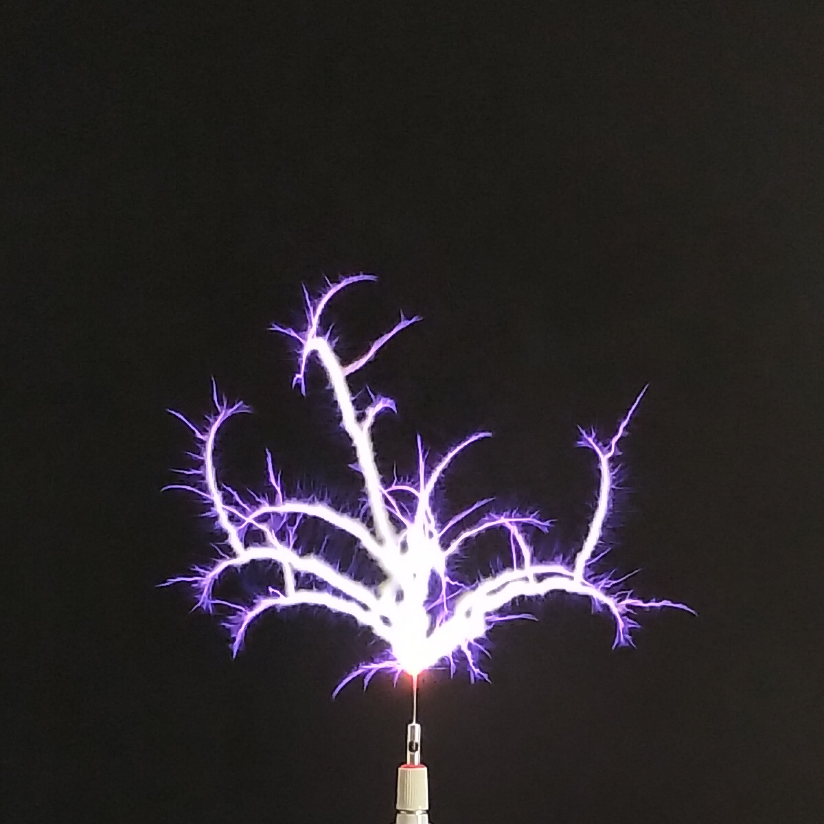
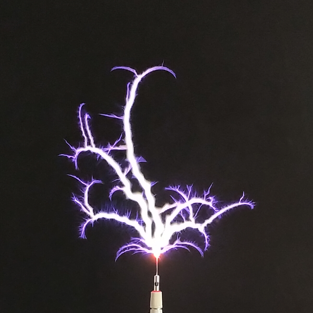
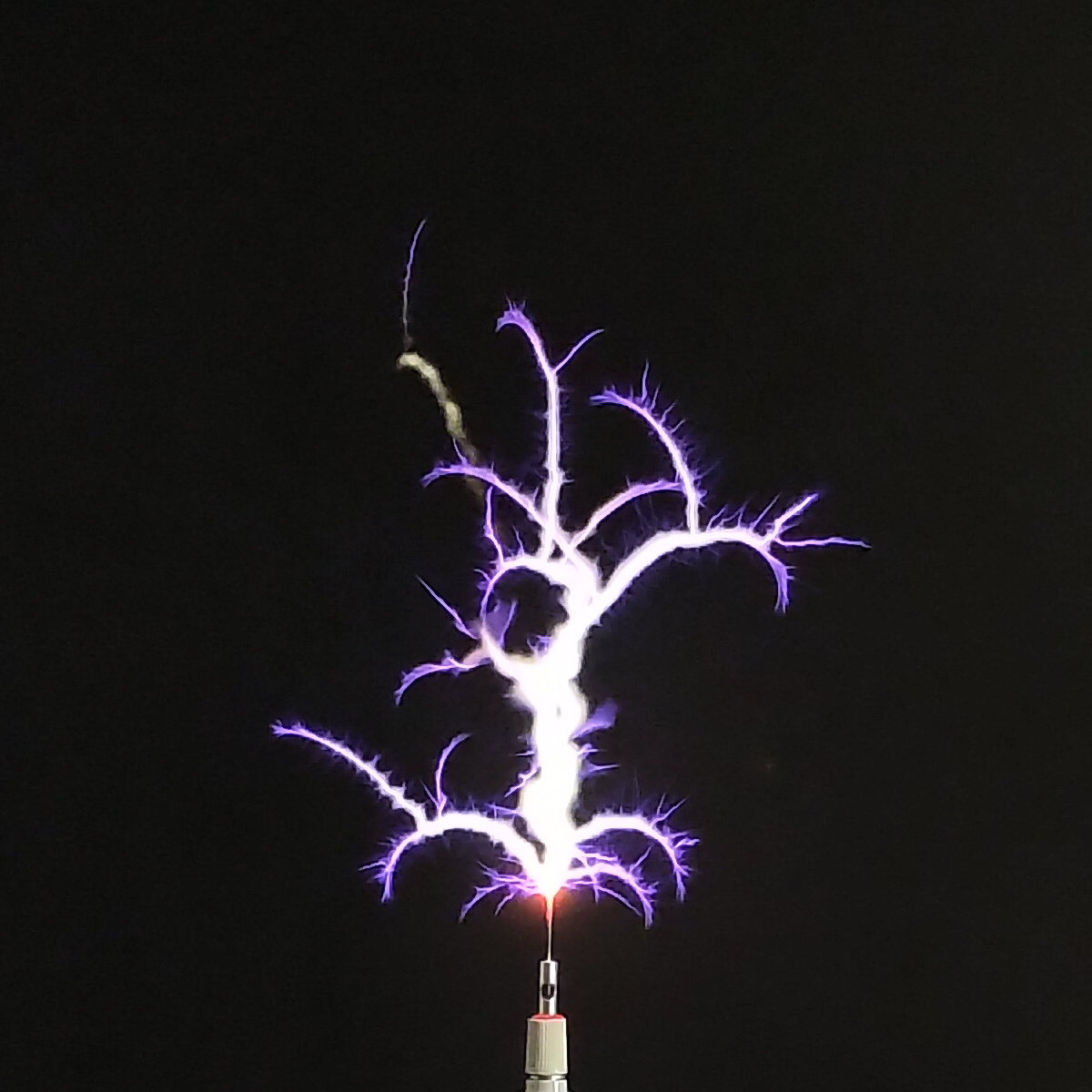
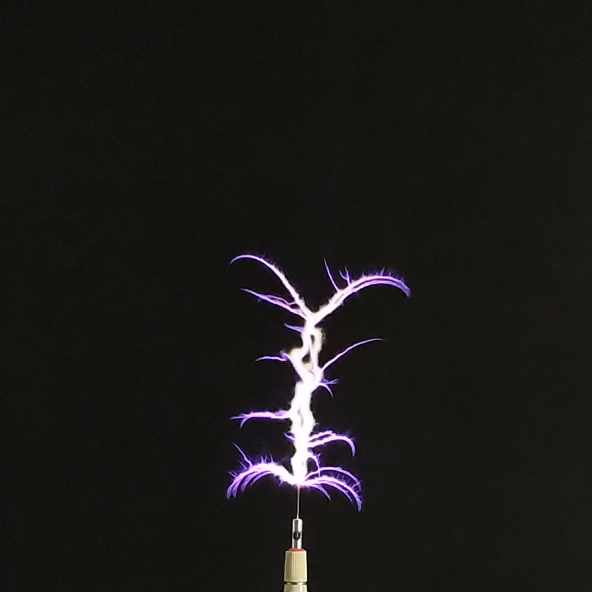
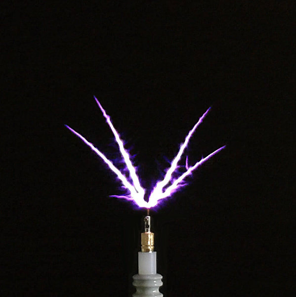
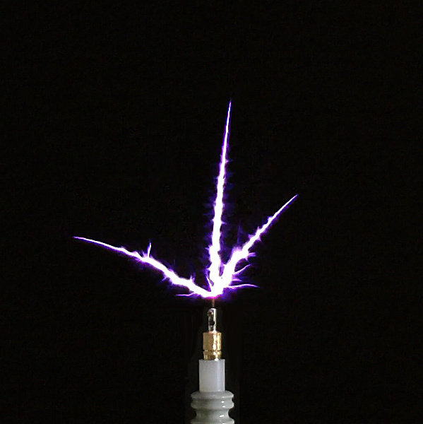
6. Discharge “plasma-like” emanations directly from the lamp emitter to the surrounding medium.

7. Vibration and physical movement stimulated in the lamp filaments when radiant energy interacts with another object in the surrounding medium.

8. Cool lamp glass temperature when emanating considerable light from the lamp emitter, a so-called “cold” electricity phenomenon.

9. Radiant energy charging of a capacitor, accompanied by subsequent discharge in a neon lamp load, showing a “cool” white-bluish discharge, and a violent snapping sound.

10. An initial consideration of the inter-relationship between the longitudinal and transverse modes of electricity in the single wire load.

11. The transformation of energy from the longitudinal mode to the transverse, and the dissipation of this energy as power in the single wire load.

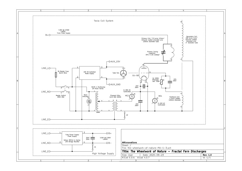
Figure 2 below shows the schematic for the generator and experimental apparatus used in the video. The high-resolution version can be viewed by clicking here.

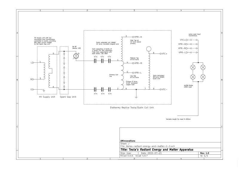
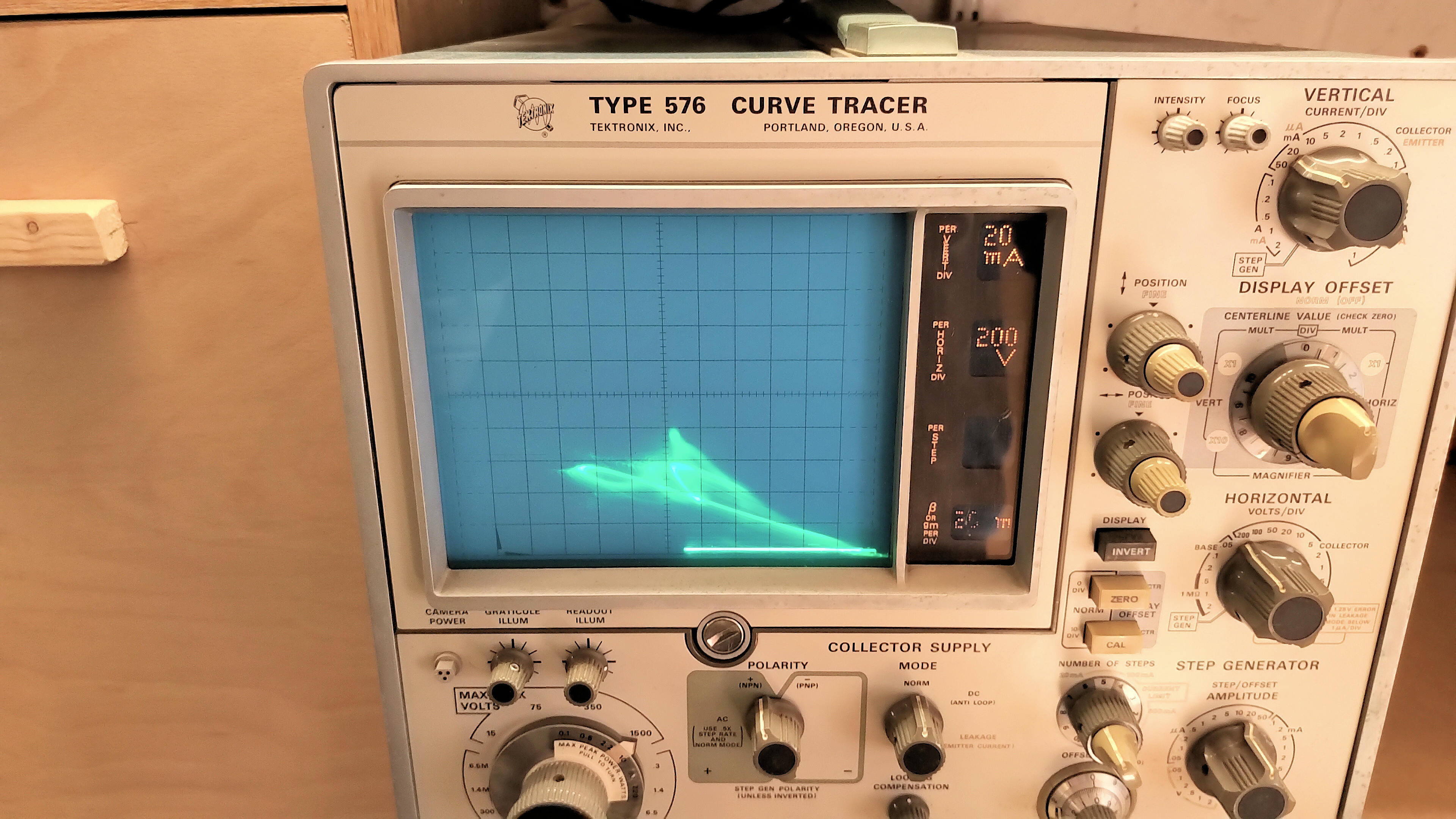
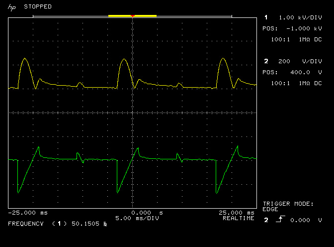
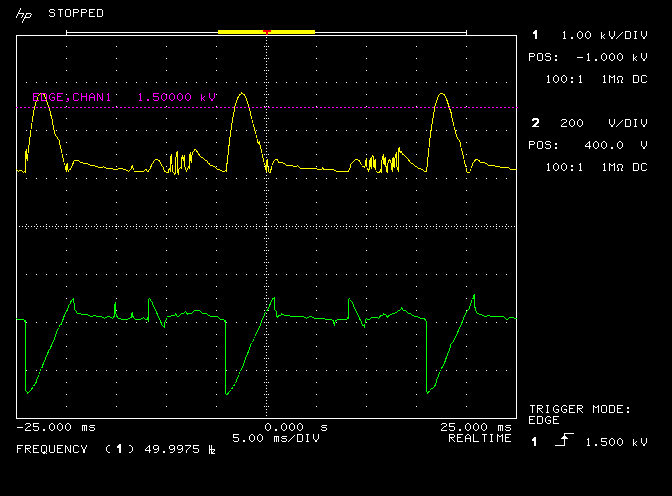
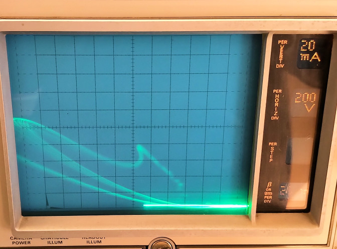
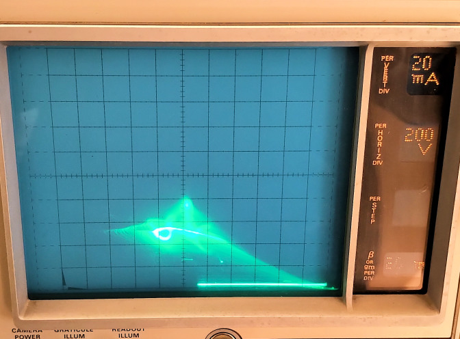
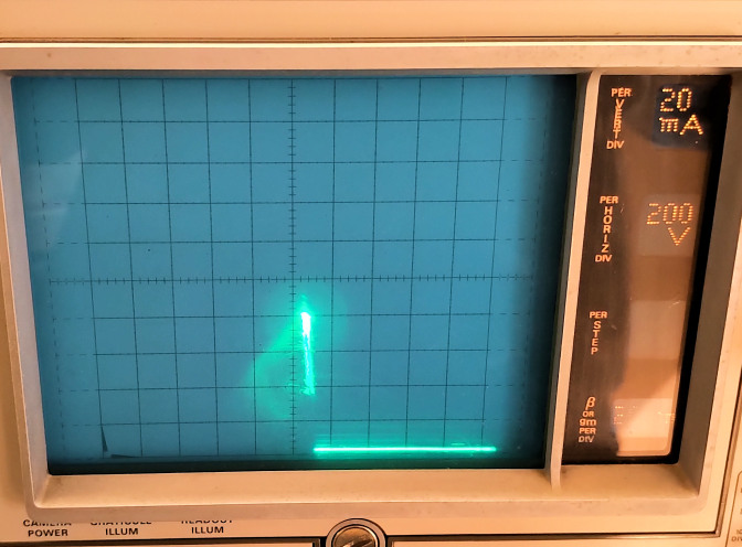
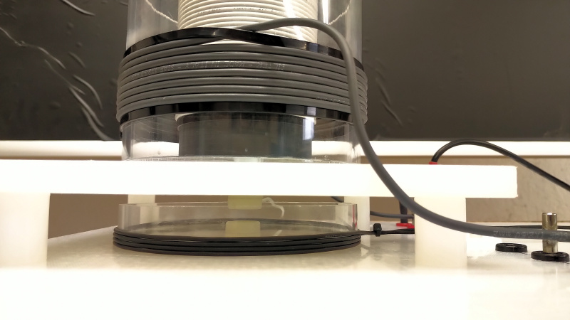
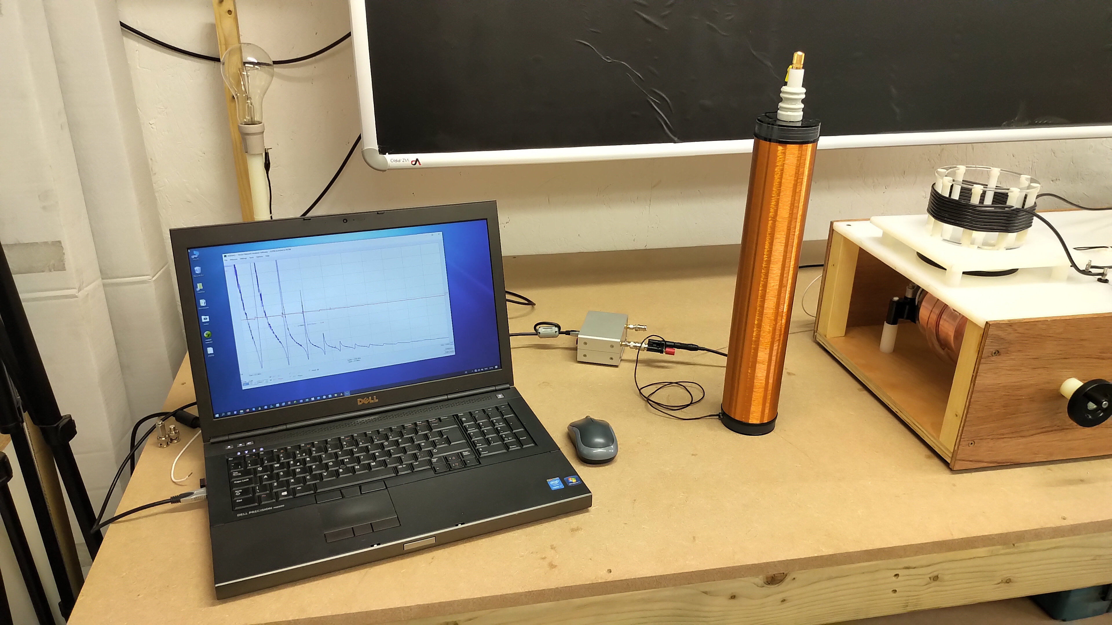
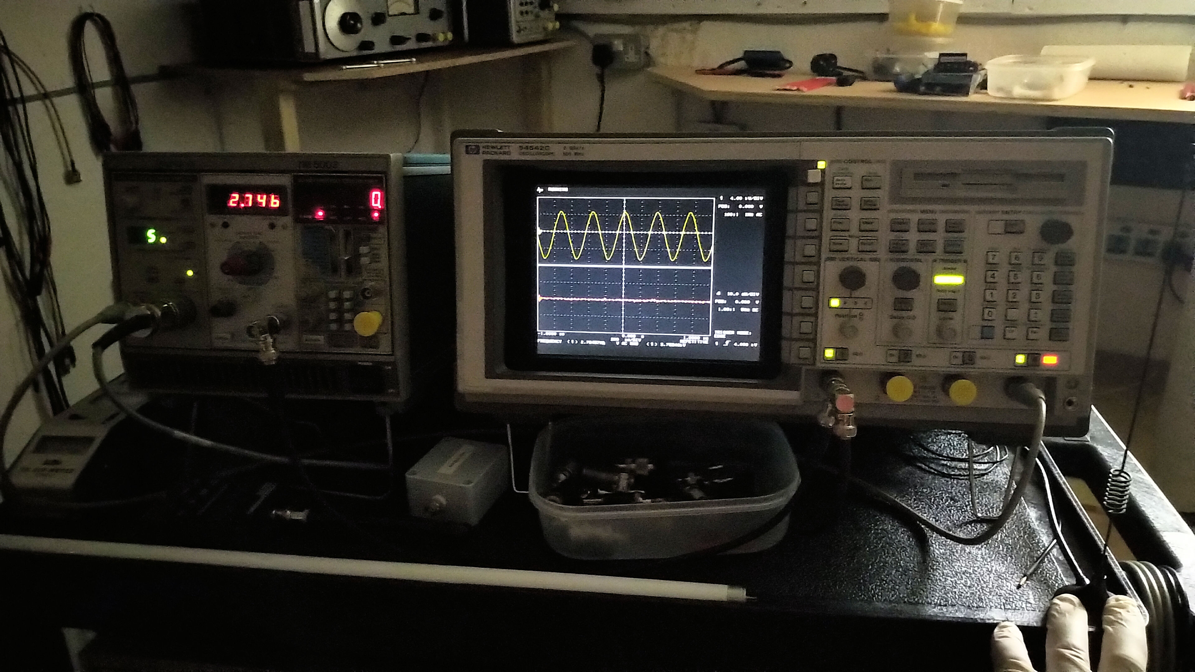
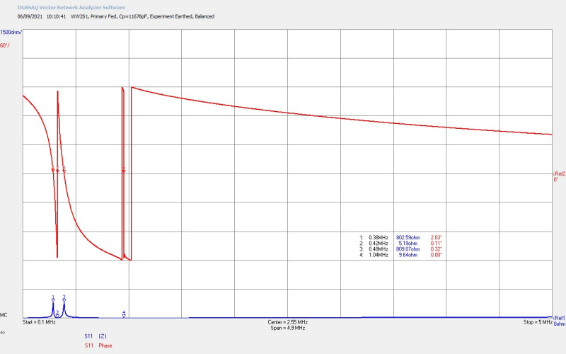
Figure 3 below shows the secondary pulse burst at the single wire load measured using a 40kV high voltage probe whose input terminal is placed closed to the load via a short fly-lead. The fly-lead was initially connected directly to the load but caused some interference and erratic operation to the measurement equipment, as shown in the video. This erratic operation results from transient current spikes induced directly through the probe connections to internal circuitry, and cross-coupled amongst the various earth connections in the equipment line-supply. Individual ferrite chokes can be used on the measurement instrument line supply cables to prevent this undesirable cross-coupling. In this case the fly-lead of the probe was simply disconnected from the load but left in close proximity to the measurement region, which had no detectable impact on the measured results, but sufficiently reduced the unwanted interference to allow for correct instrument operation.

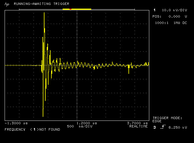
It can be seen from the secondary pulse burst that transients in the single wire during the initial spark discharge are large in amplitude, (up to 40kV in voltage magnitude, and 100s of amps in current magnitude), and resemble impulse-like spikes with very short life-times, densely packed in time, and with very short duty cycles. These transient impulses give rise to both sinusoidal oscillations in the resonant circuit of the secondary, and as expected for a Tesla coil or TMT apparatus, stimulate generation of the characteristic longitudinal wavefronts in the cavity of the secondary circuit. As considered in previous posts, the longitudinal wavefronts themselves could result from the coherent spatial inter-action between the electric and magnetic fields of induction in the LMD mode, and where the coherent aspect is the direct consequence of underlying displacement events.

It is conjectured, and explored here, that high-energy transient impulses, that are ideally unidirectional in nature, and characterised by very large amplitudes and very short life-times, stimulate through non-linear processes electrical events or an imbalance in the system that needs to be, and can only be, rebalanced by the underlying coherent process of displacement. The product of this momentary exposure to displacement, (or an inner-working of electricity), is emission of the rays or beam-like emanations Tesla referred to as radiant energy, which in-turn give rise directly to the unusual electrical phenomena observed in the experiment. It is to be conjectured that the observed radiant energy emanations are directly the consequence of a displacement event taking place in the non-linear dynamics of the local electrical system.

With this conjecture stated the various experimental observations shown in the video will now be considered with the objective of determining their possible source or cause, and in order to get a better qualitative understanding of the underlying principles and processes involved. It should be noted that real experimental results, observations, and perceptions are being conjectured here into a possible underlying explanation, which will need considerable further consideration and experimentation to test, verify, and draw reliable and robust conclusions as to the validity of the considered conjecture.

Transference of electric power in closed and open-circuit systems

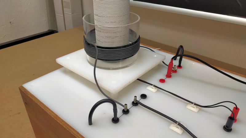
The dissipation of power in an “open-circuit” or single wire load is a very characteristic phenomena which can be readily observed and measured in almost any Tesla coil geometry and configuration. A suitable resistive load such as an incandescent lamp can be made to illuminate brightly when connected by a single terminal to either end of the Tesla coil, and the other terminal of the lamp has a small wire extension or fly-lead added. Without this fly-lead the lamp is at the very termination of the single wire and it will not illuminate or dissipate power.

This single wire power dissipation can be observed irrespective of how the Tesla coil primary is energised, whether it be from a sinusoidal linear amplifier or oscillator, a burst discharge from a spark gap, or a pulse generator. In other words, provided the primary and secondary coils are arranged to couple sufficient energy between them it does not matter whether this energy is from a single frequency linear sinusoid, a burst discharge envelope, or a set of non-linear transients, pulses, or impulses, it is possible to dissipate this coupled power within a resistive load placed in the single wire extension of the secondary coil.

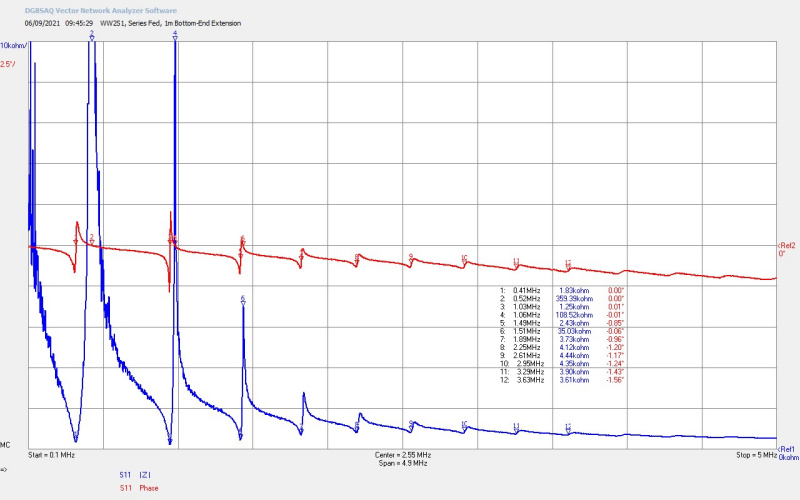
It can be seen in the video that the lamp load could not be made to illuminate when connected to output taps on the primary side of the Tesla coil, even on the “HI” Oudin extension terminal. The tension on these primary side terminals is high, about 1kV on the LO, 2-4kV on the MID, and up to almost 10kV on the HI terminal. There is also a wide range of frequencies in the pulse burst due to the spark discharge in the primary circuit, so the output of these primary terminals is certainly a high tension RF burst discharge. This RF burst looks very similar in envelope shape and structure to that measured in the secondary, with the major exception that the oscillation within the burst envelope is dominated by the primary circuit characteristics, whereas in the single wire it is dominated by the secondary coil circuit characteristics.

Given all of this the lamp load will not illuminate and dissipate power when connected by a single wire extension to the primary side terminals, and yet will readily illuminate when connected by a single wire extension to the secondary coil. The only way found to illuminate the load when connected to the primary side terminals is to complete the circuit by connecting the single-wire extension back to the primary ground terminal, making a normal closed-circuit system.

A very similar example to this would be powering an incandescent lamp when placed across the output terminals of an oscillator, or even better in the coaxial transmission line between the output of an amateur radio transmitter tuned to transmit say in the 160m HF band (~2 Mc), and a half-wave dipole antenna at the far end of the coax. When the coax is connected on both terminals (circuit-closed) the lamp will light and dissipate some of the power from the transmitter dependent on the impedance it presents within the circuit, with the remaining power being radiated from the antenna and consumed by the coax. When either terminal of the coax is removed (open-circuit) the lamp will not light and no power is dissipated in either the lamp, or delivered to the antenna.

This most simple, and yet profound difference, between powering a load from the primary and secondary circuits of a Tesla coil, where both coil outputs are high tension and contain considerable RF energy, suggests a fundamentally different mechanism of electrical transmission and/or dissipation of power in the two cases. In the primary the system behaves exactly as one would expect for a conventional electrical circuit, and can be measured and calculated precisely in the case where a linear sinusoid is applied to the circuit. If we reduce all electric circuit characteristics to the inter-dependent relationship of the electric (or dielectric) field of induction (Ψ), and the magnetic field of induction (Φ), and their inter-action with material type, form, and structure, then it should be clear that there is a fundamental difference in the relationship, or mode of inter-action, between these two induction fields within primary circuit and the secondary circuit.

In the closed-circuit case the configuration of Ψ and Φ lead to voltages and currents distributed in time around the circuit that are transverse in nature and where the phase relationship between them is distinctly defined by the impedance elements, (boundary conditions), distributed in the overall system. In this case or mode Ψ and Φ are fully differentiated, non-coherent, not in-phase either spatially or temporally, and only becoming temporally in-phase in the transverse electro-magnetic (TEM) mode for far-field propagation.

In the open-circuit or single wire case and to dissipate power in a load it is necessary for the configuration of Ψ and Φ which are still fully differentiated, to be coherent, that is in-phase spatially and temporally. This can be accomplished through the longitudinal mode, or the LMD  mode as it is known, where both Ψ and Φ are locked in phase alignment with each other, and form a combined traversing wavefront within the cavity, generating an electrical pressure wave ahead of the combined wavefront.

In this case local changes of impedance on the single wire, such as the filament of a lamp, lead to power dissipation at the pressure wave through local generation of instantaneous voltages and currents within the impedance change, and hence power dissipation, light, and heat. It can be seen that rms current decays in magnitude along the length of an open-circuit terminated single wire longitudinal cavity, rather than stay constant as would be expected for a transverse mode circuit. With the lamp as the termination of the single wire cavity it will not light as the local current in the wire end has reduced to zero, and no power can be dissipated in the load in the transverse mode.

In summary for now, the most basic Tesla coil presents a fundamentally different power transmission mode at the secondary coil, that is irrespective of how it is energised in the primary circuit, and is most likely longitudinal in nature, and results in the phenomena of single wire transmission of power.

Attractive and repulsive forces

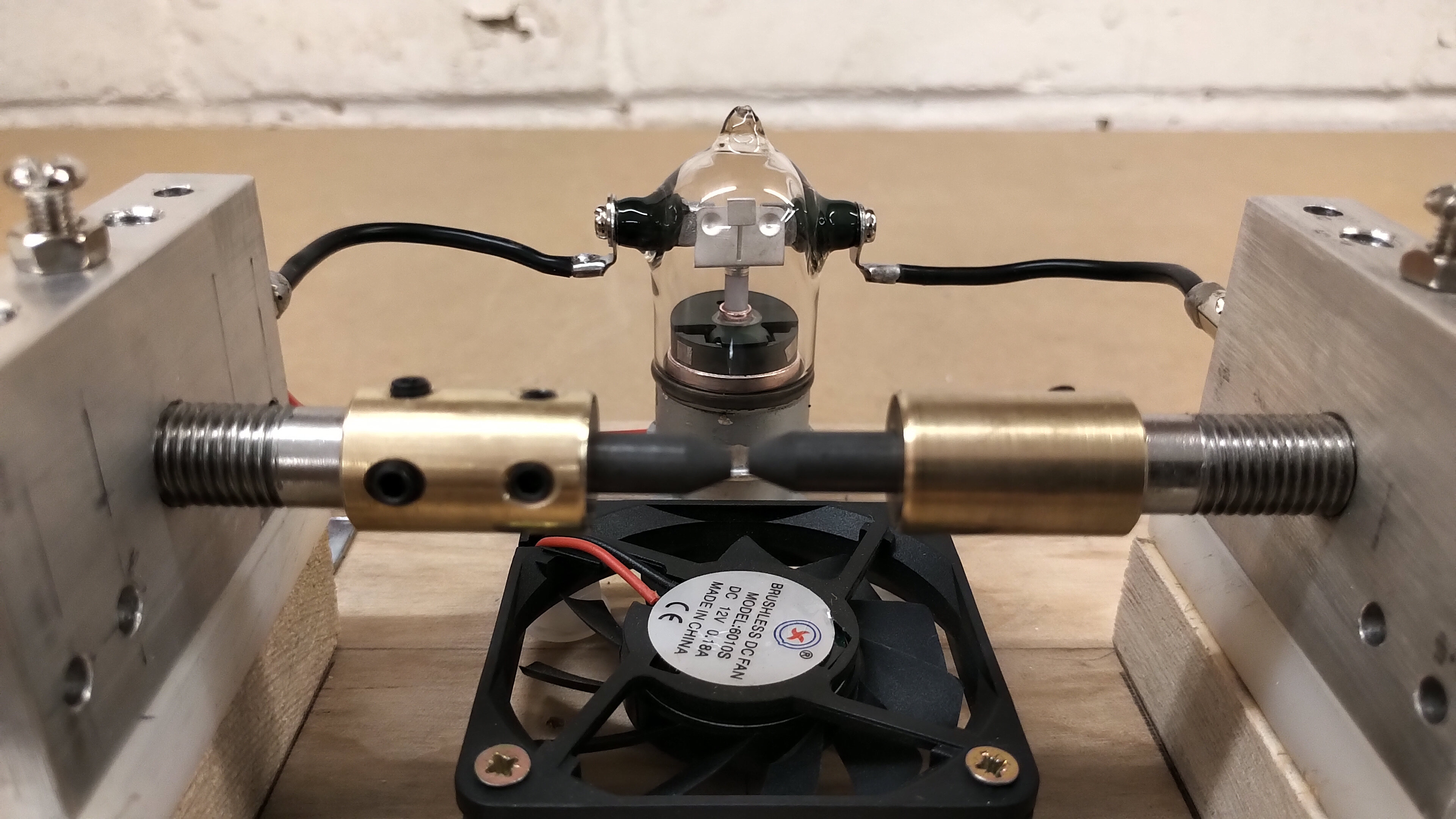
The video shows a range of different materials mounted in a pendulum-like arrangement, that when brought in to close proximity to the single wire lamp load emitter, experience an attractive and in the case of certain materials, an additional repulsive force. The attraction of a material can be almost instantaneous on application of the emitter power, or in some cases can take a period of “charging” time to reach a sufficient level to pull the material towards the surface of the emitter. In most material cases the sample is retained on the surface of the lamp for a period of “discharging” time before being released from the surface after the emitter power is turned off. The responses of the different materials to radiant energy and matter emanations from the lamp are as follows:

Aluminium – attracted towards the emitter over a distance of up to 20mm with an electrical power level at the lamp of ~40W, (power present at the emitter lamp is estimated based on its relative brightness when illuminated at 100% of its nominal rating of 25W). 10mm at ~20W was demonstrated on the video, and this material is readily retained on the emitter surface after power off. No repulsion events were observed with this material.

Copper – both attracted and repulsed from the surface of the lamp at a distance of ~8mm at ~20W. This material is more gently attracted to the emitter but is more unlikely to be retained on the surface. The most observed phenomenon is that the copper in coming into contact with the lamp glass is then repulsed quite strongly from the surface rather than being retained on the surface. The repulsion has a defined force rather than a simple falling-away or bouncing off of the glass surface. The attraction and repulsion at the correct distance from the emitter leads to a sustaining mechanical oscillation of the pendulum.

Acetate (cellulose) – not attracted towards the emitter even at distances <1mm at up to 50W of emitter power. However at much high powers >100W with a different lamp, very small movements have been possible in the region of ~1mm from the lamp surface. Slow to attract over the distance, and very quick to release, implying very low pull force, and very low charging effect.

Biomatter (fresh and dried) – in this case both a fresh and dried leaf sample were strongly attracted to the lamp  over a distance up to 20mm at ~20W. This material gives the most instantaneous response to emitter turn-on with very rapid movement to the lamp surface. This material is also barely retained on the lamp glass after emitter turn-off, being almost as quickly released as it is attracted to the surface. No repulsion events were observed with this material.

Cardboard – in this case the cardboard is very old originating from the original inner box of a Weston 425 meter, and showed good attraction up to 5-10mm  at ~20W. This material is not retained on the lamp glass after emitter turn-off, and no repulsion events were observed with this material.

Clearly from this experiment it can be seen the emanations from the lamp emitter result in a physical force exerted on the material. This physical force is attractive for all of the materials, including the acetate, but varies very widely in scale based on the material type. Surprisingly the biomatter exhibits the strongest attraction, followed by the metals, all the way down to the insulator with only very small attraction at much higher powers. Only the copper shows a sustained repulsive force but only after an attractive event has first pulled the material to the surface of the glass of the lamp, almost as though an inversion occurs at the surface contact and the material is then repelled away. There is no situation where a material has been repelled away from the lamp at turn-on without first being attracted to the surface.

By studying the nature of the experiment it does at first appear like a “charging” effect. Emanations or wavefronts emitted from the lamp emitter cause negative charge accumulation at the surface of the material, where the degree of surface charging depends on the material type, its “impedance” to the emanations, and the material conductance. If this where the case it would be similar to an electrostatic force where two or more materials are attracted or repelled by the difference in their surface state charge.

It has been suggested[3] that the attractive force is magnetic in nature stemming from eddy currents generated in the material by the incident emanations. I have not so far been able to demonstrate this since the introduction of a strong bar magnet into the experiment makes no difference either attractive or repulsive to the material under test. The material still behaves as indicated above, and at the same power levels and distances, irrespective of the magnets influence on the experiment. However, this is not to say that the magnetic field of induction Φ is not involved in this process. This can also be partly supported by the observed sustained current through a neon lamp load in the capacitor charging part of the experiment, which could suggest that both Ψ and Φ are present within the nature of the radiant energy emanation.

At an empirical level this would appear to make sense, if the radiant energy is an emanation resulting from a displacement event at the emitter, and the displacement event involves the undifferentiated Ψ and Φ acting in temporal and spatial coherence, it would correspond that the emanation from this event is in phase, longitudinal in nature, and forms a forward moving unidirectional wavefront of “electrical pressure”. In this way this emanation conveying both Ψ and Φ when incident on materials within the transmission medium could stimulate an electric, magnetic, or a combination response from the material. This stimulated response may involve energy accumulation and storage, and also dissipation of energy through exertion a physical force, electromagnetic emission or absorption (light and dark), thermodynamic changes (temperature or pressure changes), or even perceptual changes of the surrounding medium.

As a coherent pressure wave its transmission over distance may be very large, transferring energy from the pressure wave to incident materials in the surrounding medium, or even becoming self-sustaining with distance through amplification from suitably arranged material forms and apparatus. The velocity of the pressure wave needs to be considered and suitable apparatus for its measurement arranged, however in the coherent state as an emanation from a displacement event it is considered possible that energy is displaced between source and load at velocities exceeding c the transverse electromagnetic speed of light in the vacuum.

In summary, radiant energy like emanations very similar to Tesla’s original observation in his patent, can be observed from a suitable load, (impedance change), placed in the cavity of a single wire transmission medium. These emanations are conjectured to be the product of coherent underlying processes which stimulate a range of different responses from incident materials. The emanations are conjectured and discussed to be directly the product of displacement events generated by longitudinal electrical pressure imbalance at the single wire load.

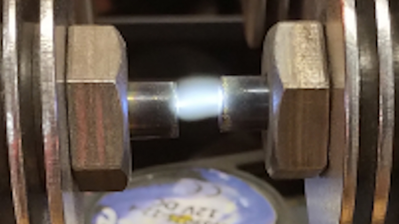
Low temperature light emission and “cold” electricity

In Lindemann[4] the term “cold electricity” was used to describe experiments and observations by Gray (via Valentine)[5], based on light emitted by incandescent lamp loads, which was not accompanied by the normal rise in temperature expected from this type of resistive load, but rather the lamp had a cool glass surface when emitting “full power” illumination. Gray further demonstrated this by illuminating to full power an incandescent lamp submerged in cold water, which would ordinarily lead to fracture of the lamp glass. In the case of illumination by “cold electricity” no such fracture damaged was observed over sustained illumination periods.

In my experiment with incandescent lamps in the single wire load it was observed that the temperature of the lamp was quite low, and could comfortably be touched or held by the human hand after sustained illumination, equivalent to illumination at a full input power of 25W. This was compared to a control lamp, (same 25W pygmy make and style), powered from the normal line supply. After the same period of illumination where both lamps appeared the same brightness, the lamp in the single wire could be easily touched and held, whereas the control lamp was too hot to touch without causing a burn to the skin.

It appears likely from this experiment that the light being observed in the single wire lamp is, at least in part, emitted by a different process than the control lamp. Continuing the consideration from the previous section, and looking at the response of different materials to radiant energy emanations, it is possible to imagine that the filament of the bulb as a material that radiant energy is impinging upon, has its own unique and specific response to the coherent pressure wave emanation. In this case the response of the material to the radiant energy is to emit electromagnetic radiation in the form of light, which was not entirely generated by the resistive heating of the filament from the electrical current flowing in the single wire.

In a normal transverse and closed electric circuit case an incandescent lamp will generate light as emission from a resistive heated filament, where the colour temperature of the light is based on the filament material and temperature. Heat from radiation and conduction through the gas in the lamp heats the outer lamp glass to a temperature more than sufficient to cause sustained burns to biomatter. In the single wire lamp load light appears to be emitted through the filament response to the coherent longitudinal wavefront, which does not result entirely from resistive heating of the filament. Since the lamp does warm a little there is most likely a combination of processes going on, so some light emanation from radiant energy coherent processes, and some transverse current resistive heating in the filament.

This implies that there is a combination of the longitudinal and transverse electrical transmission modes within the single wire. It follows that improvement of the experimental system and boundary conditions could lead to a reduced transverse component, and a more pure longitudinal pressure wave in the single wire cavity reducing the heat emitted from the load to a level comparable to that observed by Gray in his experiments. In this case we would expect the temperature of the single wire lamp load to reduce from slightly warm to very cool, or even to cold in optimal experimental conditions and apparatus. Optimal conditions here means firstly reducing the transverse components within the single wire, which implies establishing the stable balance of Ψ and Φ boundary conditions in the complete system across the generator, primary, secondary, and cavity. And secondly it requires an increase to the uni-directional impulse like nature of the stimulus, where the increased non-linear inter-action between Ψ and Φ results in more displacement events and hence stronger emanations from the emitter.

In summary, it is considered that radiant energy emanations on the filament result in emission of light which is in part not as a result of resistive heating of the filament, which shows a similar result to that reported by Gray and considered by Lindemann. Improvements to the experimental apparatus and operating conditions should result in an increase in this phenomena, and will also help to confirm the validity of the conjectures made regarding displacement and radiant energy. It should be noted here that whilst I understand the label of “cold electricity” given to this phenomena, I find that the process conjectured here as being responsible for this phenomena is definitely not a “cold” principle. “Cold” in these terms implies the absence of something or something separated, in this case the energy to elevate the temperature through transverse dissipation, whereas I consider the emission of radiant energy, and the filament material response to that emission, to be an inclusive process which involves the coherent inter-action of both Ψ and Φ.  Thus phenomena and emanations resulting from displacement are inclusive in nature, involve all parts of the system and medium in dynamic balance, and imply a sense of warmth, wholeness, and completeness.

Radiant energy accumulation and charge storage

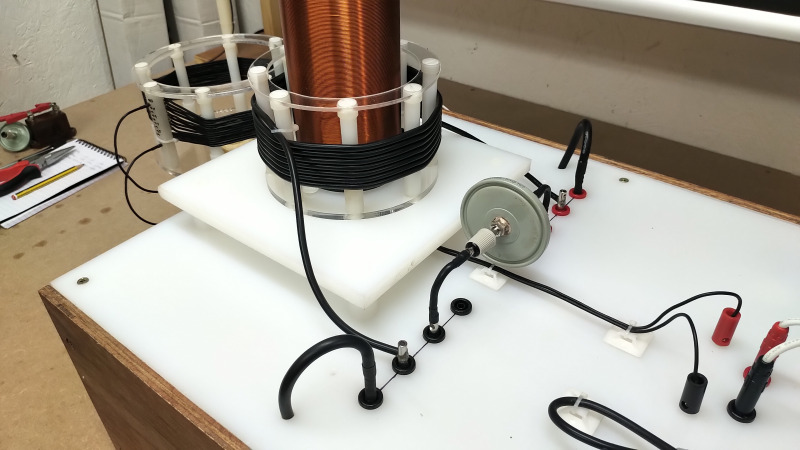
In this experiment a capacitor is electrically charged by radiant energy emanations, showing energy transferred from the single wire emitter, accumulated in the capacitor, and then discharged through a neon bulb in the form of a spark discharge. In many ways this a similar consideration to the section on attractive and repulsive force, only additional accumulation can occur due to the capacity and storage of energy on the capacitor, which persists for much longer time intervals after the radiant energy emitter has been turned off.

An interesting observation to note from this experiment is that during the “charging” of the capacitor a smaller single wire circuit, or tributary from the main cavity, is created in the form of the capacitor in close proximity to but not touching the lamp, a wire connected to the other terminal of the capacitor, and a neon lamp load connected to the end of this wire. The active region of the neon lamp appears in the cavity tributary where there is also a short lead out of the neon lamp acting as the short fly-lead at the end of the single wire cavity, and ensuring there is a small but non-zero single wire current in neon load. During the charging stage the neon bulb lights continuously showing a single current flow down the tributary, and the transient like nature of the accumulating tension on the capacitor.

When the capacitor is adequately charged the main single wire load emitter can be turned off, and the charged capacitor and tributary circuit removed from the vicinity of the main experiment. The charge of the capacitor is retained over considerable time without any part of the circuit being closed with the neon bulb. When the circuit is closed the stored energy discharges rapidly through the neon bulb, with a characteristic snapping sound, and a bright bluish white discharge light in the neon bulb. The nature of this spark discharge shows that there is considerable tension on the capacitor, in fact it can be measured using a high voltage probe to be up to ~10kV, and considerably more than the maximum rating of the capacitor, (in this case 4kV). Unusually the capacitor appears unaffected by application of this overall tension across its terminals, and can provide a rapid and high-current discharge through the neon bulb.

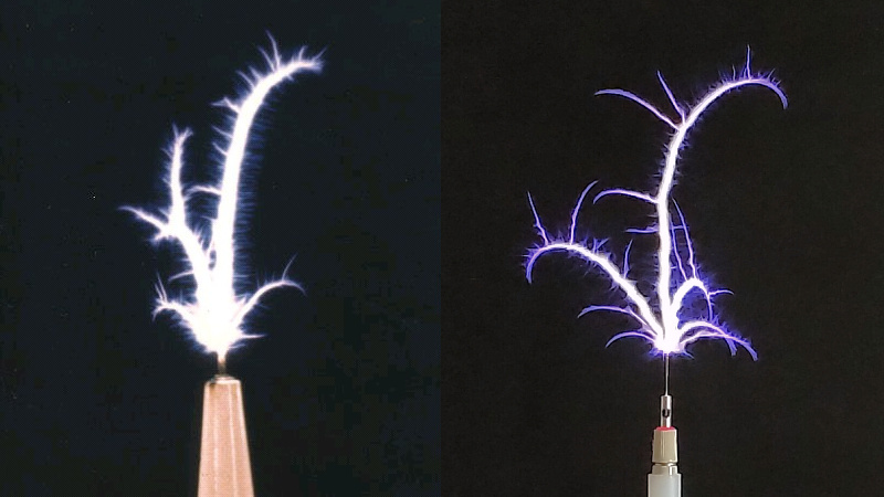
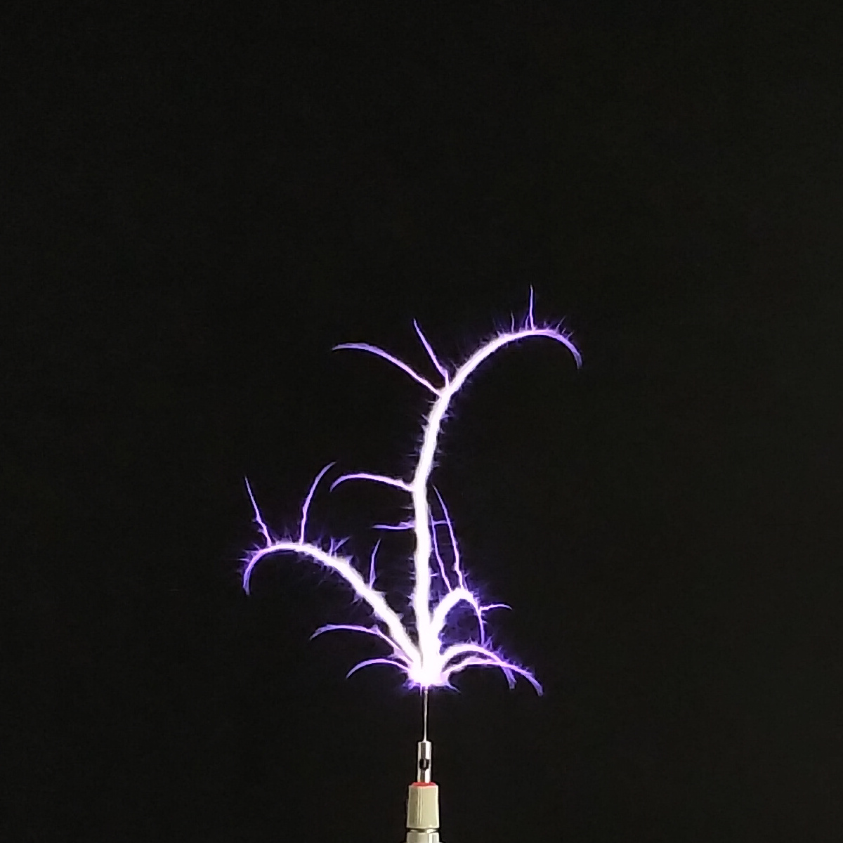
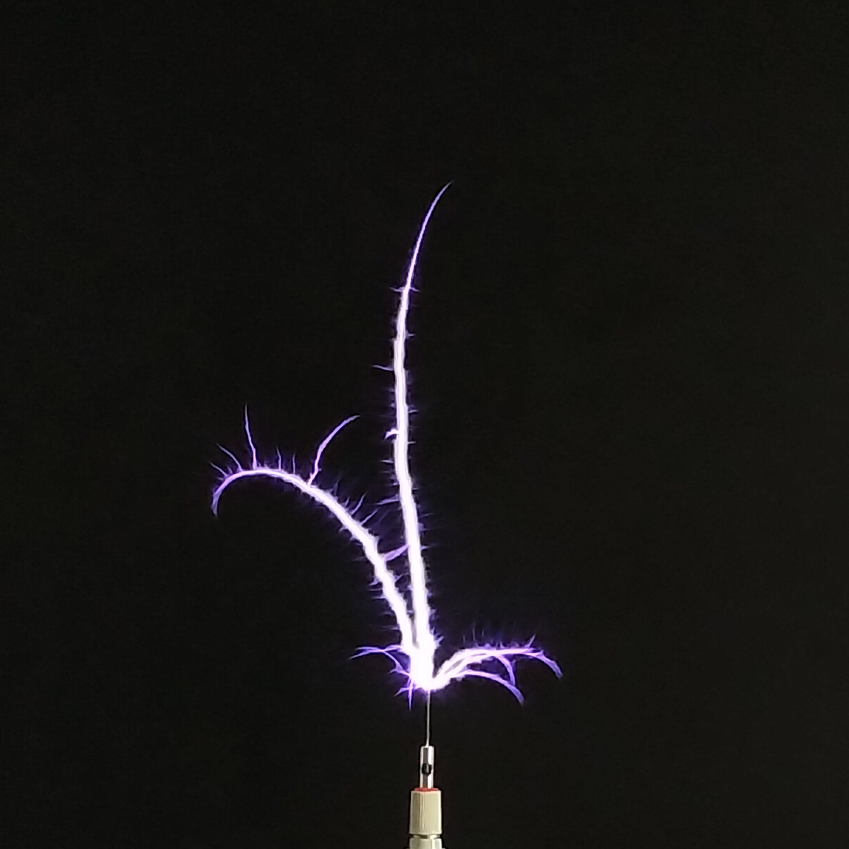
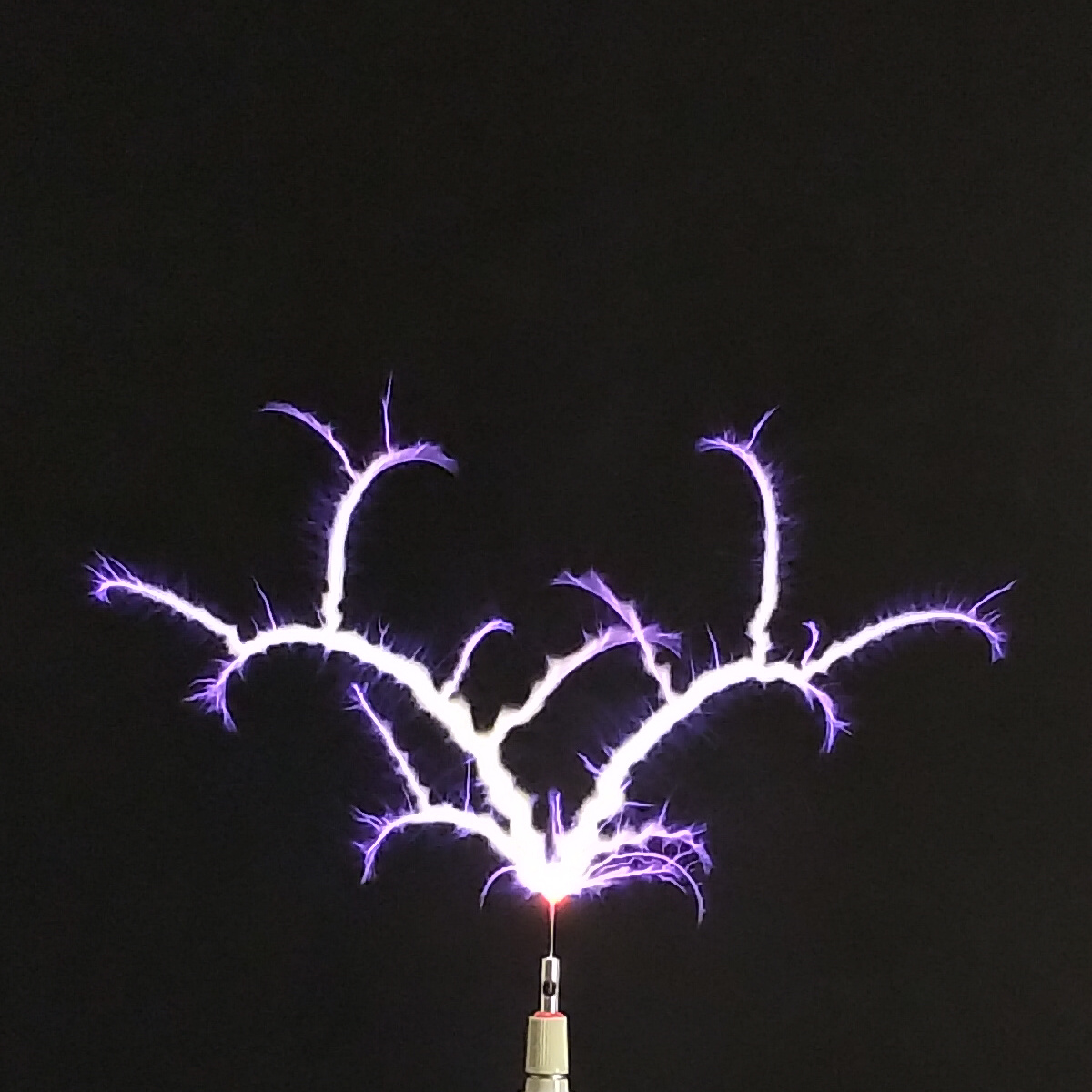
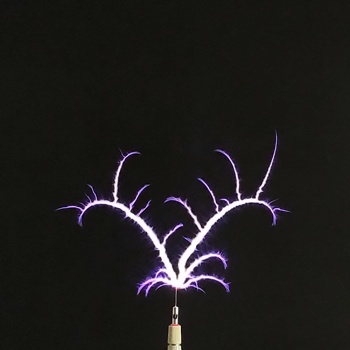
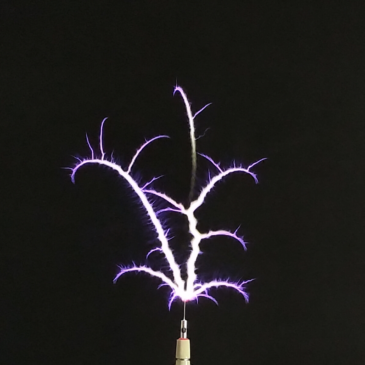
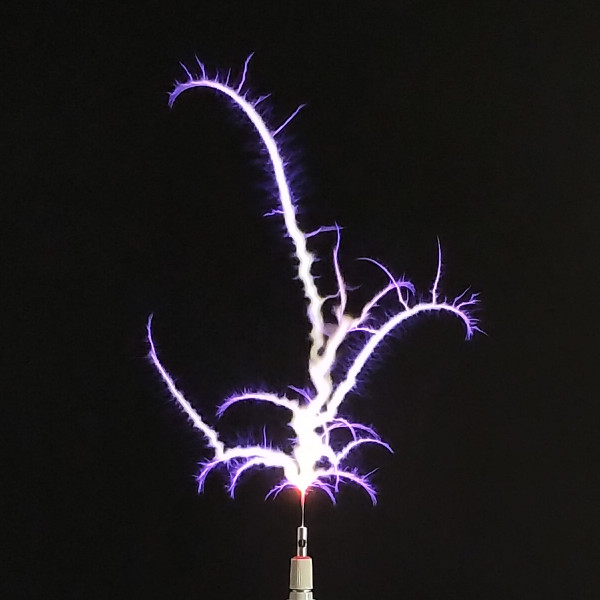
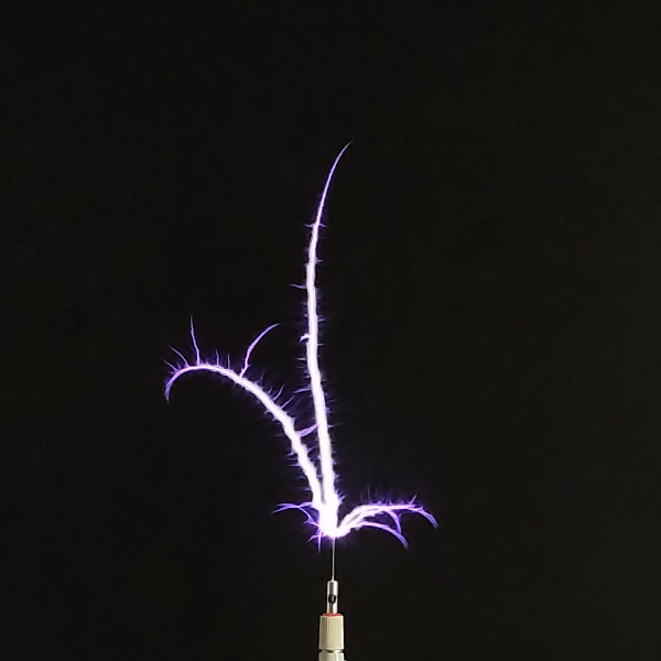
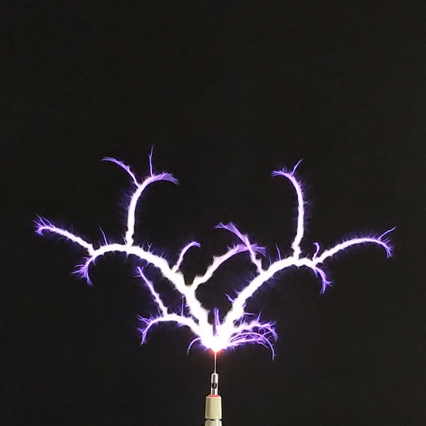
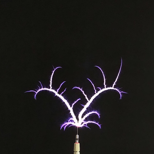
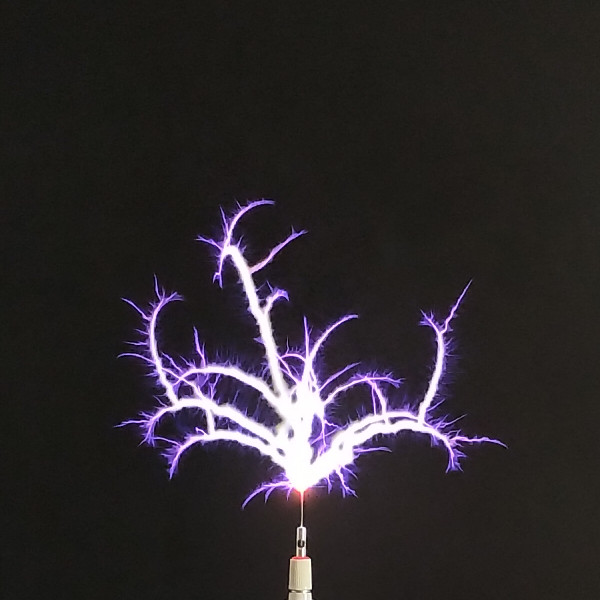
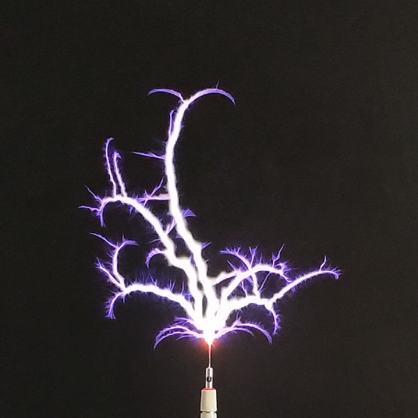
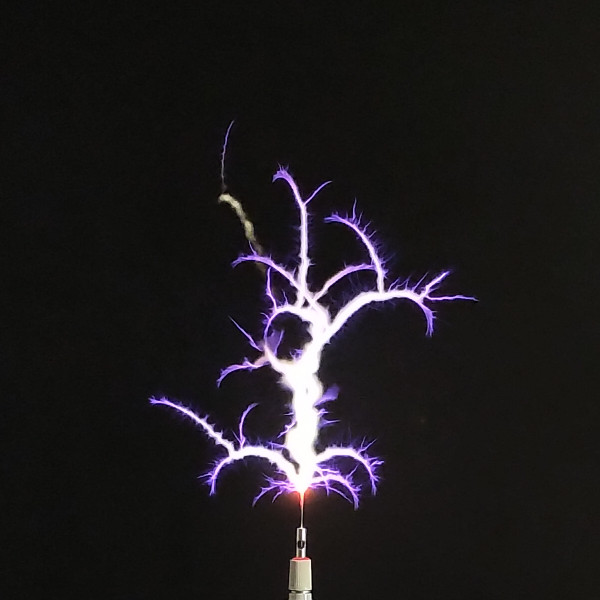
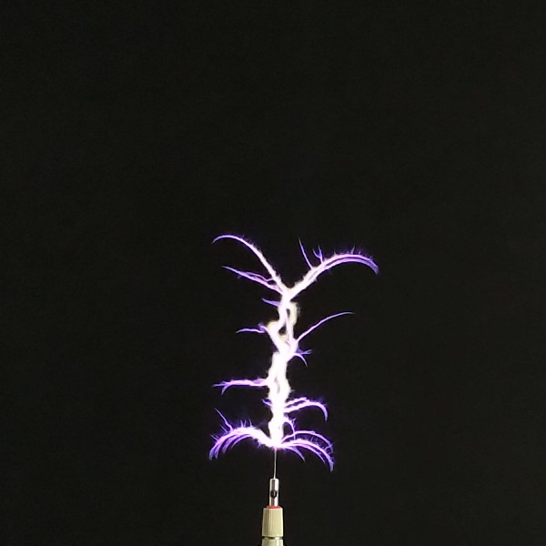
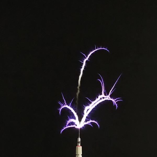
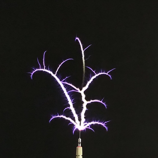
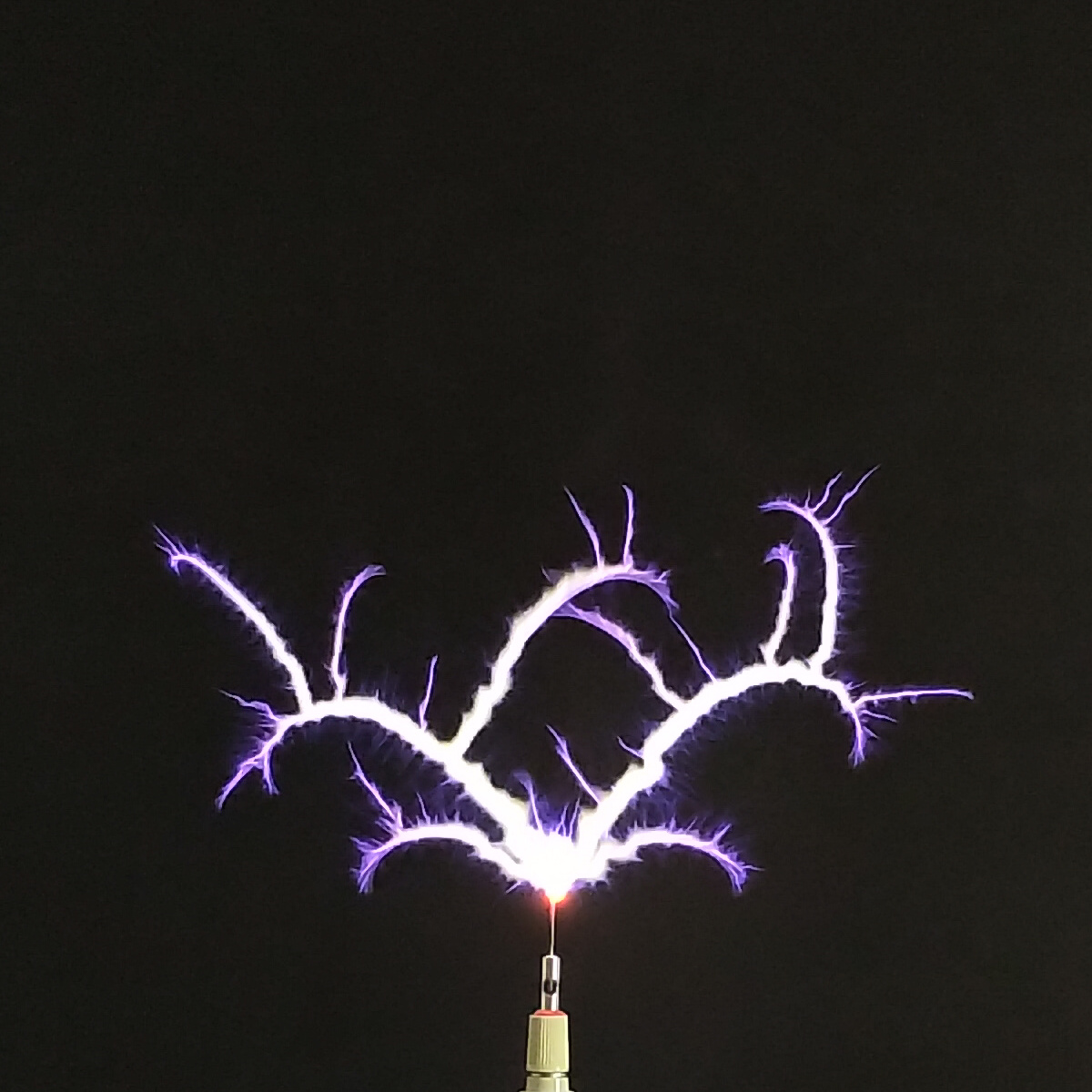
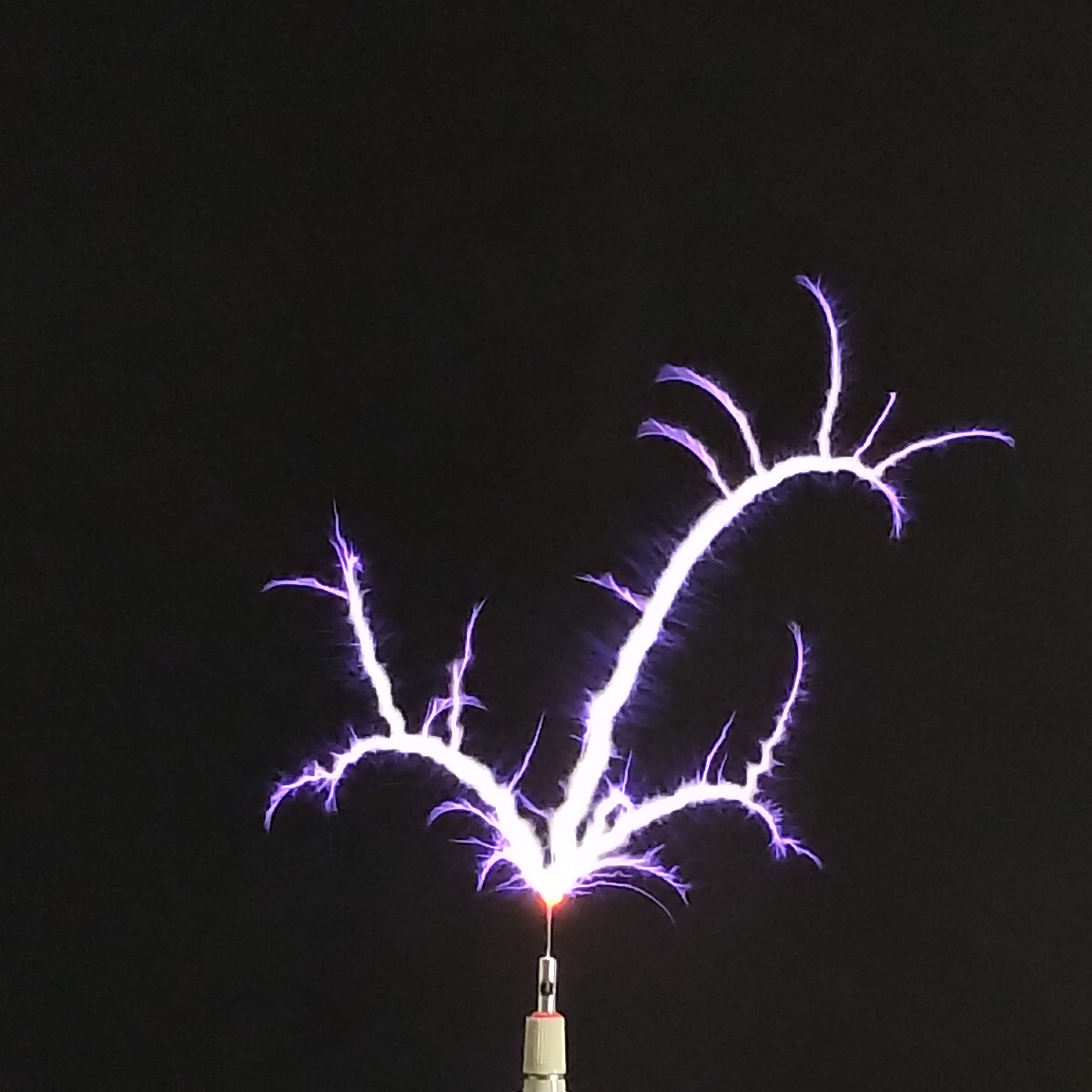
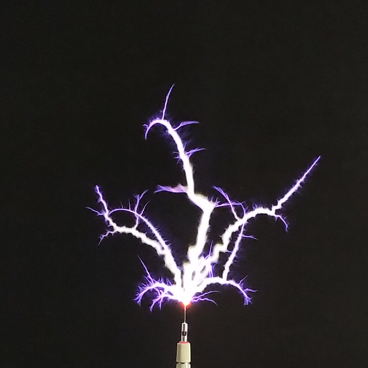
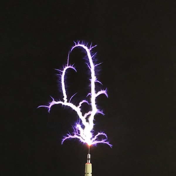
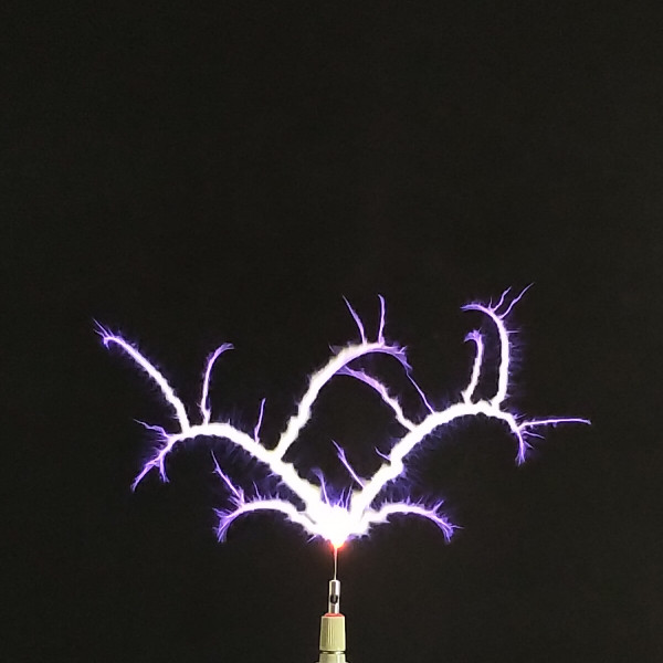
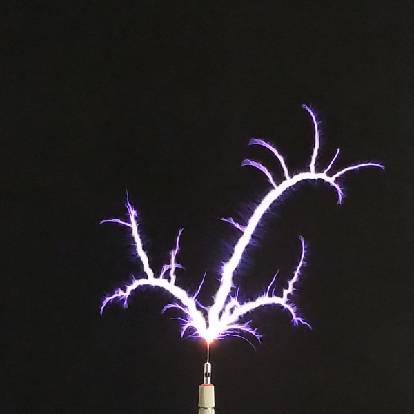
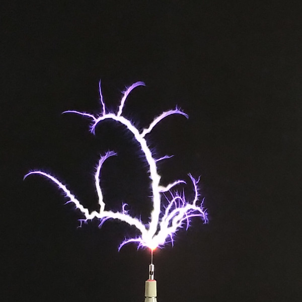
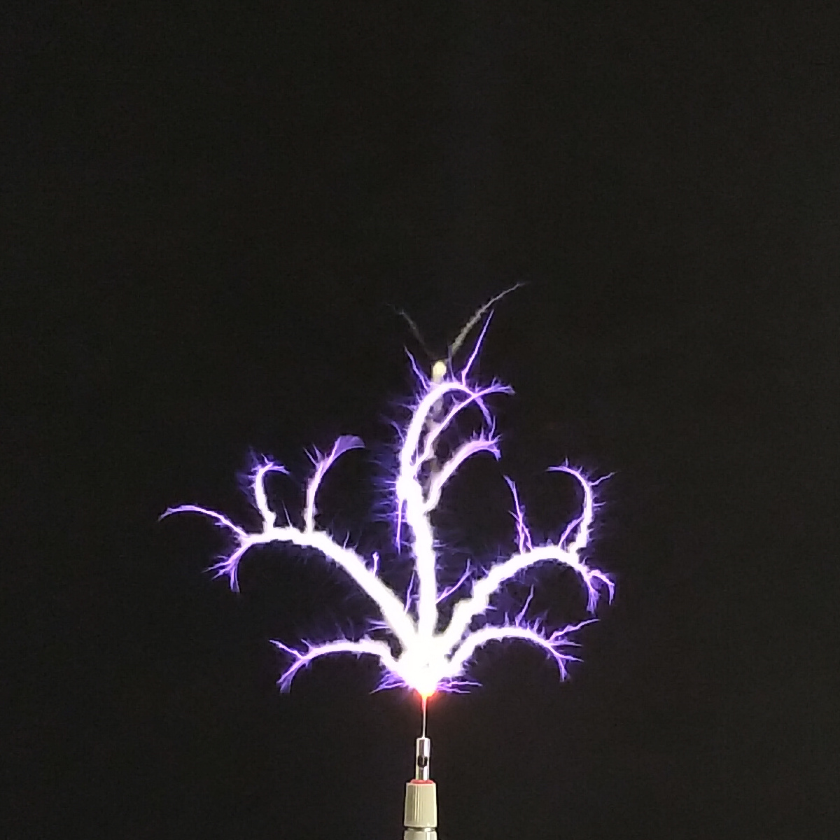
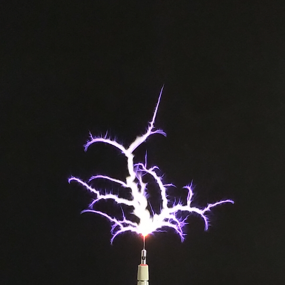
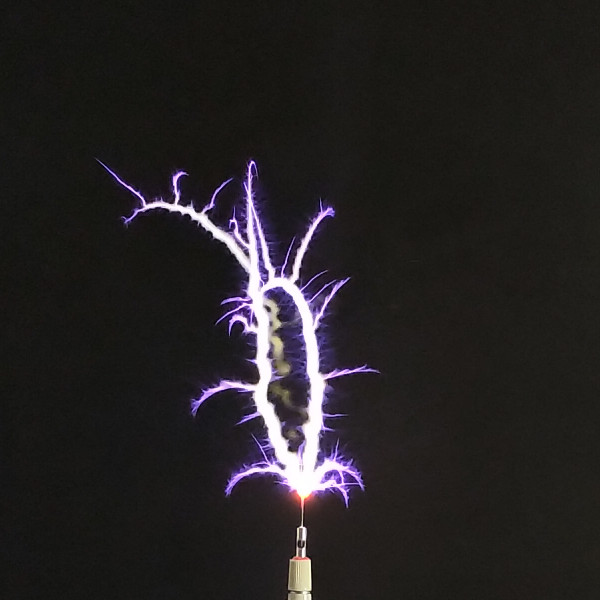
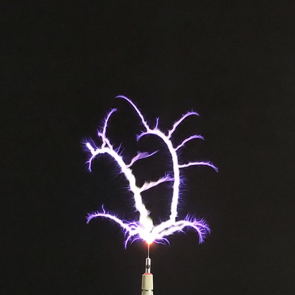
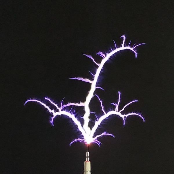
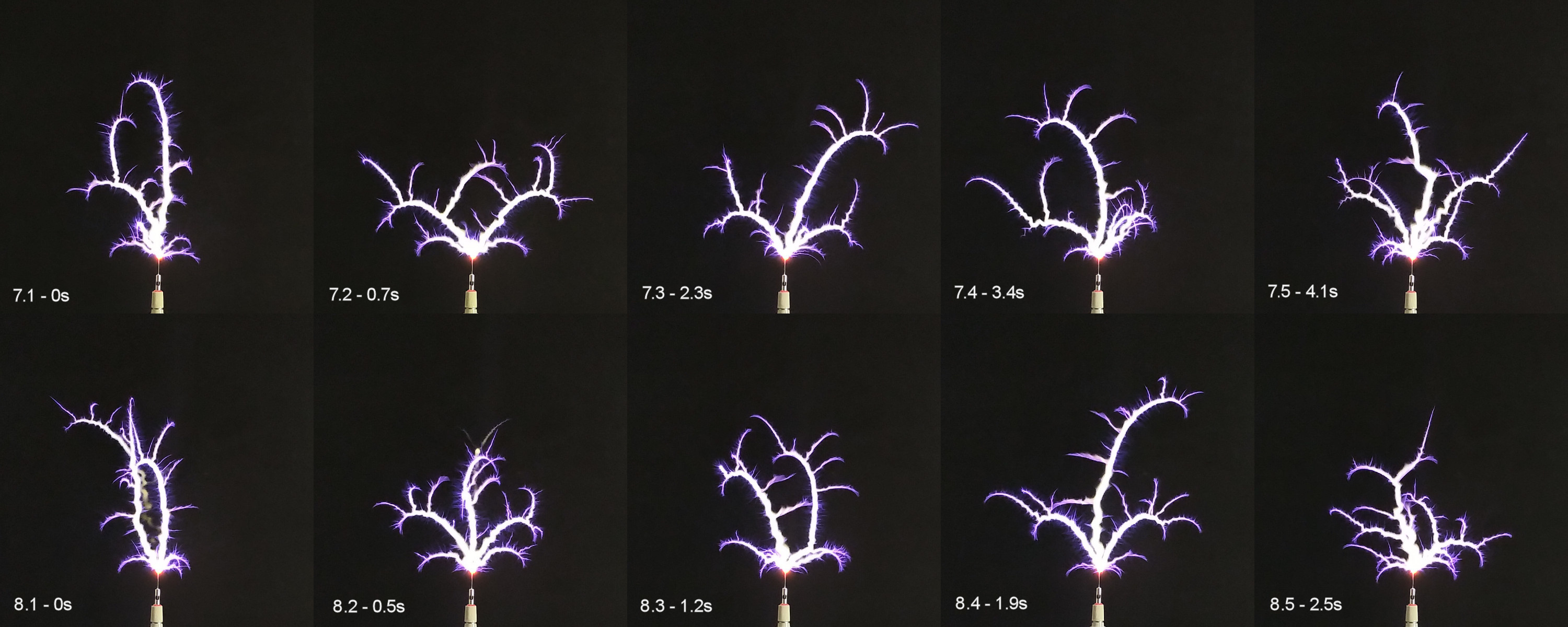
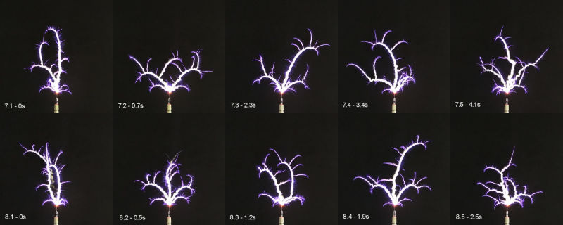
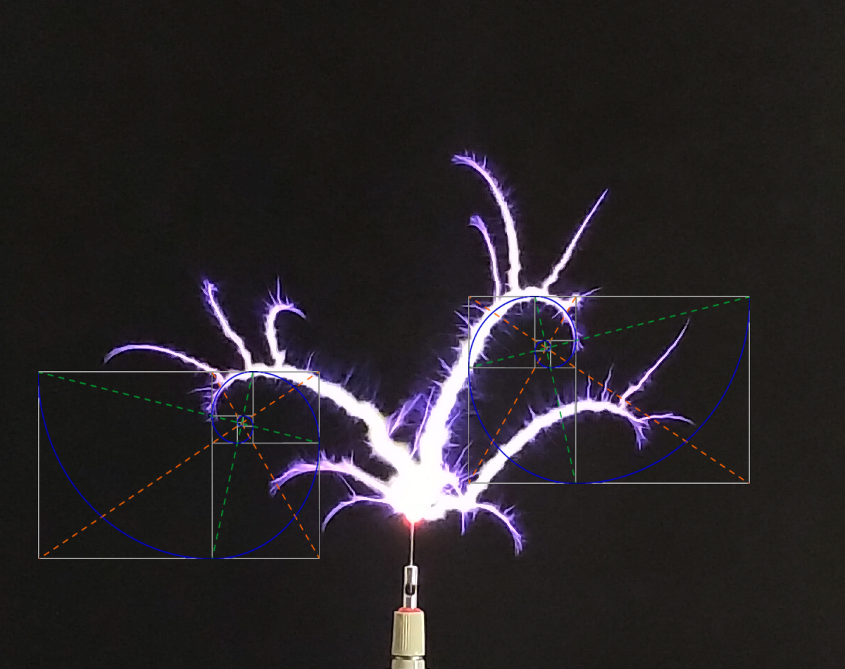
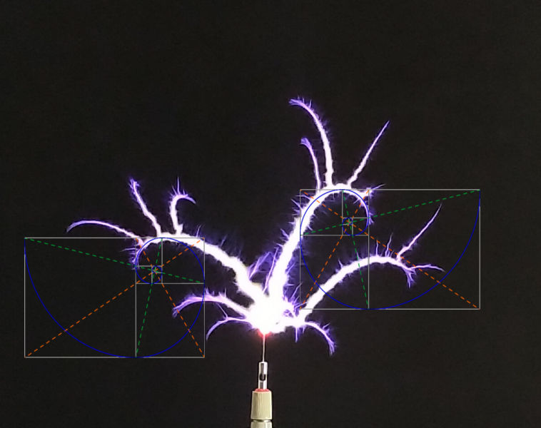
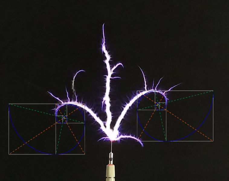
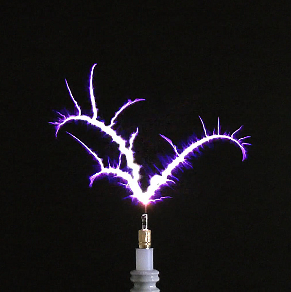
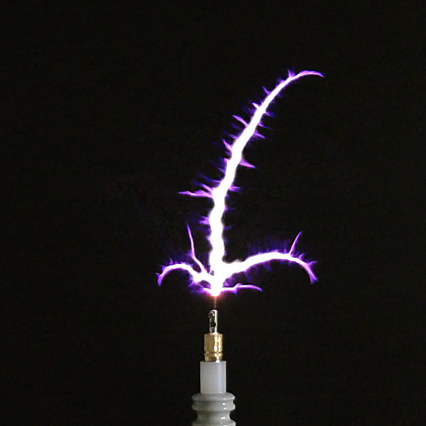
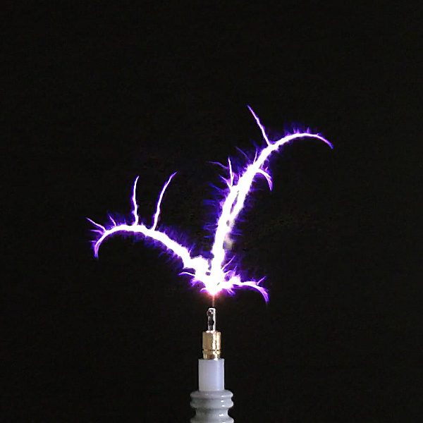
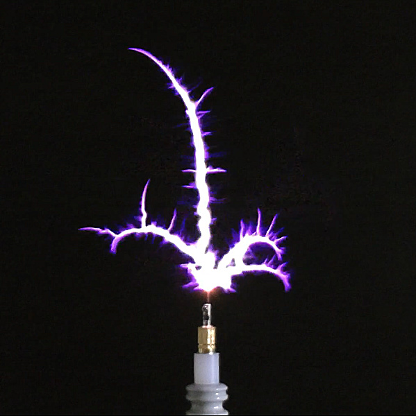
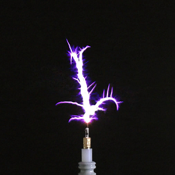
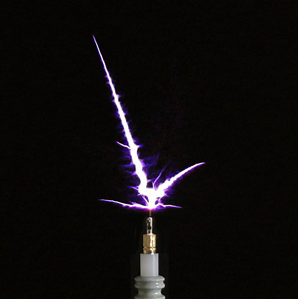
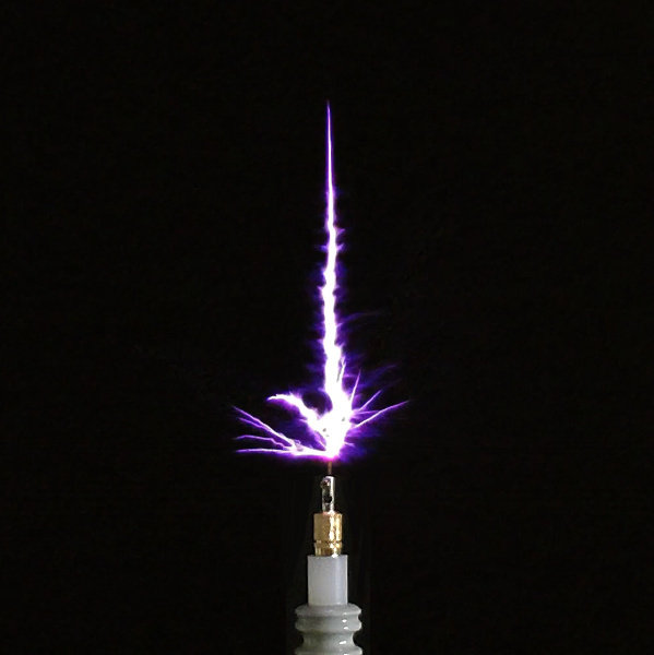
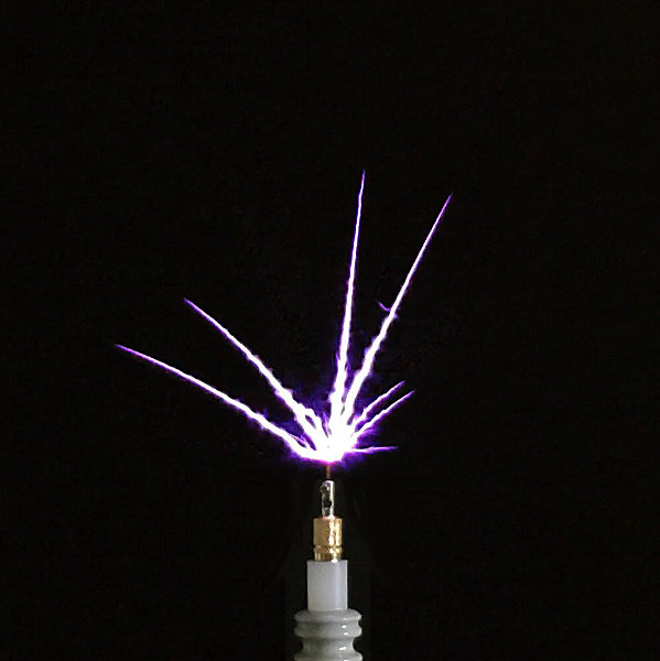
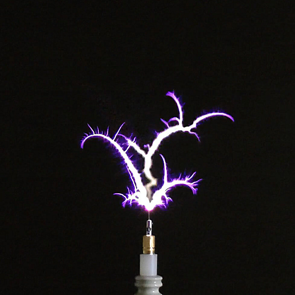
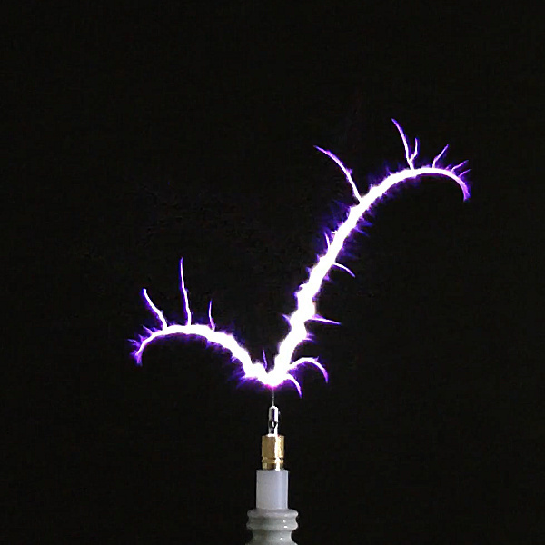
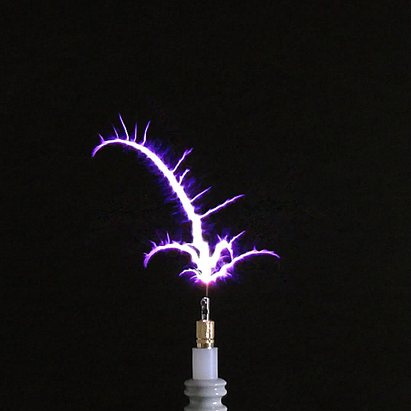
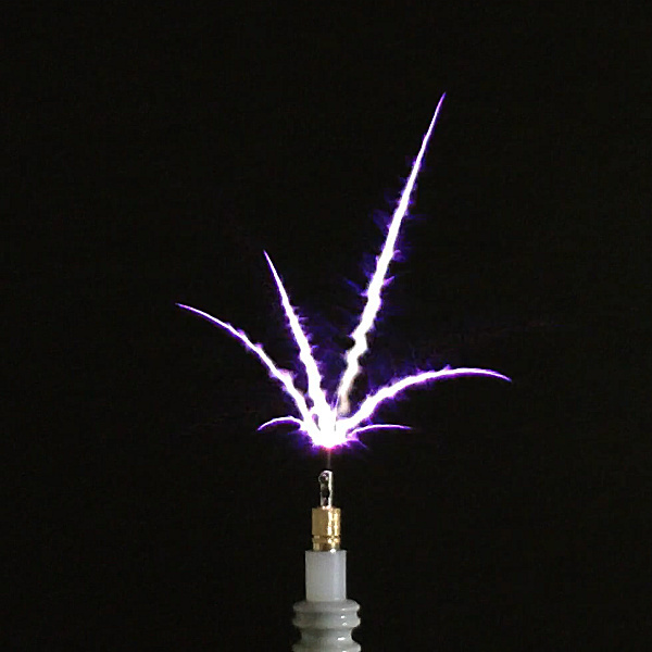
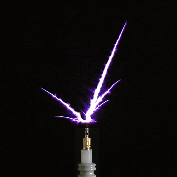
In summary, energy can be stored in a tributary single wire circuit incorporating a capacitor as an accumulator, when a radiant energy pressure wave is incident on one terminal of the capacitor. The experimental arrangement used with the load attached by single wire to the other terminal of the capacitor, and kept open-circuit during charging demonstrates the possibility of the formation of single wire tributary cavities, which extend off the main cavity. In some ways this is similar in analogy to the “fern” discharge effect demonstrated by Dollard[6], when exploring extra-coil discharge phenomena with a pair of cylindrical phase-locked TMTs.

Radiant matter pressure on biomatter and reaction forces

In this experiment I placed my fingers close to and around the single wire lamp emitter but not touching, and not close enough for a high tension discharge to occur between the filament and my fingers. It was clear to experience a vibrating pressure exerted on my fingers in similar accordance to Tesla’s observation that “… sources of such radiant energy throw off with great velocity minute particles of matter …”, Tesla[1]. This radiant matter appeared to exert pressure on my fingers, or at least the experience of pressure waves as if being struck by waves of minute particles.

In addition to this I observed, and can be seen on the video, a reactionary force exerted on the filaments of the lamp emitter so that they would move permanently into another position, or else oscillated around a median position until filament breakage or becoming stuck to the inside surface of the lamp glass. Either way the movement of my fingers around the glass of the lamp resulted in both the experience of an exerted physical force on them, and simultaneously a reactionary force exerted on the filaments.

Although Tesla was clear about the nature of these “great velocity minute particles of matter”, I am not convinced of this explanation in this experiment, but rather that the experience is similar to that observed in the section on attractive and repulsive forces, where both Ψ and Φ are coherently inter-acting to form an emanation where again the stimulated response may involve energy accumulation and storage, and also dissipation of energy through exertion of a physical force, electromagnetic emission or absorption (light and dark), thermodynamic changes (temperature or pressure changes), or even perceptual changes of the surrounding medium.

Longitudinal and transverse mode coupling, or transformation, in a single wire cavity

This is a complex topic but one that needs to be initially considered here if we are to move toward a proper understanding as to the principles of transmission that take place in a single wire conductor, its relationship to the transverse and longitudinal mode, and ultimately the underlying stimuli and inner workings of electricity, displacement, and radiant energy.

In experiments and discussions thus far the Tesla coil or TMT system has been considered to form a cavity in the secondary circuit, where single wire transmission medium phenomena can be easily observed and measured. It has been suggested by others[2,3] and conjectured by myself that the single wire open-circuit nature of these phenomena, is a result of the longitudinal mode of transmission in the cavity created within the TMT system, where both Ψ and Φ are coherently locked in phase, creating an electrical pressure wavefront that traverses the cavity between boundaries, being reinforced by successive oscillations from the primary, and either transferring the power to a distant load in the primary of a receiver, or dissipating the energy in the wavefront within a load of different impedance within the single wire cavity.

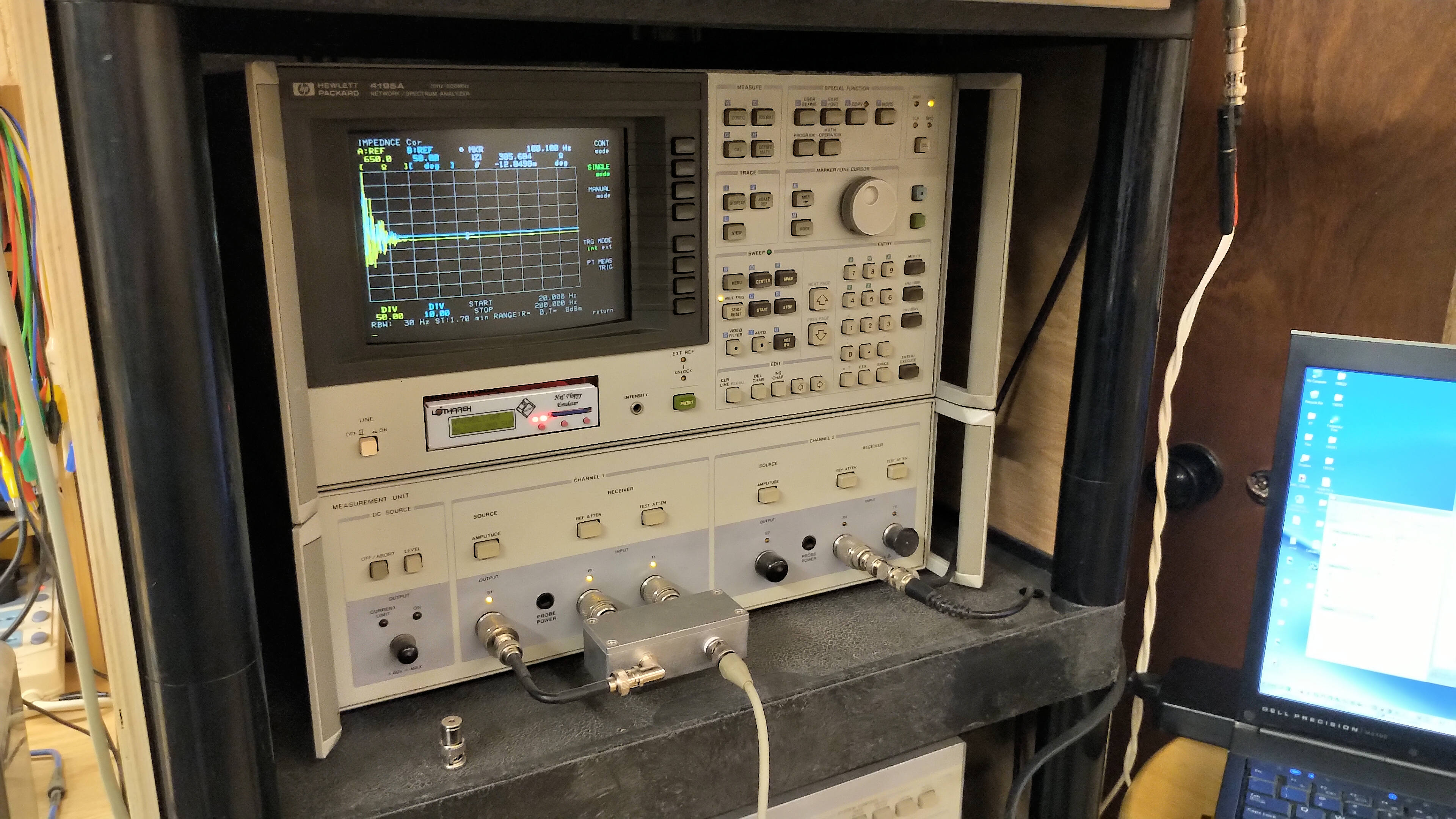
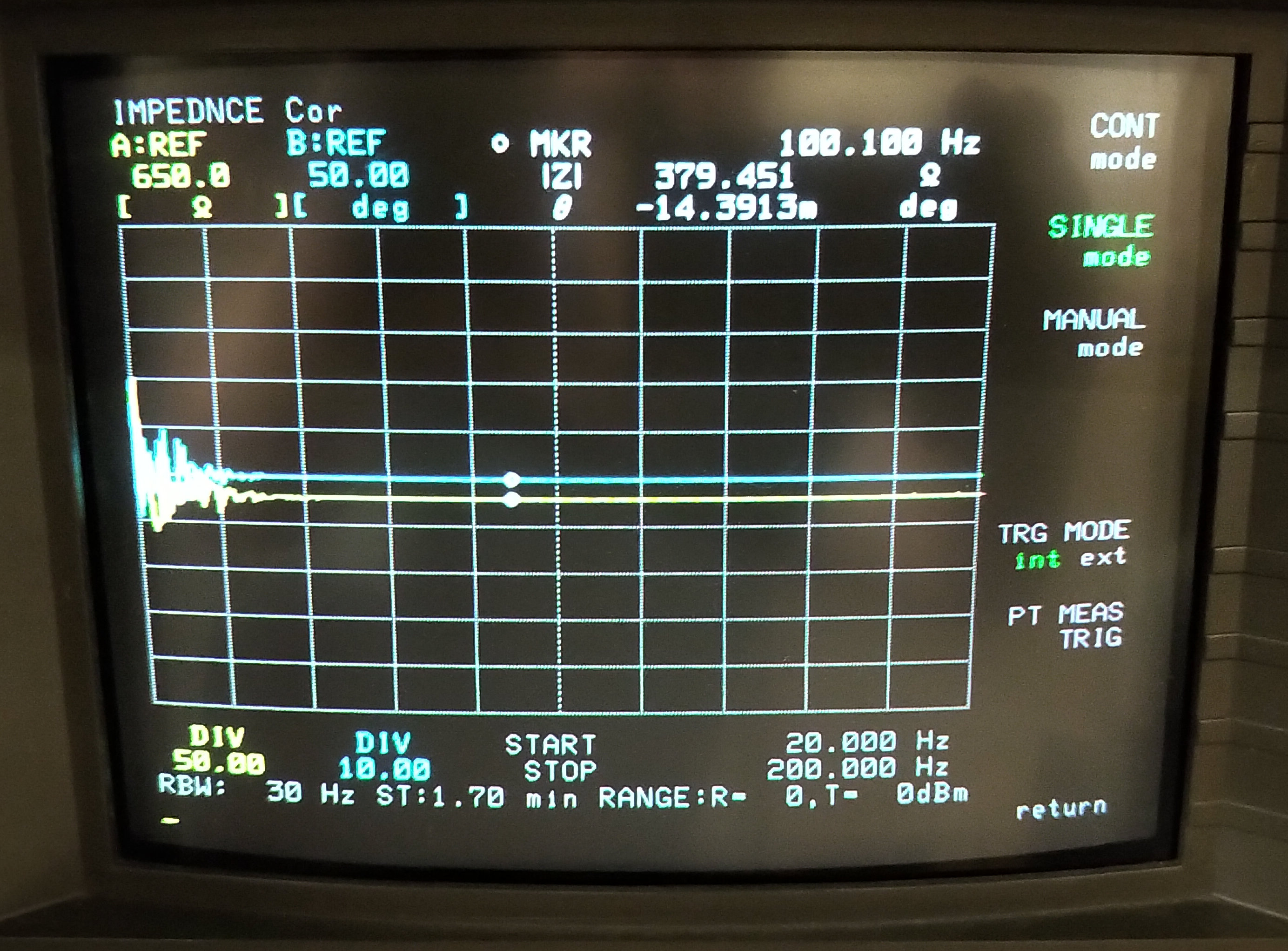
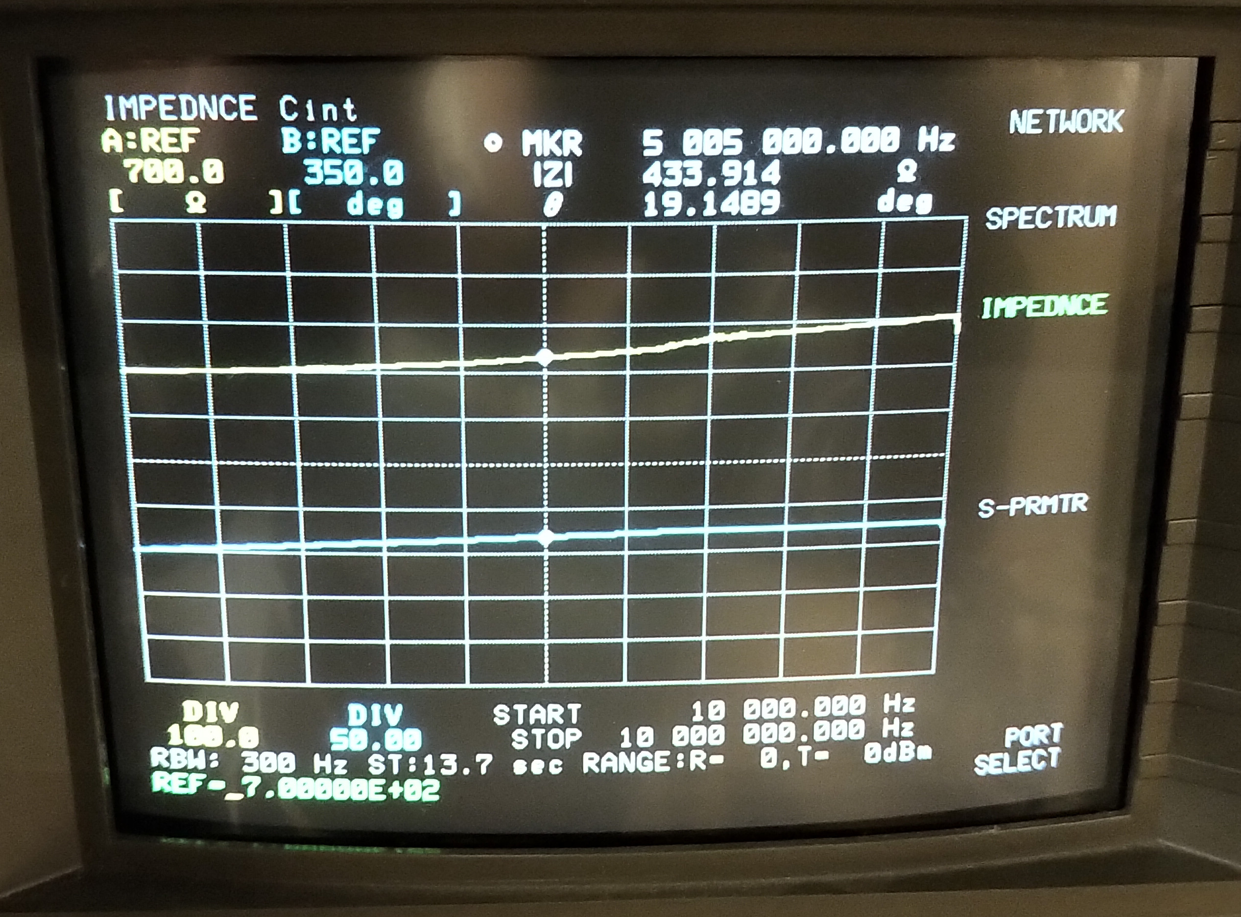
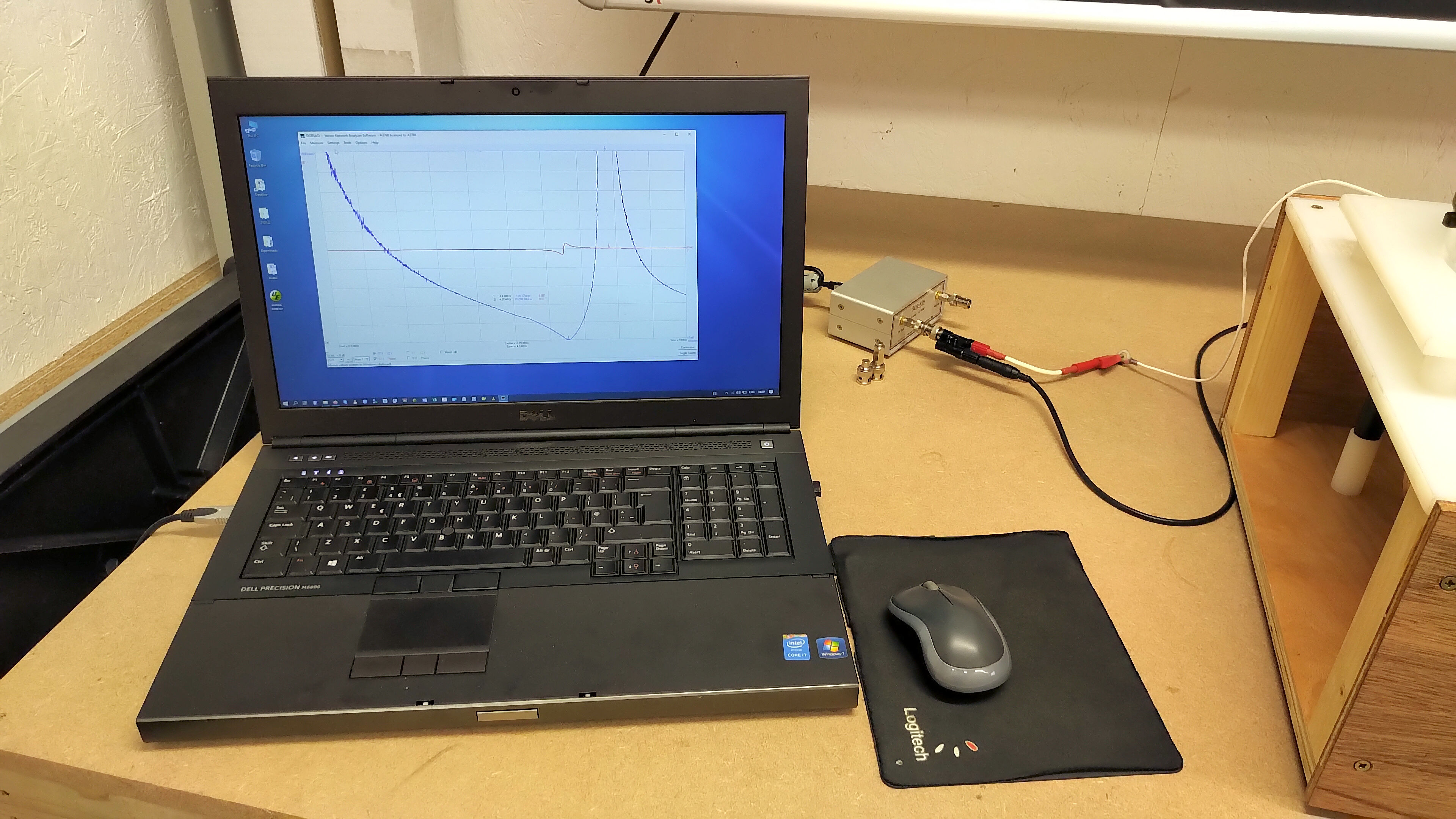
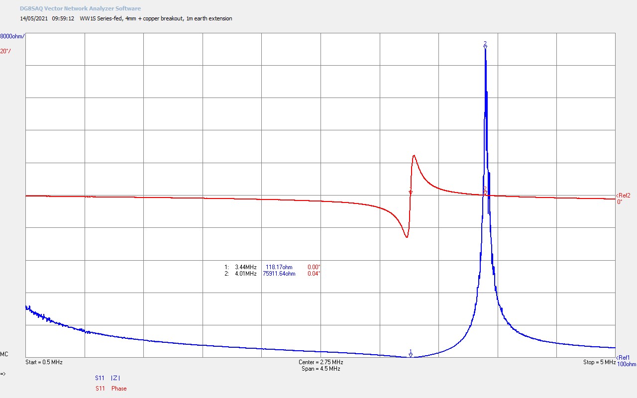
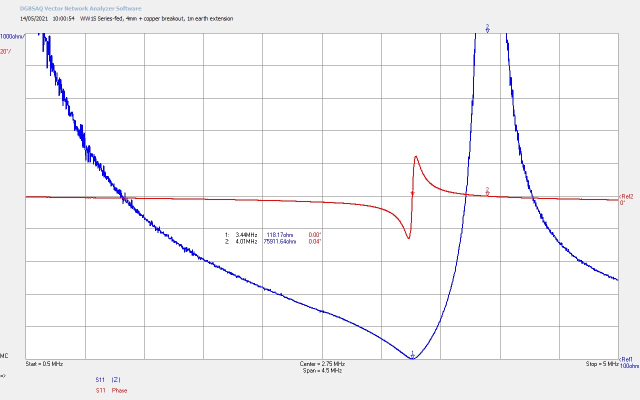
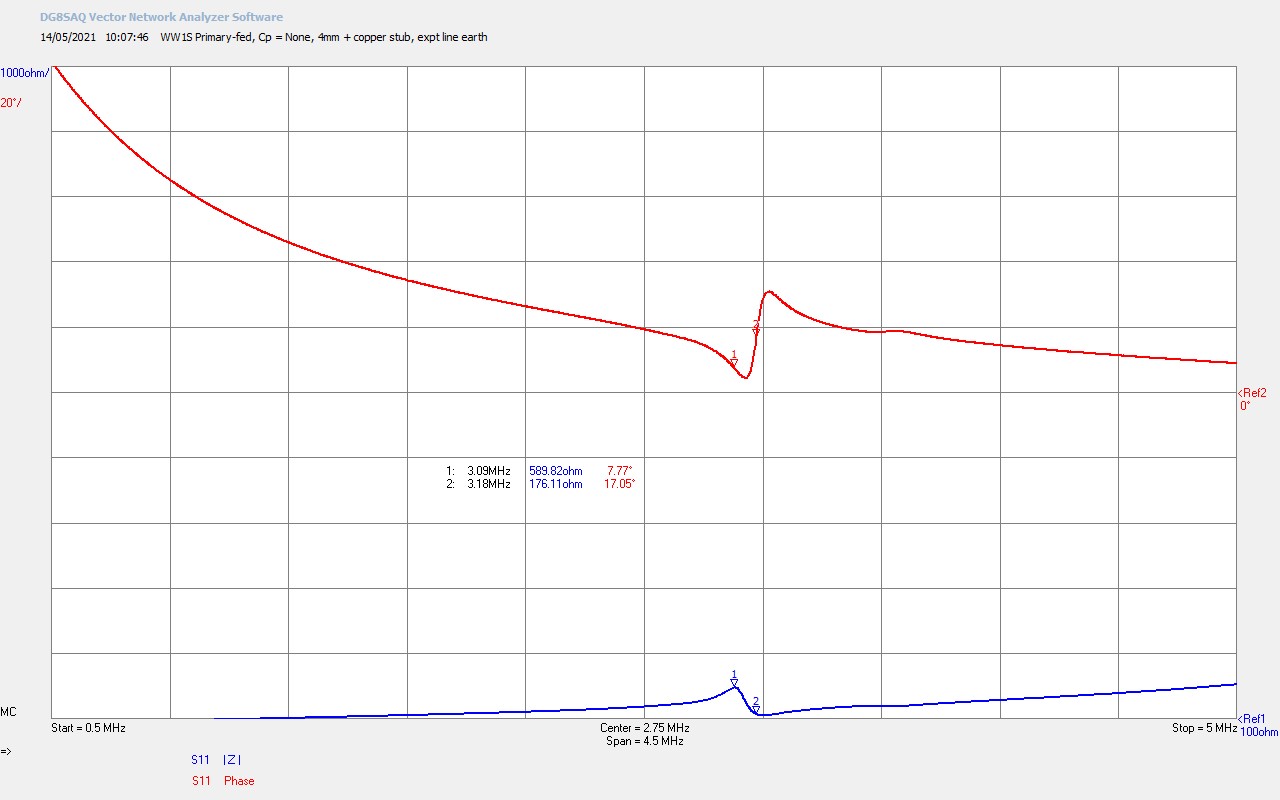
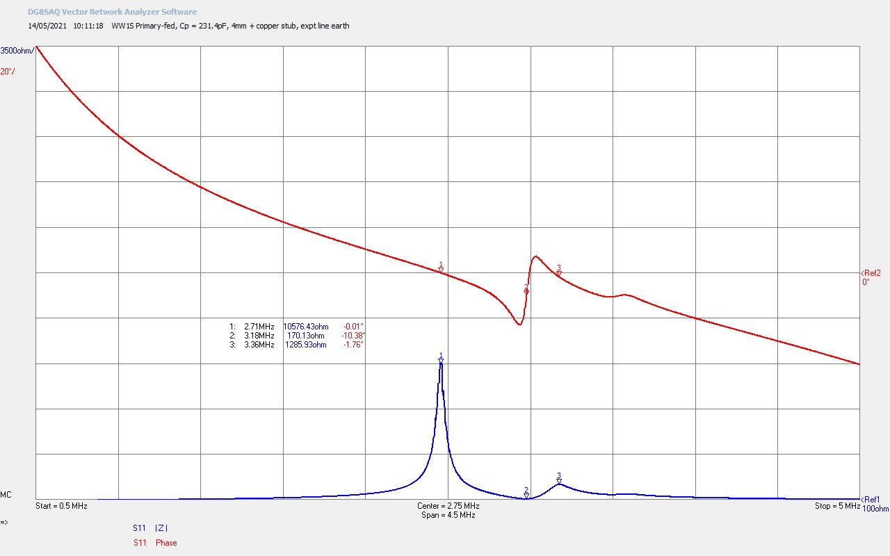
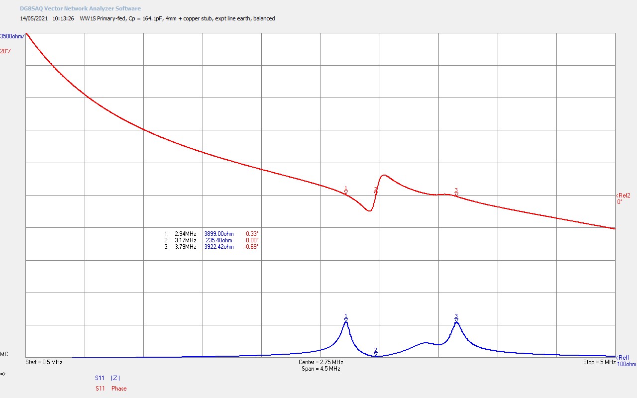
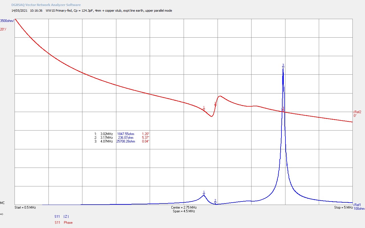
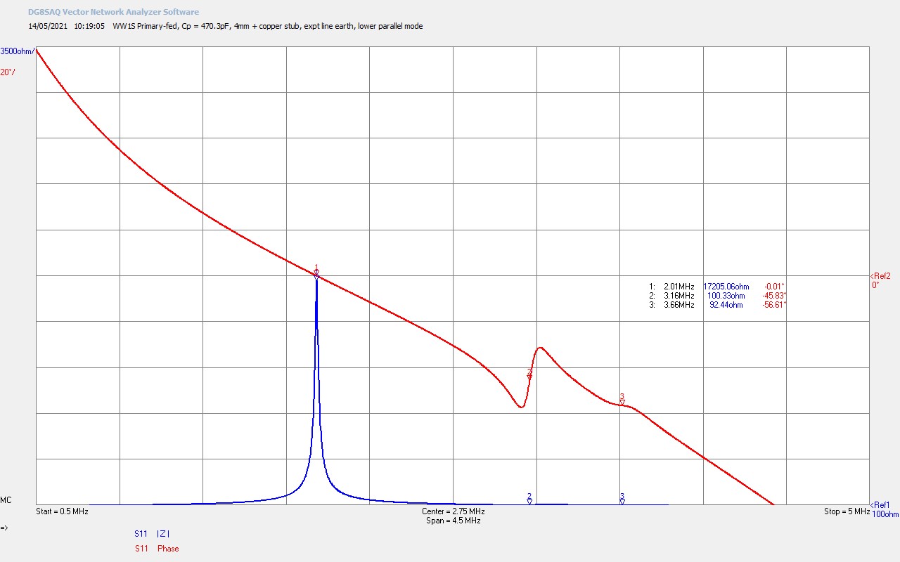
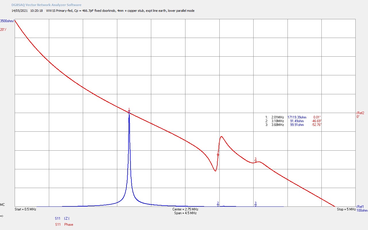
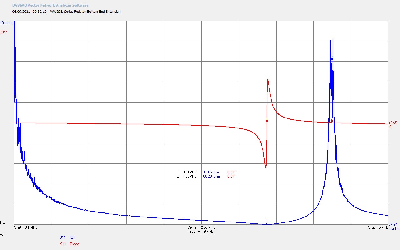
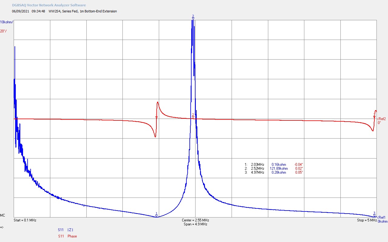
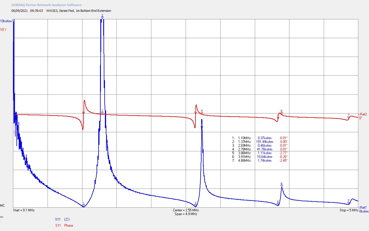
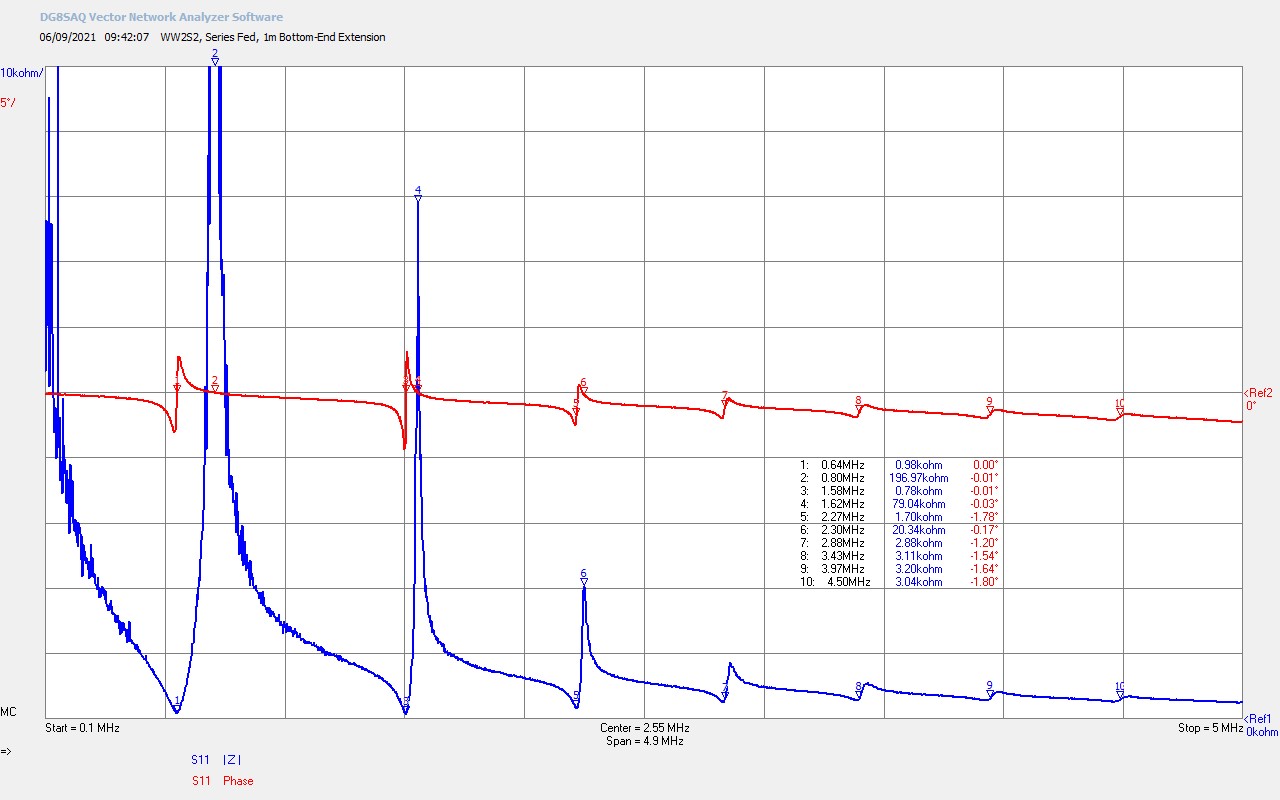
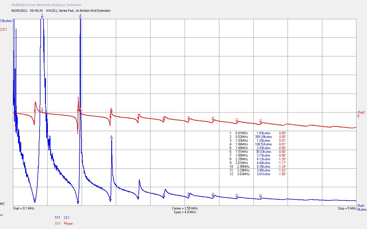
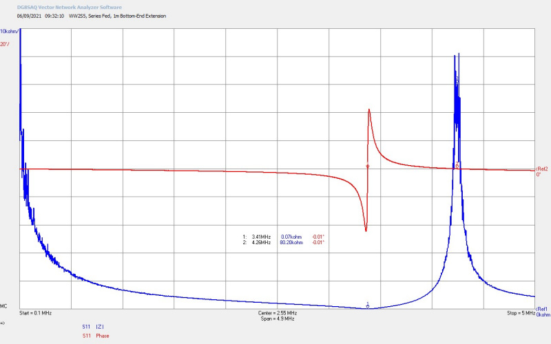
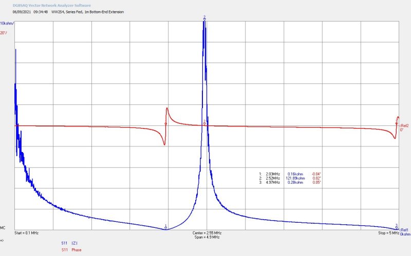
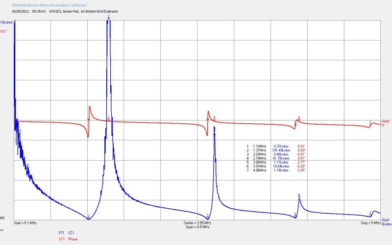
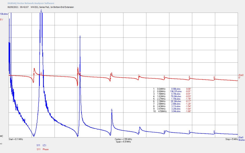
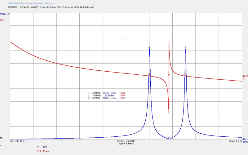
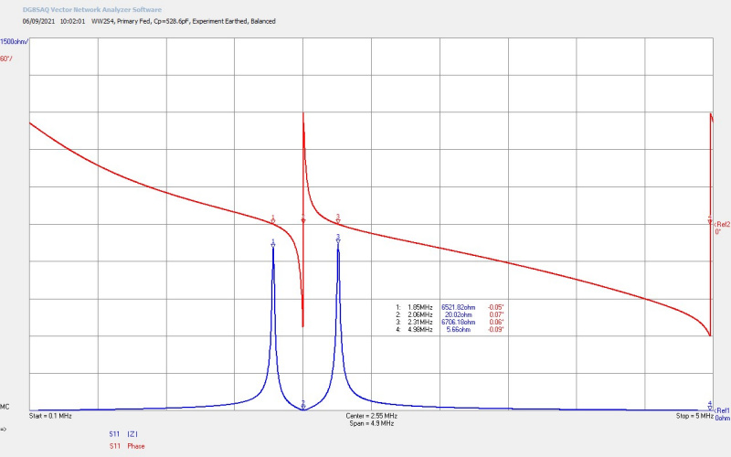
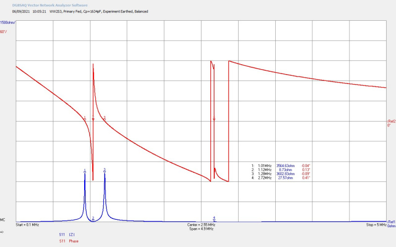
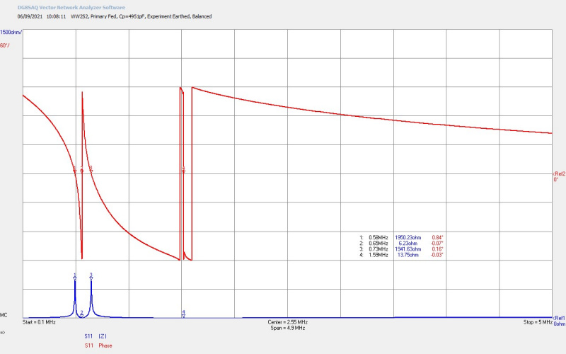
The frequency of this longitudinal mode is expected to be different from the transverse resonant frequency of the Tesla coil secondaries for both the transmitter and receiver coil in a matched and tuned TMT transmission system. Whilst impedance measurements on a TMT with a vector network analyser, reveal in minute detail the transverse mode inter-action of the various resonant circuits making up the overall system, it appears to show nothing of the properties of the longitudinal mode which lay outside of its measurement paradigm. The concept of a longitudinal wavefront where both Ψ and Φ are temporally and spatially in phase does not currently exist in modern electromagnetism, and there is not an instrument currently available for probing this mode and condition.

Still the question stands of how it is possible to dissipate power in a single wire load in a longitudinal cavity. To start to address this we must consider the coupling between modes in the local impedance change of the load. Whilst the longitudinal mode of transmission dominates in the single wire cavity, energy and hence power can be transferred to distant loads, with in principle very low loss. To dissipate as power in the single wire load, rather than transfer the energy in the longitudinal mode, a coupling or transformation to the transverse mode must occur, generating local voltage potential difference and local currents in the load, which in turn are consumed as power in the resistive load, such as the filament of an incandescent lamp. I conjecture that it is this transformation process between modes that is characteristics of a single wire transmission medium, and allows for loads to be powered in an open-circuit condition, something that would not be possible in classical electric circuit theory or practice.

Radiant energy as emission from a displacement event

Further to this transformation between the longitudinal and transverse modes in the open-circuit single wire conduction model, it is conjectured and to be explored as a central concern in this research that as the TMT system becomes more non-linear, and when properly arranged to be stimulated with high-power impulse transients, displacement events required to rebalance the local Ψ and Φ dynamics of the system give rise to radiant energy emanations. These emanations result in many of the observed phenomena presented in this post, and when properly arranged in timing, amplitude, and duration lead to a very wide range of perceptual phenomena that are both electrical and non-electrical in nature, and yet to be explored.

So it is maintained and to be explored that the ideal TMT system is one that is carefully balanced, matched, and tuned between the “transmitter” and “receiver” coils both for the longitudinal and transverse modes, such that the single wire transmission medium forms a low impedance, reciprocal, and high Q cavity, where Ψ and Φ are dynamically balanced and in equilibrium for the linear case. This ideal TMT system when subsequently powered by a highly non-linear, uni-directional, transient impulse generator of very high tension, will cause such large discontinuities in the local balance of Ψ and Φ that displacement, as an underlying guiding mechanism in the inner workings of electricity, will be called-forth to re-balance the local dynamics of the electrical system.

These displacement events generate emanations, or electrically based shock waves, that are themselves longitudinal in nature, where both Ψ and Φ are coherently locked in phase, creating an electrical pressure wavefront that emanates outwards from the primary event. the stimulated response of materials and forms which encounter the incident wavefronts may involve energy accumulation and storage, but also dissipation of energy through exertion of a physical forces, electromagnetic emission or absorption (light and dark), thermodynamic changes (temperature or pressure changes), or even perceptual changes of the surrounding medium.

The creation of such an experimental system to test these assertions on displacement and transference, transformation of the longitudinal and transverse modes, and transmission of electric power to distant loads with very low loss, represents a challenge equivalent to surmounting a mountain higher than the highest yet ascended.

Summary of the results and conclusions so far

In this post we have experimentally observed a wide range of phenomena that are usually attributed to those related to Tesla’s radiant energy and matter, and which have also been demonstrated and observed by other significant research efforts, including Dollard et al.[2]. It is clear from the experiments and observations that improvements to the TMT experimental system will facilitate a far more detailed and clear exploration of the underlying principles involved.

In considering the unusual observations of the experiment, and the accumulated understanding of the prior art through both my own collective work presented so far, and that of significant others[1-8], I have formulated a line of conjecture which combines both a philosophical and scientific approach towards the origin or source of these phenomena, and how that source could give rise, through fundamental principles and processes, to the materially observed effects of said experiments.

The formulated line of conjecture has the following key points:

1. The underlying origin or source of these phenomena resides in the inner workings of nature that, at the deepest conceivable level, is the result of the pressure of life’s intent, which in turn gives rise to the need for the natural and living world to evolve.

2.  The inner workings of electricity, as a part of the inner natural world, includes the undifferentiated fields of electric and magnetic induction Ψ and Φ, which act as one together in a fully inclusive manner, and which I refer to as displacement Q. Dollard[8] refers to a similar principle Q as the Plank, or total electrification, which for me reflects the same inner workings of electricity.

3. A displacement event is not normally observable in the differentiated dynamics of Ψ and Φ. This differentiation between Ψ and Φ, and all the implications of their temporal and spatial inter-action results in what science currently understands as the field of electromagnetism, and gives rise to all the phenomena that I refer to as transference.

4. A severe imbalance created between Ψ and Φ in a circuit system where the “need” or purpose of the circuit is clearly stated, and where equilibrium cannot be re-established through the process of transference, will call-forth the underlying guiding principle of displacement. The act of displacement coherently puts the differentiated Ψ and Φ into their proper temporal and spatial alignment, upon where transference can resume as the external and observable dynamics of electricity.

5. The result of a displacement event is to generate an emanation or shock-wave, which Tesla called radiant energy, that permeates the medium surrounding the displacement event, and extending out until all emanation energy is stored or dissipated by external transference of electric power.

6. The radiant energy emanation is a direct consequence and extension of the displacement principle, and equivalent to bursts of energy or electrification injected into the surrounding medium. Suitable collection or reception of this emanation, when introduced to a load suitable to balance the overall system, will make it possible to harvest this additional electrical energy for suitable means, provided the overall balance of the complete system and medium is not violated. This is similar to what Tesla[7] referred to “… it is a mere question of time when men will succeed in attaching their machinery to the very wheelwork of nature”.

7. The radiant energy emanation where both Ψ and Φ are coherently inter-acting leads to stimulated responses from material and forms in the surrounding medium, where the stimulated response may involve energy accumulation and storage, and also dissipation of energy through exertion of a physical force, electromagnetic emission or absorption (light and dark), thermodynamic changes (temperature or pressure changes), or even perceptual changes of the surrounding medium.

8. The extension of radiant energy into the surrounding medium, and when incident on another open single wire circuit with established purpose, will constitute a tributary event, and transferring the same electrical event properties to the tributary, where the quantity of transferred energy is equivalent to the load or need of the tributary circuit.

9. The overall balance and natural order of the electrical system will be maintained through the inner workings of electricity and the principle of displacement, and can be observed and experimented with. Ultimately the energy generated through displacement can be utilised where the natural order and balance is preserved by the utilisation. This is equivalent to where the load represents a need that is inclusive to the system, then the system becomes regenerative, and can self-sustain with energy being supplied to all loads in balance.

This post has opened and exposed many further questions surrounding all of the observed phenomena, the need for much more measurement detail, further design of a more optimal experimental system, and most importantly the verification, or otherwise, of each and every one of the conjectures made to explain and understand what might be the source and mechanism behind Tesla’s radiant energy and matter.

In the next post in this series I will be take a look at improvements to the TMT experimental apparatus that may lead to more detailed and clearly defined measurements to support aspects of the formulated line of conjecture.


1. Tesla, N., Apparatus for the utilization of radiant energy, US Patent US685957, Nov. 5, 1901.

2. Dollard, E. & Lindemann, P. & Brown, T., Tesla’s Longitudinal Electricity, Borderland Sciences Video, 1987.

3. Dollard, E. and Energetic Forum Members, Energetic Forum, 2008 onwards.

4. Lindemann, P., The free energy secrets of cold electricity, Clear Tech, Inc., 1st Ed, 2001.

5. Valentine, T., Man creates engine that consumes no fuel, The National Tattler, July 1, 1973.

6. Dollard, E., Etheric discharge from Eric Dollard’s tesla magnifying transmitter, Integratron, Summer 1986.

7. Tesla, N., Experiments with alternate currents of high potential and high frequency, Address to the Institution of Electrical Engineers, London, Feb. 1892.

8. Dollard, E., A common language for electrical engineering – lone pine writings, A&P Electronic Media, 2013.


Negative Resistance and the Self Generating Discharge

Negative resistance is a feature of the I-V characteristic of a discharge between two electrodes, and if correctly utilised can lead to unusual electrical phenomena within an electrical circuit. In this first part on this topic we explore the I-V properties of the negative resistance (NR) region of a carbon electrode spark gap (CSG), or carbon-arc gap. When the CSG is biased into the correct region, and combined with a switched (non-linear) impetus from the generator, the impedance of the circuit can be seen to reduce from the conventional short-circuit case, increasing the current in the circuit and intensifying the light emitted from an incandescent lamp load.

The negative resistance characteristics of a spark gap where explored and utilised by Chernetsky[1] in order to demonstrate what he called the self-generating discharge (SGD). The SGD is a state of discharge where he claimed that the energy consumed from the generator was reduced, yet the power dissipated in the load was increased, and where the additional energy in the electrical circuit was “inducted” from the surrounding medium, or what is commonly referred to as the Aether[2], a “gaseous” medium that is all pervasive throughout space, and is also considered to extend beyond the physical realm. As such Chernetsky claimed an over-unity (OU) phenomena where the total output power was greater than that supplied to the circuit by the generator. This experiment has been replicated by others, including Frolov[3], and Dawson[4], who also claim to have measured OU output. This sequence of posts investigates these principles, attempts to measure the claimed OU output, and further explore its possible origin. Ultimately the studied phenomena forms part of the continuing central research, of revealing the inner workings of electricity, and hence the displacement and transference of electric power.

When investigating over-unity claims good experimental and scientific method is critically important. I have found many situations where OU has been attributed to unusual phenomena without being supported by good and well measured experimental data. OU most often appears to arise in non-linear systems, which owing to their transient nature are also difficult to measure reliably, especially when output power is to be accurately measured. Input power is usually quite straight-forward to measure accurately as it is supplied by dc sources such as batteries and power supplies, or drawn from the mains utility supply which is a low-frequency sinusoidal input. In these cases electrical instruments can be arranged to accurately determine real and reactive input power.

Where the generator produces a non-linear output through switching, pulses, impulses, or chopping an otherwise dc or low-frequency sinusoid the dissipated output power can become a complex transient, with many high-frequency components, and many different phase relationships within the experimental circuit. When this is combined with high voltage and/or current magnification , multi-resonant elements, different transmission modes both transverse and longitudinal, cavity and termination effects, and hence significantly changing boundary conditions on the dielectric and magnetic fields of induction, the final accurate determination of output power, even with sophisticated instrumentation, is exceedingly complex, and can very easily lead to substantial errors and mis-understandings. As such, and due to the complexity of these measurements, the phenomena themselves are easily attributed to OU directly without further detailed assessment, and videos show the qualitative results of the phenomena without significant quantitative supporting evidence. It is not surprising given the often lacking experimental method, and lack of detailed supporting measurements, that conventional science so often holds a cautious and pessimistic view of the OU field.

Having stated this, OU is a very important exploration into the unknown, in the search for a truly sustainable, re-generative power source, and one that attracts wide and diverse forms of research and endeavour. My own research is orientated towards revealing the inner workings of electricity, and through co-operating with life’s natural processes, reveal the re-generative and inclusive nature of these under-lying processes. In this sense my own research strives for best scientific method, and well quantified supporting measurements, which then make it possible to either refute or support established claims, whilst making it possible for me to venture new claims of my own as to the origin, principle, and mechanisms of the explored phenomena. Often one experiment leads to another, as in the case of the experiment that is presented in this post. Whilst interesting phenomena are observed, explored, and measured, further experiments will be required to validate Chernetsky and others’ claims, that the additional energy in the OU experimental system is induced from a medium external to the electrical circuit. In my experiments in this post I find the additional energy that intensifies the luminance of the load, is drawn through the generator from the line supply, and directly as a product of biasing the CSG to utilise the NR properties in the abnormal glow region of the discharge.

Figures 1 show the experimental apparatus and circuit, and some of the different types of measurements taken as part of the experiments.

The generator for this experiment is a single HV transformer in the High Voltage Supply (HVS), the output is rectified and connected directly to one electrode of the CSG via an RF ammeter, (Weston 425 200mA FSD). The other electrode of the CSG is connected to a two lamp series incandescent load (2 x 25W = 50W) and then back to the other terminal of the HVS transformer. The CSG has fan assisted cooling, and is shunted in parallel by a 3kV 10A vacuum relay, which enables the CSG to be switched in and out of the circuit for impedance and load power comparisons. The fan and vacuum relay are driven by a low voltage 15V output provided again by the HVS. The input power to the HVS transformer is continuously measured using a Yokogawa WT200 Digital Power Meter.

The process of ionisation in the region between two electrodes with a high electric field, is well studied in the prior art[5]. Liberated electrons within the discharge region are accelerated by the electric field between the electrodes, and in the process of moving towards the anode cause further ionisation of atoms, leading to an electron avalanche effect known as a Townsend discharge.  Figure 2 below shows the typical current-voltage (I-V) characteristics for a Townsend discharge transposed from Abdelrahman et al.[6]. The negative resistance characteristics utilised in this experiment result from biasing the CSG to the correct region of this I-V curve, around the abnormal glow region between points D-E-F-G . The interesting and unusual phenomena presented in this experiment result from the reduction in circuit impedance, when the biased CSG is combined with a suitable load circuit (incandescent lamps), and driven from a non-linear transient high voltage generator at the line frequency.

The following video introduces the apparatus, experiments, and phenomena associated with the negative resistance of a CSG, and demonstrates aspects of the following:

1. A qualitative observation of the discharge produced in the CSG when biased into different regions of the I-V characteristic, including open-circuit, short-circuit, abnormal glow (D-E-F), and arc discharge (G) regions.

2. Adjusting and biasing the spark gap into the abnormal glow region to utilise the negative resistance properties within the electrical circuit.

3. The change in impedance of the circuit when switched between short-circuit conduction and spark gap discharge.

4. The change in circuit current and dissipated power in the load with switched impedance, and the effect on the input power to the generator from the line supply.

5. A comparison of adjusting and biasing the circuit when driven from a non-linear transient input, and a linear sinusoidal.

6. Measurement of the generator output using an oscilloscope both in the non-linear and sinusoidal cases, and showing the switching transients generated when the CSG is biased into the negative resistance region.

7. An experimental investigation of the I-V characteristics of the CSG using a Tektronix 576 curve tracer.

Figures 2 below show in detail some of the additional measurements made during the experiment including the overall impedance properties Z11 of the experimental circuit from the perspective of the generator, the different drive conditions applied from the generator, and the NR characteristics of the CSG measured on the Tektronix 576 I-V curve tracer.

To view the large images in a new window whilst reading the explanations click on the figure numbers below:

Fig 3.1. Here we look at the low frequency small signal input impedance Z11 from the perspective of the generator, using the HP4195A network analyser. The circuit was measured and compared in two conditions, firstly with the carbon electrodes touching at the ends forming a short-circuit, and secondly with the electrodes parted and the vacuum relay activated to shunt the electrode gap with a short-circuit path through the relay. In both of these cases the impedance measured was the same in magnitude and phase and shows that above 25Hz and up to 200Hz the circuit is completely resistive at a constant 379.5Ω, and constant phase of ~ 0° (-14.4 mdeg @ 100.1Hz). Below 25Hz will also be a continuous constant resistive impedance but requires considerably reduced resolution bandwidth to remove the measurement noise observed. A reduced resolution bandwidth in this case represents a considerably increased scan time for the measurement. This measurement shows that there are no unusual impedance characteristics at the base drive line frequency, no resonant characteristics, and that the circuit appears as a constant resistive load that results almost entirely from the cold resistance of the incandescent lamp filaments, 2 x 25W in series, (in the range 175 – 200Ω each).

Fig 3.2. Shows the HF small signal input impedance Z11 from the perspective of the generator up to 10Mc, using the HP4195A network analyser. The SCR in the HV supply creates a switched output from the incoming sinusoidal line supply, (see Fig. 3.1 here for detailed input and output waveforms), which means there are many higher frequencies present at the output of the HV transformer. This constitutes a non-linear transient drive to the experimental circuit, which is the summation of many higher frequencies, and hence higher frequency characteristics of the circuit impedance contribute to the overall circuit operation, and may play a part in the observed phenomena. This is then combined with the high frequency transient switching in the spark gap itself, which adds a much wider band of available frequencies, and the all important impulse-like currents in and around the abnormal glow discharge region.  We can see from this measurement that the resistive impedance rises gradually with frequency reaching ~ 434Ω @ 5Mc, and ~503Ω @ 10Mc. There are no significant features in the measured band, the circuit is not self-resonant up to 10Mc, and the overall circuit is largely resistive with a small amount of series stray inductance from the the wiring.

Fig 3.3. Shows the oscilloscope waveforms both for the input to the HV transformer at the output of the SCR (green), and the output of the HV rectifier at the input to the experimental circuit (yellow), where the circuit is set with the vacuum relay closed across the CSG. The SCR output shows how the line sinusoid is chopped into a small section, in this case part of the negative half of the cycle, providing pulses of input current to the HV transformer. The output of the HV rectifier is a voltage magnified pulse train up to ~ 2kV, and set at ~1.3kV peak for this experiment. This output level is sufficient to generate discharges in the CSG, whilst low enough to allow fine control of the I-V characteristics through electrode gap adjustment.

Fig 3.4. Here the vacuum relay has been opened and the CSG adjusted to utilise the NR region around the abnormal glow section of the I-V characteristics. The basic form of the waveforms are the same as in Fig. 3.3 with the addition of some impulse currents from discharges in the CSG, an increase in peak voltage at the output of the HV transformer ~ 1.8kV, and a slight increase in the “on” cycle of the SCR from ~ 4ms to 5ms. This corresponds to increased brightness in the lamp loads, an increased current in the experimental circuit from ~ 100mA to 125mA, and an increase in the power drawn from the line supply ~ 50W to 80+ W. The bias adjustment of the SCR remains the same as for the condition in Fig 3.3, yet clearly by operating the CSG around the abnormal glow region of its characteristics more power is drawn in through the line supply, reflecting a reduction in impedance in the experimental circuit below that of the normal short-circuit impedance at the CSG electrodes or through the vacuum relay. When the experimental circuit is biased at this point the region between the carbon electrodes is mostly dark and visibly discharge free, with the occasional momentary white flash as a discharge occurs across the electrodes when point G (Fig. 2) is reached.

Fig 3.5. Shows the I-V characteristics of the CSG as measured on a Tektronix 576 curve tracer. The advantage of a purely analog curve tracer like this is that negative resistance can be easily visualised through the unusual movement of the beam spot, which through the thickness and luminescence of the trace shows the speed of movement, and through the path of the spot often in arcs and loops, the unusual characteristics of NR regions and transitions. In this test the output power of the tracer is limited to 2.2W at maximum voltage bias of 1500V. With the current in the CSG restricted with a high series resistance (300kΩ) arc discharge does not occur, and the electrical characteristics can be explored prior to the arc discharge at point G. Here the voltage across the electrodes has been increased to the full 1500V output. At the transition voltage the gap enters the NR region and the trace rapidly sweeps negative in a wide arc before coming back toward the centre bias point at around 80mA of current, and still prior to arc discharge. The low luminescence of the arc shows the very rapid transition through this region, and the length of the arc right across to the far left of the screen, shows how the NR effect magnifies the  voltage across the high series resistance in the test circuit.

Fig 3.6. Here the output power of the tracer is set to 10W limit, with a series resistance of 65kΩ. At 1200V output the transition to the NR region is reached, but here the transition is even quicker which less voltage magnification to the left of the screen, and a tighter and more direct path to the same centre bias point of around 80mA of current prior to arc discharge. Without current limiting in the circuit the transition through the NR region is very rapid, which makes biasing a circuit to maintain characteristics at this point both tricky and mostly unstable, as could be seen in the video experiment. It is better to establish a circuit that oscillates around the NR region and hence utilising its unusual properties in a more stable manner, then trying to bias statically to one individual bias point within the NR region.

Fig 3.7. Here the output power of the tracer is set to 50W limit, with a series resistance of 14kΩ. At 1100V output the CSG transitions rapidly to arc discharge, indicated by the bright region at about 50V 80mA. The loops of the negative resistance region are just visible, and show now how rapidly the onset of arc discharge occurs when the circuit current is less restricted.

Fig 3.8. Shows the full development of the arc discharge curve at the maximum power output limit of 220W, with a series resistance of 3kΩ. The wide arcs of the negative resistance region are just visible, but the transition through this region is very rapid and in this case utilisation of that region would become very difficult as the characteristics of the CSG are dominated by the arc discharge. With the arc discharge fully developed in region G+ (Fig. 2) it is interesting to note that the impedance presented by the circuit is now higher then the short circuit case, the lamps are dimmer, and a lower current is drawn from the line supply. The impedance of the circuit can be further lowered by shorting the CSG with the vacuum relay, which increases the brilliance of the lamps to the CSG short-circuit case. The impedance of the circuit can be further lowered from the CSG short-circuit case by opening the vacuum relay, and adjusting the electrode spacing to bias the characteristics into the negative resistance region. At this point the lowest impedance of the circuit is presented to the HV supply, drawing the maximum current and hence power from the line supply.

The negative resistance characteristics in the discharge region, and the ability to adjust and utilise this region, appear to be strongly influenced by two material factors in the circuit:

1. The electrode material used for this experiment is carbon which shows a negative resistance region over an adjustable range. It is repeatedly possible, as demonstrated in the video, to adjust and maintain the CSG into the abnormal glow region of the curve and observe unsual phenomena in the circuit. When the carbon electrodes were replaced with tungsten electrodes it became very difficult to adjust the CSG into a region where the NR characteristics could be maintained. Adjustment to the correct bias could only be accomplished momentarily before reverting to the arc discharge region, or the open circuit condition. This suggests that the bias region for the abnormal glow is much narrower and hence much more difficult to select in a metal such as tungsten. As such the properties of carbon are identified as a more suitable material for the I-V characteristics that lend themselves to the utilisation of negative resistance within non-linear electrical systems.

2. The gaseous medium within the discharge region between the electrodes. In this first part on this topic, and for simplicity in the video, experiments were demonstrated with air in the discharge region, but considerably better results have been obtained when the electrodes are in a vacuum region or inert gas inside a glass tube. Two mechanisms have been tested to demonstrate this, the first a vacuum relay where the gap between the electrodes could be adjusted by applying a dc current to the relay’s exciter coil, and secondly a 1B24 TR cell, a cold cathode tube RF spark gap, where the internal gap can be adjusted by an external screw. A TR cell is a gas discharge tube which is used typically as an electronic switch, or as in the case of the 1B24, to protect the sensitive receiver of a radar system from damage by the strong transmit pulse. This method in radar is now long obsolete, the 1B24 being used in, and just after, the second world war. The tube used here has a manufacture date of May 1944 printed on the glass.

Figures 3 below shows the arrangement of the 1B24 TR cell which was used in experiments to enhance the phenomena presented in this post.

In the case of the vacuum relay it was found that a very small gap could be controlled by adjusting the dc current in the relay exciter coil. At a certain level of bias the contact would start to switch between closed and a very tiny gap, both exploiting the negative resistance in I-V characteristics, whilst introducing another transient switching source in the circuit. In this case the overall resistive impedance in the circuit fell considerably lower than that experienced with the correctly biased CSG. The current in the secondary circuit went up as far as 200mA, the lamps where illuminated with a very high brilliance, and the input power drawn from the generator increased considerably to reflect this rapid decrease in circuit impedance. This bias method and utilisation of NR whilst intensified, was difficult to maintain, and would quickly destabilise to normal circuit impedance. However, this experiment shows that the utilisation of NR properties is strongly dependent on the degree of transient switching and hence non-linearity in the circuit, and combined with a clean discharge region, in this case the vacuum relay contact gap, considerable intensification of the phenomena is possible.

Summary of the results and conclusions so far

The phenomena observed in this experiment and demonstrated in the video, and combined with additional supporting measurements,  appears to result from a reduction in circuit impedance below that of a short-circuit condition, when the CSG is adjusted into the negative resistance region surrounding the abnormal glow section of the I-V characteristic. When adjusted to this region, and combined with a non-linear transient drive from the generator, the overall impedance of the circuit drops, and the current rises as more power is drawn from the generator. In this experimental case the increase in brilliance of the incandescent lamps results from additional power drawn from the generator, over and above that drawn when the CSG is directly short-circuited by the vacuum relay. From this we can ascertain that the negative resistance region of the CSG reduces the overall circuit impedance presented to the generator in non-linear transient cases. In this experiment there is no evidence of additional energy being drawn into the circuit from any source other than the generator, and all changes in energy can be accounted for by measurement of that supplied into the HV supply, and that dissipated in the load.

In comparison, when the HV supply was driven using a linear sinusoidal from a variac, rather than a non-linear switched SCR controller, the phenomenon could not be adjusted, observed, or measured in the same experiment, and the impedance of the circuit under all conditions using the CSG is greater than the short-circuit of the vacuum relay, or carbon electrodes. From this it is clear that to utilise the unusual properties of negative resistance they must be combined with a non-linear impetus, which also suggests a process that may be related to underlying displacement events. It is always in the presence of a non-linear condition that the mechanism of displacement can be engaged or observable within the electrical properties. It appears to surface in non-linear scenarios where the boundaries of the dielectric and magnetic fields of induction would lead to a discontinuous condition in the electrical properties of the circuit. It is conjectured that displacement appears to “act” in order to rebalance this discontinuous condition and restore dynamic equilibrium between the induction fields within the circuit.

With regard to the phenomenon observed in this experiment, it is conjectured that the apparent reduction in circuit impedance below that of a short-circuit primarily results from a coherent inter-action between the dielectric and magnetic fields of induction. The analogy is drawn to both the superconducting state in metals at low temperature[7,8], and also to ballistic electron transport in a high mobility electron gas[9], also at low temperature. In the case of the superconducting state two electrons became weakly bound together through exchange of a lattice phonon. In so doing they form Cooper pairs where the coherent phonon exchange extends across the entire material on a macroscopic scale. This coherent phonon exchange, and subsequent binding together of Cooper pairs, leads to a band-gap opening in the conduction band of the material, and hence electron-pairs can traverse the dimension of the material without scattering in this band. In this way conduction of a current via electron movement through the superconducting material has zero resistance, and is considered to be coherent.

In the second case of ballistic electron transport, the electronic energy band structure of the semiconductor is so arranged to provide a quantum well, narrower than the phonon wave number, at the fermi level within the well. This confines electrons to a 2D sheet in the well, reducing scattering and increasing the mean free path. Further confinement laterally leads to a 1D wire where the scattering with the lattice is further reduced and the mean free path of an electron becomes longer than the injection contacts at either end of material. In this case, and at low temperature, electrons can travel ballistically from one terminal to the other (e.g. in a quantum wire channel). The ballistic conduction reduces the resistance between the contacts below that normally expected for the diffusive condition, since the scattering with the lattice has been reduced to a point where the electron path between the contacts can be considered as coherent.

In both of these analogies reduction in impedance of the transmission medium is considered the result of a coherent conduction process. In the experiment reported here I conjecture that the reduction in impedance results from the coherent inter-action of the dielectric and magnetic fields of induction, where that coherent configuration is brought about by a displacement event. The displacement event is in itself revealed through the non-linear drive to the experiment, and “mixed” through the negative resistance properties of the CSG. The final product of the displacement event through the negative resistance characteristics, is to re-balance the electrical dynamics of the circuit by coherently aligning the dielectric and magnetic fields of induction yielding a reduced circuit impedance. This conjecture, based on the results so far, requires considerable further work to establish its scope of validity, and would also ideally benefit from a suitable mathematical treatment, when such a form of mathematics is available to describe the properties and processes under exploration.

For further exploration and discussion on the results and phenomenon from this experiment please see the Energetic Forum[10].

In the experiments of Chernetsky[1], and others[3,4], the SGD occurred when the carbon electrodes were adjusted, presumably, into the negative resistance region of their I-V characteristics. The generator for this experiment was a switched fly-back transformer, (transient driven), between 25-100kc, and the secondary circuit incorporated a tank capacitor charged from a half-wave rectified output from the secondary coil of the fly-back. The load was formed with incandescent lamps in series with a carbon electrode gap, and connected in parallel with the secondary tank capacitor. When the carbon arc gap was properly adjusted in the experimental circuit, the current supplied to the fly-back primary was seen to fall, whilst the lamp load was illuminated with greater brilliance, and no discharge arcs where visible between the carbon electrodes. The additional energy in the circuit to maintain the brilliance of the lamps was attributed to energy drawn into the circuit from the Aether and the circuit is claimed to be OU in performance.

The experimental circuit explored in this preliminary investigation of negative resistance is different to that of Chernetsky and others for the following main reasons:

1.  It operates at the line frequency of 50Hz, much lower than the 25-100kc of the fly-back transformer.

2. It does not include a tank capacitor in the secondary, which made lead to additional resonant circuit and/or magnification phenomena in the secondary, and possibly cavity effects and hence longitudinal modes formed between the secondary of the fly-back and the external circuit.

3. A bridge rectifier is utilised instead of half-wave rectification of the secondary output.

Differences 1 and 2 may certainly be significant to the overall result and performance of the circuit. On this basis it is not possible yet to support or refute the OU claims for this circuit. Certainly the non-linear negative resistance phenomena explored in this experiment does not result in an OU condition. In the next part of this experimental sequence the same CSG is used in a circuit equivalent to that presented by Chernetsky and others, and its overall performance measured in detail.


Update

A recent replication of this experiment by Bierbaumer[11] demonstrates that in a very similar experimental arrangement, the increased light intensity observed in the lamps, and the measured additional power drawn from the supply, is most likely to occur due to a slight preferential phase shift between the voltage and current waveforms in the SCR envelope. In this experiment the phase shift appears to be brought about by impulse noise generated by discharges in the carbon spark gap, which effects the triggering conditions of the SCR in the most basic trigger circuit. It is subsequently demonstrated that improvement of the SCR triggering circuit, to make it less susceptible to impulse noise generated by the spark gap, suppresses the observed phenomena of increased lamp intensity and additional consumed power.

Bierbaumer also uses an alternative approach to the replication of the negative resistance I-V characteristics, using a digital and analogue oscilloscope in X-Y mode, and series connected carbon-silicon spark gaps. In this experiment he demonstrates anomalously high “shoot-through” or impulse currents, which are considerably larger than expected from the measured circuit impedance, and appear to occur right at the point where the spark gap transitions between the abnormal glow region at region E (ref. Fig. 2 at the top of the post), through the transition from glow to arc at region F, and finally into the arc at G. The result of this demonstration appears to show that despite the considerable current limiting in the discharge circuit from a low inductance, high resistance load, high intensity impulse currents and the associated magnetic induction field can be generated around the negative resistance region of the carbon-silicon spark gaps.

In my own experiments I have measured similar large anomalous impulse currents in the I-V characteristics when the previously mentioned B1B vacuum relay,  or the 1B24 cold cathode RF spark gap, were connected in parallel with the existing carbon-arc gap, and adjusted to the critical region on the I-V characteristrics at E-F-G. The result was much larger than expected impulse currents that could not be accounted for through SCR waveform phase relationship changes, or the measured impedance of the experimental circuit. The generation of excess impulse currents is an area that requires further investigation and careful quantitative measurement to establish if it is directly the result of negative resistance characteristics, or part of other non-linear phenomena that can arise from displacement of electric power.


1. Chernetsky, A., About physical nature of biological energy phenomenons and its modeling, All-Union Correspondence Polytechnical Institute, Moscow, 1989.

2. Whittaker, E., A History of the theories of aether and electricity, Longman, Green and Co., 1910.

3. Frolov, A. Self-generating electrical discharge, Pegasus Research Consortium, 1996.

4. Dawson, D. Notes on the Impulse discharge, Post #2765, Energetic Forum, 2020.

5. Little, P., Electron-emission – Gas discharges, Handbuch der Physik XXI,  Springer-Verlag, 1956.

6. Abdelrahman, M. & El-Khabeary, H., Study of Three Different Types of Plasma Ion Sources, Plasma Science and Technology, Vol.11, No. 5, Oct. 2009.

7. Bardeen J. & Cooper, L. & Schrieffer, J., Theory of Superconductivity, Physical Review, Vol. 108, pg. 1175, 1957.

8. Marsh, A. & Williams, D. & Ahmed, H., Supercurrent transport through a high-mobility two-dimensional electron gas, Vol. 50, No. 11, Physical Review B (Rapid Communications), September 1994.

9. Marsh, A., Superconducting contacts and Supercurrent Flow in a GaAs/AlGaAs Heterojunction, Ph.D. Thesis, Cambridge University, July 1995.

10. Forum Members, Eric Dollard Official Forum -> Eric Dollard, Post #2807 onwards, Energetic Forum, 2020.

11. Bierbaumer, W., Negative Resistance and the Self Generating Discharge – Experimental Replication, YouTube, 2021.


The Wheelwork of Nature – The Golden Ratio Discharge

Sooner or later research into the underlying nature and principles of electricity must inevitably lead to those larger philosophical and esoteric questions surrounding the origin and purpose of life, its mechanisms that constitute the wheelwork of nature, and our purpose and part to play as very small cogs in this grand design. I have in previous posts started to tentatively touch-on and develop my own current understanding of the wheelwork of nature through ideas, designs, experiments, and conjectures regarding displacement and transference of electric power. This post is the first in a sequence looking at experiments in electricity which reveal or suggest clues about this underlying wheelwork, with the associated phenomena and results, their possible origin and purpose, and how we may form a synchronicity with this wheelwork, and hence benefit from a journey that increases our knowledge and awareness of our-self and that of the great mystery or grand design. This first post in the series looks at the wheelwork of nature – Golden Ratio or Fractal “Fern” Discharge experiment, along with observations, measurements, and interpretation.

For a summary recap on how I see the principles of displacement and transference of electric power, and the conjectures that I have already made based on the experimental work reported so far, I recommend reviewing Displacement and Transference of Electric Power, Tesla’s Radiant Energy and Matter, the Transference of Electric Power category, and the overall Introduction to this website. The essence of this definitive journey was so well articulated by Nicola Tesla, in what is for me one of his greatest statements, and which should have both enormous and far reaching impact on the efforts of our research into the wheelwork of nature, and the underlying principles and mechanisms that constitute this wheelwork: “Throughout space there is energy. Is this energy static or kinetic! If static our hopes are in vain; if kinetic – and this we know it is, for certain – then it is a mere question of time when men will succeed in attaching their machinery to the very wheelwork of nature.”, Tesla[1].

In this statement Tesla shares his unwavering believe that it is only a matter of time until we will attach our experiments, apparatus, and machines directly to the wheelwork of nature, not if, but when. And how close have we gotten to this vision ? It would seem to me that in the field of electricity research as a whole, a little progress may have been made, but we still seem quite far from accomplishing this monumental task of understanding, and making a shift of focus from measuring voltages and currents on the bench in an apparatus seemingly unrelated to the wheelwork of nature, to an inclusive and intuitive approach where the workings of our apparatus reflect the underlying wheelwork in the natural world. In order to accomplish this I believe it is a necessity to work at building a bridge between the Philosophical/Esoteric and Scientific disciplines, through looking at electrical phenomena with fresh eyes and with a mind open to grasping an understanding of the underlying principles and mechanisms across seemingly diverse and seemingly different disciplines.

Science in our current times considers the field of electromagnetism to be almost entirely understood and explained, with any further exploration aimed at the successive dissection of smaller and smaller detail. Whilst science has developed a successful model to explain the outer form of electromagnetism, and the principles and equations required to utilise this field in engineering, this is only a good observation and measurement of the outer form, with all the underlying quality and richness of this subject yet to discover. In this post I intend to start this process by including conjectures regarding the experimental results and phenomena that cross these multi-disciplinary boundaries, and hence take those small steps on the long road to building a bridge of understanding and ultimately greater awareness of our own inner world and that of nature. Whilst this will not appeal to some that read this post, for others it may trigger ideas and different ways to consider and interpret the results of our experiments, and open the possibility for new discovery of the inclusive hidden world ever present in our daily endeavours.

In understanding Tesla’s statement it would seem important to first get a grasp on what constitutes the wheelwork of nature, and how we go about attaching our endeavours to it. In an effort to impart some of what I think and feel on this topic I will use the experiment to be presented in this post as an example, which with all best intent may shed but a little light on the vast unknown darkness that lies ahead of us on this journey. In this post I will be looking experimentally at a Tesla coil (TC) experiment first demonstrated by Eric Dollard[2], using his Integratron apparatus in 1978. The apparatus generated a “fern” like discharge, one quite distinctly different from the normal range of “lightning” like discharges emitted by the majority of TC apparatus and experiments.

This “fern” discharge is particularly interesting when viewed as a form of fractal, which may also have golden-ratio geometry associated with it, where the filaments and tendrils formed along the primary streamers have an impulse like nature, are momentarily transient and orthogonal in nature, and the overall growth and pattern of the discharge is reflected in naturally occurring forms. These combined together indicate to me that this experiment may lend itself well to exploring and gaining a better understanding for the wheelwork of nature, or in other words, the underlying principles and mechanisms that lead to the generation of this exciting result. Since Eric’s original experiment there appears to be little public knowledge available on the details of how to generate this phenomena, the apparatus and operating conditions required to call-forth or reveal this type of discharge, and considered analysis and conjecture on how this phenomena occurs, and what it can show and tell us regarding the wheelwork of nature.

In this post I will be experimentally demonstrating this phenomena in a two-part video experiment, looking in detail at the apparatus and setup required to generate this discharge, along with analysis of the TC impedance characteristics, and some preliminary consideration as to the meaning and relevance of this phenomena. As way of introduction directly to the results, figure 1 below shows a side-by-side comparative image of Eric’s original experimental result, and the discharge obtained in the experiment presented in this post. It can be seen that the discharge in nature and form are equivalent.

If we study these images carefully looking at the similarities and differences then we start to see a most astonishing result, that many of the features occur in the same proportion and with same intrinsic detail. The primary tendril grows vertically in the centre and is essentially the same form with the same curve, sub-tendrils emerge at similar points along its length, and micro-filaments are ever-present orthogonal to the main structure. The second main tendril to the left, (allowing for some 3D rotation on axis), follows a similar pattern with corresponding bifurcations and sub-tendrils along its length, as do the other smaller tendrils and filaments around the breakout point.

When considering electric discharges, what are the chances that two different experiments, with different coil systems, materials, and components, and different generators operated with unknown differences, will produce two discharges that are so very similar in geometric structure, form, and nature ?  If the nature of the discharge is essentially random both spatially and/or temporally, then it would seem most unlikely, but if there are underlying guiding principles at work then it would seem quite possible, provided the same set of principles are involved in both experiments. These underlying guiding principles I am referring to as the wheelwork of nature, and this experimental series is intended to see what can be discovered, understood, and applied in attempting to attach these experiments to the very wheel work of nature!

This experiment uses the Plate Supply, yet to be covered in detail in the Tube Power Supply Series, as the high tension generator, combined with a dedicated coil system consisting of a single Russian GU-5B power triode, and a nominally designed 3.5Mc conventional style Tesla coil. The TC is designed and arranged with a tightly wound and coupled primary and secondary coil geometry, specifically intended for high voltage magnification and the generation of discharge streamers. The design deliberately steers clear of any design proportions involving the golden ratio or optimisations suitable for the transference of electric power in a TMT system, and this is intended in order to emphasis the quality of the experimental result generated by underlying principles in the wheelwork of nature, rather than outer geometric proportions arranged to demonstrate any particular result.

Part 1 of the video experiment demonstrates and includes aspects of the following:

1. Introduction to the wheelwork of nature experimental series based on Nicola Tesla’s famous quotation, and Eric Dollard’s original “fern” discharge experiment.

2. Brief Introduction and consideration of the importance and implications of the bridge between the Philosophical/Esoteric and Scientific disciplines, through grasping an understanding of the underlying principles and mechanisms of the wheelwork of nature.

3. Overview of the tube plate supply generator, GU-5B coil system, and Tesla coil to be used in the experiment.

4. Design and construction considerations important to a high-frequency 3.5Mc Tesla secondary coil, suited to discharge experiments in the wheelwork of nature.

5. Primary coil drive circuit apparatus using a series feedback class-C Armstrong oscillator, tuned to the lower parallel resonant mode at 2.6-2.9Mc, and matched for best power transfer from the generator.

6. The “fern” discharge phenomena at various generator power output levels from 100W – 2.2kW

7. Observation of the characteristics of the “fern” discharge including fractal like self-repeating, self-similar tendrils, golden-ratio like proportions in the tendrils, orthogonal emitted sub-tendrils, and orthogonal displacement like micro-filaments and fibres.

8. Symmetric and reflected discharge patterns in geometric space, including tendril growth and extinction, and temporally based non-random, sequenced and repeating discharge patterns indicative of a defined “dance” routine.

9. Conjecture of an underlying dynamic and guiding pattern and order to the “fern” discharges, and hence a tantalising and astonishing view of part of the underlying mechanisms of the wheelwork of nature.

Part 2 of the video experiment demonstrates and includes aspects of the following:

1. Experimental variations to part 1 of the experiment in order to see if the nature and form of the fractal “fern” discharge could be changed to another form

2. Tuning the coil system down to 2.1Mc on the lower parallel resonant mode, whilst observing the discharge form.

3. Tuning the coil system up to 4.0Mc on the upper parallel resonant mode, whilst observing the discharge form.

4. Tuning the coil system across the transition between the lower and upper parallel resonant modes, whilst observing the discharge form.

5. Changing the blocking/tank capacitor at the output of the plate supply from 25nF 25kV to 30uF 8kV.

6. Changing the plate supply output from a bridge rectified waveform with blocking capacitor, to a raw unrectified waveform with no blocking capacitor.

7. Adding a toroidal top-load to the Tesla coil and retuning the lower parallel resonant mode to 2.28Mc, whilst observing the discharge form

8. Replacing the single GU-5B power triode with parallel connected dual 833C power triode tubes.

9. Observation using the dual 833C triodes at the upper parallel resonant mode at 3.9Mc of a tighter and more rounded fractal “fern” discharge, with shorter, more rounded, and more numerous tendrils.

Figure 2 below shows the schematic for the experimental apparatus used in the video experiments. The high-resolution version can be viewed by clicking here. The tube plate supply is not included here and will be covered subsequently in another post.

Principle of Operation and Construction of the Experimental System

The plate supply is configured with two high voltage (HV) microwave oven transformers connected in series to produce at maximum load 4.2kV @ 800mA, and up to 6.5kV unloaded. From the GU-5B datasheet the maximum anode potential is rated at 5kV for frequencies less than 30Mc, so two transformers in series are adequate when driving the experiment in CW (constant wave) mode. Although not covered in the datasheet the GU-5B can withstand considerably higher anode voltages up to ~ 8-9kV when driven in a pulsed mode with a low duty cycle, which considerably improves the forward pressure supplied to the primary coil. In this experiment I use only CW mode in order to simplify the generator drive characteristics, and to minimise variations in the circuit that could further mask the origin of the discharge phenomena to be explored.

The output of the HV transformers can be configured to a variety of different stages in the plate supply, including raw output, bridge rectified, or level shifted. In this experiment I predominantly use the bridge rectified output to provide an all positive unipolar electrical pressure to the coil system. For experimental variation I also demonstrate the raw output of the transformers which supplies the SCR controlled portion of the sinusoidal transformer output, up to the full sinusoidal output at maximum input power. In this experiment the purpose of the generator is to supply sufficient voltage swing across the primary to ensure high voltage magnification at the top-end, whilst also supplying adequate current in the primary circuit so there is strong magnetic induction field coupled between the primary and secondary coils, and hence the discharges are hot, white, thick tendrils that can be readily observed, measured, and studied.

At the output of the plate supply is the blocking/tank capacitor which is intended to protect the plate supply components, such as the semiconductors in the bridge rectifier and the power control SCR, by preventing voltage spikes and oscillation from the primary resonant circuit from being reflected back into the power supply. This can happen very easily e.g. if there is a poor impedance match between the generator (tube anode) and the Tesla coil, or during tuning experiments the tube stops oscillating, or oscillation becomes unstable between the upper and lower parallel resonant frequencies. In the basic experiment a 25nF 25kV pulse capacitor is used as the blocking/tank capacitor at the output of the power supply, which is raised right up to 30µF 8kV for the variation experiments.

The positive output from the blocking capacitor is fed via a short length of AWG 12 silicon coated, micro-stranded, low-inductance cable to the primary coil circuit, which consists of the 7.5 turn primary coil and a KP1-4 10kV vacuum variable capacitor 20-1000pF connected in parallel. The connections between the primary coil and the primary tuning capacitor are AWG 8 silicon coated, micro-stranded, low-inductance cable, and the inter-connections on the top of the coil system on both sides of the primary coil are made with copper busbars and 4mm high voltage terminals. The other end of the primary coil circuit is connected directly to the anode of the GU-5B tube, again using the same AWG 12 low-inductance cable.

The complete primary circuit from the plate supply back to ground is connected using low-inductance heavy duty cable in order to reduce inductive reactance losses in the primary circuit, and hence maximise the potential difference swing across the primary coil. In this experiment the ground connection is simply the line earth provided to both the plate supply unit, and the coil system unit. For simplicity, and hence maximum clarity on the experimental phenomena, no rf ground was used separately to the grounding of the units to the line earth. So the return line for both the generator drive via the GU-5B and plate supply, the secondary coil bottom-end, and the pickup coil bottom-end are all connected directly together by the line earth.

In order to simplify the TC drive from the generator the GU-5B is arranged as a Class-C Armstrong oscillator, which derives feedback from the secondary coil resonation via a 4-turn pickup-coil which is positioned under the primary coil, and isolated from the primary and secondary by a nylon plastic platform at the base of the TC. The pickup coil feeds the charging circuit in the grid circuit of the tube. Correct polarity and selection of the grid capacitor combined with the parallel discharge rheostat will enable the tube to oscillate at the selected and tuned parallel resonant mode.

The principle of operation of this form of tube driven series feedback oscillator is covered in detail in the post Vacuum Tube Generator (811A) – Part 1. In a tube driven primary coil circuit it is important to maximise the voltage swing across the primary coil, and at the top-end of the tube anode, whilst ensuring maximum power transfer from the generator to the primary circuit. This is accomplished by ensuring that the anode resistance of the tube during operation is arranged to be as close to the resistance presented by the primary coil at either the upper or lower parallel resonant frequency that is being used. This is then fine-tuned for optimum power transfer by adjusting the grid feedback bias.

When driven by this type of oscillator with feedback directly from the secondary coil resonation, the oscillation will centre around one of the two parallel modes presented by a tuned primary-secondary Tesla coil. The different modes that result from the close coupling of a primary and secondary coil, are well covered, measured, and explained in Cylindrical Coil Input Impedance – TC and TMT Z11. The design of the Tesla coil itself for this experiment will be covered next, along with the usual small signal ac input impedance characteristics Z11, in order to understand the TC impedance properties and characteristics, the best match and driven point for the experiment, and the range of tuning that is available for variations in the experiment.

Figures 3 below show a range of pictures of the experimental system, including some of the construction details of specific interest, and some of the variations to the initial basic setup of the experiment.

Secondary Coil Design, Considerations and Construction

The design of the Tesla coil always starts with the characteristics of the secondary coil to define its series fundamental resonant frequency ƒOSS), and the geometry of the coil suitable for the type of experiment to be undertaken. Design considerations for Tesla coils are considered in detail in the post Tesla Coil Geometry and Cylindrical Coil Design. For this experiment ƒSS without any top-load or wire extension, was designed nominally to be in the 80m amateur radio band at 3.5Mc. The geometry for the coil is to be tightly wound with many turns e.g. > 100 in order to maximise magnification of the dielectric induction field across the secondary length, and which is well suited to discharge streamers of a good length and intensity at the break-out point at the top-end of the secondary coil. When grounded at the bottom-end, which represents a lowering of the bottom-end impedance, the secondary will appear as a λ/4 resonator where the series mode resonant frequency ƒSS is dominated by the wire-length and series self-capacitance of the coil. The accompanying parallel resonant mode will be at a higher frequency than the series mode, and is dominated by the inter-turn inductance and inter-turn capacitance of the coil.

The tightly wound secondary geometry with many turns has an aspect ratio of 5:1 so the coil is tall and narrow and well suited to high voltage magnification at the top-end. A suitable piece of 3″ diameter irrigation pipe was available in the workshop which had a measured diameter of 76mm.  The complete design of the coil deliberately avoids any golden-ratio proportions in the aspect ratio of the secondary, the conductor diameter to the conductor spacing of the windings, and the drive parallel resonant mode frequency to the series mode frequency. This intentional omission of the golden-ratio is intended to simplify the interpretation of the experimental results, by removing considerations of influences that may arise from golden-ratio relationships between the experimental apparatus and the underlying principles of the wheelwork of nature. Subsequent variations to the basic experiment can then be added e.g. a Tesla coil that includes golden ratio proportions but has a nominally designed equal series fundamental resonant frequency at 3.5Mc, in order to compare the results and observed phenomena for golden-ratio influences and/or principles.

Tccad 2.0 was used for a rapid and approximate indication of the electrical and resonant characteristics of the secondary coil, the detailed results of which are shown below in figure 4. The wire selected for the secondary coil is a good quality silicone coated multi-stranded conductor, the silicone coating being very good both thermally, and as an insulator to prevent breakouts and breakdown from the upper turns of the coil to the lower ones. A standard electrical wire size 1mm2 (1.1mm diameter) with a total diameter of 2.45mm (nominally 2.5mm in the specification) was found to be ideal for the design proportions, and also avoids any golden-ratio winding proportions in the design.

The parameter “Winding Height of Secondary Coil” on the turn period of 2.45mm, (“Wire Diameter” 1.10mm + “Spacing Between Windings” 1.35mm), was used to adjust the number of turns in the secondary until the “Approximate Resonant Frequency” was closest to the desired 3.5Mc, and in this case was calculated to be 3493.87kc. Since we are running the secondary coil without a top-load, and with many tightly coupled turns, the “Secondary Quarter Wavelength Resonant Frequency” will be far from that required, in this case at 2025.26kc, the difference in the two also indicating that there will be a reasonably wide difference in frequency between the series and parallel resonant modes of the secondary.

In this experiment the secondary coil is to be driven magnetically coupled to a primary coil as per a standard and conventional Tesla coil arrangement, and which is well suited to being driven by variably tuned upper and lower parallel modes by a feedback oscillator. Since a spark gap generator is not being used, which requires very high oscillatory currents in a tuned primary tank circuit, the secondary coil could be driven directly by the generator without a primary coil, and at the series fundamental mode. This would require an output transformer to transform the high plate resistance of the tube to the low series resistance of the secondary coil at resonance. Whilst this latter method is a more efficient and matched drive at the series resonant frequency, it also adds additional complexity in the output matching transformer, and the controlled output frequency from a linear amplifier drive.

Primary Coil Design, Considerations and Construction

For this experiment, simplicity of Tesla coil drive was selected in order to minimise influence on the final results, and hence a standard primary-secondary Tesla coil arrangement was used. The primary coil is a standard tightly wound multi-turn geometry with a heavier gauge wire than the secondary coil, nominally again a good quality silicone coated, multi-stranded conductor, and of a standard electrical wire size of 2.5mm2, and with a total diameter of 4.0mm. The diameter of the coil was set at 130mm using acrylic tube, which results in a reasonably tight magnetic coupling to the secondary, and hence good power transfer from primary to the secondary, combined with excellent voltage magnification properties, and all very well suited for large and powerful discharges at the top-end. The number of primary turns was defined as a balance between the magnetic coupling and the tuned parallel mode frequency when combined with the KP1-4 primary tuning capacitor. 7.5 turns was found as an optimal balance between the magnetic coupling, a suitable tuning range of the primary variable capacitor to cover both the upper and lower parallel modes, and physical connection of the electrical outputs to the input busbars on both the +ve and -ve sides.

This form of primary is very well suited to a generator which is based on a driven oscillator or linear amplifier. In this type of generator which is often vacuum tube based, (or semiconductor based), the drive frequency of the generator is arranged to be at a specific point in relation to ƒSS dependent on the series or parallel mode to be driven, and the primary circuit consisting of the coil and parallel tuning capacitor are not arranged to be resonant to the selected mode of the secondary. In this case the primary currents are much lower than in a spark-gap primary tank circuit, but nonetheless transfer maximised power from the generator to the primary based on a reasonable impedance match of the tube plate resistance to the high parallel resonant mode resistance. In addition, no attempt has been made to design the primary circuit for equal weights of conductor with the secondary coil, thereby also simplifying the included design principles, and in principle simplifying the interpretation of the measured results.

From repeated operation of the coil system in discharge experiments, the gauge and design of the primary has been found to get quite hot when running at high input powers up to ~ 2.5kW, and for sustained time periods e.g. > 1-2 minutes in CW mode. Pulsed mode improves this further, but was not used in the basic form of the apparatus, to again not complicate the possible interpretation of the experimental results. Later experiments use a re-designed primary of the same diameter but with much heavier gauge windings e.g. AWG8 or 12 silicone coated micro-stranded wire, and a naturally convection cooled coil wound on support posts, rather than a solid acrylic tube. Details of this improved primary coil will be presented in subsequent experimental posts.

Overall, the design of the primary and secondary, both electrically and mechanically, were arranged to be able to cope with a high drive input power from the plate supply, which provides hot white discharge streamers at the top-end of the secondary. These powerful discharges of good length and definition make it much easier to observe, identify, and study their form and geometric structure over extended time periods, and the designed apparatus lends itself directly to the purpose of uncovering the wheelwork of nature. This is in itself a most important principle in understanding what it means to “hook” our apparatus to the wheelwork of nature, or in other words apparatus suitable for such discovery must be designed, constructed, and operated with deliberate intent and purpose to this end. In this way it becomes possible for the intent and purpose of the operator and apparatus to reflect and attune to specific vibrations within the wheelwork of nature, revealing new in-sight, knowledge, and understanding!

Small Signal AC Input Impedance Measurements

Figures 5 below show the small signal ac input impedance Z11 measured directly on the experimental system, and using an SDR-Kits VNWA vector network analyser, as used on many experimental pages on this site. The measurement setup, equipment, and connection to the experimental apparatus is shown in figures 4.14 and 4.15.

To view the large images in a new window whilst reading the explanations click on the figure numbers below.

Fig 5.1. Shows the input impedance Z11 over the range 500kc to 5Mc for the secondary coil series connected to the VNWA, and with a 1m earth extension at the negative terminal of VNWA to lower the impedance at this point, and ensure a λ/4 resonator measurement, whilst maintaining the secondary coil as unloaded as possible. The series measurement of the secondary enables its characteristics to be measured with minimal variation brought about from coupling with the primary, and hence the cleanest results for the characteristics of the secondary alone. The magnitude of Z11 (blue curve) show clearly the series fundamental resonant mode ƒSS (secondary-series mode) at marker M1 at 3.44Mc, and series resistance RS = 118.2Ω, and the corresponding phase change from an inductive to capacitive reactance characteristic of a series resonant circuit. At ƒSS the phase of Z11 (red curve) Ø is ~ 0°, and shows that the secondary coil is a completely resistive impedance, where the frequency of this mode is dominated by the wire length of the coil combined with its overall self-capacitance and series resistance.

The parallel resonant mode ƒSP (secondary-parallel mode) occurs at marker M2 at 4.01Mc, and again has the characteristic high resistance RP ~ 76kΩ with a phase Ø ~ 0°, that corresponds to resonance that results from a parallel resonant circuit, and in this case dominated by the inter-turn inductive reactance, and the inter-turn capacitive reactance. It is most characteristic for a Tesla secondary coil of many different geometries to display this dual series and parallel modes, and which makes this form of coil most suitable to a wide range of driven and operating conditions, with a variety of different types of generators. The impedance characteristics of a Tesla coil are measured and explored in detail for the input impedance in Cylindrical Coil Input Impedance – TC and TMT Z11, and for the transmission gain in Cylindrical Coil Transmission Gain – TC S21.

It can be seen from this initial series measurement of the secondary coil that its measured properties correspond well with the designed characteristics, where ƒSS at 3.44Mc deviates only by ~1.5% from the Tccad results at 3.49Mc. The span from the series to the parallel mode from 3.44Mc to 4.01Mc spans entirely the 80m amateur radio band of transmission. It is also to be noted that when compared with the cylindrical coil measured in Cylindrical Coil Input Impedance – TC and TMT Z11, that the quality factor Q, of this coil is considerably lower. This can be identified easily by the sharpness of the phase transition at ƒSS and will reflect much more noticeably into the primary coil Z11 characteristics of the system as seen by the generator. The lower Q results predominantly from the tightly wound geometry of the secondary coil. the high aspect ratio, the large number of turns. and hence the increased series resistance of the secondary coil at series resonance. The reduced Q however, does not impact on the intended experimental purpose of this system, but is interesting to note on the geometry differences of coils explored on this website.

Fig 5.2. Simply shows fig. 5.1 on a magnified vertical impedance scale (1000Ω per division), and emphasises the details of the series fundamental resonant mode ƒSS at marker M1. This mode forms a very clean and stable drive point suitable for a frequency controlled linear amplifier generator either driven directly from the generator without  a primary coil, or via a primary coil, and in both cases with an output transformer and matching stage. In this experiment we drive the parallel modes using a series feedback oscillator in order to simplify the drive circuit, reduce possible experimental system influences, and allow for wide and easy primary circuit variation, and hence self-tracking and tuning frequency control.

Fig 5.3. Here we have now combined the primary and secondary coils directly in the arrangement that they will be driven by the generator. The VNWA acts as the generator and drives the primary as a λ/2 coil, and the primary tuning capacitor CP has been removed from the circuit so we can see the basic coupled interaction between the primary and secondary coils. The secondary top-end now includes the short copper breakout point, and the bottom-end is grounded to the line earth circuit used in experimental operation. In other words, other than CP being disconnected from the primary, the circuit is identical in connection and arrangement to that driven by the generator in the video experiment. We can see that in this primary-fed measurement ƒSS at marker M2 has now shifted down considerably from the free resonance of the secondary on its own at 3.44Mc to 3.18Mc. This is most directly a result of the increased wire length when the secondary coil bottom-end is connected to the experiment line earth. The series resistance at resonance of the secondary RS = 118.2Ω is now transformed into the primary and added to the series impedance of the primary circuit, results in series mode impedance of ZP = 176.1Ω. This is an impedance rather than a pure resistance at resonance as the  phase relationship is skewed slightly by the tight coupling of the secondary and primary.

The parallel mode, as is characteristic when a primary coil is added, has flipped to a frequency below the series mode, and now forms with interaction from the primary, the lower parallel mode at marker M1 at 3.09Mc. The upper parallel mode from the primary coil is at a frequency above the upper end of the scan at 5Mc. This is as a result of the primary tuning capacitor CP having been disconnected, making the self-resonance of the primary coil based on its inductive reactance, and very low self-capacitance, pushing the self-resonant frequency much higher than the bandwidth of this result. When CP is added back into the circuit the upper parallel mode will reside inside the bandwidth of the scan and forms another possible driving point of the system. It can also be clearly seen in this scan the much lower Q factor of the tightly wound and coupled coil arrangement. The compared cylindrical coil which is loosely wound, and with lower primary to secondary coupling factor exhibits a much higher Q, and is much more suitable to experiments in transference of electric power demonstrated particularly in the High-Efficiency Transference of Electric Power experimental series.

It should be noted that there is a slight inflection in the impedance measurements at ~ 3.65Mc which results from connection to the line earth system, and indicating a slight resonant interaction with the earthing system. This interaction continues through the rest of the characteristics but is very minor and not expected to influence the experiment in any significant manner. When the line earth connection was removed and replaced with a long wire extension at the base of the secondary coil this slight inflection does not appear in the characteristics, as can be seen in figs. 5.1 and 5.2.

 Fig 5.4. Shows the characteristics of the coil system when tuned to the optimum driven point used in the video experiment. This optimal point is based on using the GU-5B vacuum tube, and when stability, coupled output power, and dissipated power, are all taken into consideration empirically during operation. The primary tuning capacitor has been set to CP = 231.4pF, and it can be seem that the lower parallel mode ƒL is strongly dominant at marker M1 at 2.71Mc. The series resonant mode ƒO is stable as before at M2 @ 3.18Mc, and the upper parallel mode ƒU is suppressed at M3 @ 3.36Mc. During part 1 of the video experiment the lower parallel mode operation point was stably used at input powers over 2kW to demonstrate the nature of the fractal “fern” discharge, and varied in measurement from ~ 2.65Mc to 2.75Mc, a good correspondence to the impedance measurements at this driven point. At M1 the primary resistance RP ~ 10.6kΩ is reasonable match to the anode resistance of the tube, and when fine adjusted using the grid bias rheostat. At this operating point it is demonstrated that significant power can be coupled from the generator to the Tesla coil, and with the formation of hot white fractal “fern” discharges up to 30cm in length.

Fig 5.5. Here the primary tuning capacitor CP = 164pF, and has been tuned to the point where the upper and lower parallel modes are balanced in impedance and essentially if the coils where uncoupled the two parallel modes, one in the secondary, and one in the primary, would occur at the same frequency. The series resonant mode remains stable with only a very slight shift to 3.17Mc. When driven using a series feedback oscillator, as is the case in this experiment, this would be an unstable drive point where oscillation would flip backwards and forwards between the upper and lower parallel points from 3.79Mc down to 2.94Mc. In practise it is possible to wind the tuning from the stable lower parallel frequency below 2.94Mc up through the balanced point and up above 3.79Mc to a stable upper parallel frequency, which is demonstrated as one of the variations in part 2 of the video experiment spanning a frequency range from 2.1Mc up to 4Mc, and back down again.

Fig 5.6. Here the primary tuning capacitor has been further reduced to CP = 124.3pF, and the upper parallel mode is now dominant at 4.07Mc. The series mode remains unchanged at 3.17Mc, and the lower parallel mode is now suppressed at 3.02Mc. In part 1 if the experiment it was difficult to get the GU-5B to oscillate at the upper parallel mode, even given the strong dominance  of the upper parallel mode. If we look at the primary resistance at M3 we see that RP significantly increased to ~ 25.7kΩ, which takes it outside of a reasonable match to the anode resistance of the tube. Even by reducing the grid bias to increase the anode resistance the upper parallel mode did not prove to be a stable operating point using a single GU-5B tube, and where considerable power could be coupled from the generator to form discharges at the top-end. In part2 of the video experiment where dual 833C triode tubes were used in place of the single GU-5B, the upper parallel mode could be stably tuned and significant power could again be coupled to the Tesla coil to produce fractal “fern” discharges of a varied nature at 4Mc.

Fig 5.7. Shows the lower limit of operation which could generate even a very small discharge in the video experiment, when the primary tuning capacitor CP was increased to 470.3pF. The lower parallel mode is strongly dominant at M1 @ 2.01Mc, the series mode remains largely unchanged at 3.16Mc, and the upper parallel mode is almost entirely suppressed at 3.66Mc. Below this point the GU-5B could not oscillate and no discharge could be generated at the top-end of the coil. At this point the lower parallel mode is almost 1.2Mc away from the series mode, and considerable increased forward potential from the generator would be necessary to observe even a small discharge at the breakout.

Fig 5.8. For comparison with a fixed door-knob capacitor this result shows the vacuum variable capacitor replaced with a 466.7pF door knob. Positions of upper, lower parallel, and series modes remain largely unchanged. The Q of the resonance  is slightly increased by using the door-knob rather than the vacuum capacitor, but otherwise there seems little other advantage to using the door-knob instead of the vacuum variable capacitor, at the currently used generator potential and output power. The door-knob does have a higher voltage rating at 15kV, and this would be significant if running the generator with level shifted output up to 9kV in order to generate longer tendrils in the discharges. Otherwise the vacuum capacitor with a high-Q and 10kV nominal rating is most suited to the variations of tuning that can be accomplished in this experiment.

Overall the small signal input impedance characteristics Z11 for the coil system show good correspondence with the actual operating points, and allow for the accurate selection of required generator drive point,  and the necessary impedance matching required to transfer maximum power from the generator to the Tesla coil secondary in the configuration selected for the experiment. The magnitude of the voltage swing the tube can provide across the primary coil has a big impact on the length of the discharge tendrils generated at the top-end of the secondary, and the magnitude of the current the tube can pass through the primary circuit, combined with strong magnetic induction field coupling to the secondary, has a big impact on the strength of the discharge streamers. In this case hot, white, thick filaments from strong primary currents, combined with long tendrils from high top-end potentials are ideal for the observation and measurement of phenomena demonstrating the wheelwork of nature.

Fractal “Fern” Discharges

Figures 6 below show a range of high-definition pictures taken close-up to the top-end of the secondary throughout the experiment. The pictures have been selected to illustrate the range of different fractal forms that are observed in the experiment, and the various features and characteristics that accompany each form variation. All discharge pictures are based on the same scale size, so they can be readily compared for height and width between the various geometric forms. Sequences of pictures were taken on the same operating run, and with the same configuration and tuning of the coil system facilitating direct comparison of each discharge one to the next.

From taking many photographs of the discharges during operation, and looking through them in detail, it is clear that the discharge forms are not just random, but follow various patterns and hence can be grouped together according to their observed characteristics. The images in figures 6 have been collected together to represent the range of different types of discharges observed. Although here only two images of each are shown, there are mostly numerous examples of each form amongst the recorded images. The main observed groups are presented below, but first a consideration of the common features of all of these fractal “fern” discharges:

Common Features

All of the discharges appear as a self-similar, self-repeating structure that consists of tendrils emerging from either the breakout point as a primary tendril, or a sub-tendril (secondary, tertiary etc.), which emerges orthogonal from the parent tendril. An individual tendril at any level appears to progress from its emergence straight or with minor curve for a reasonable extension, before starting a clearly defined curve towards a centre point, and it could be conjectured would continue in ever decreasing arcs in the form of a spiral, if the plasma discharge within the tendril were able to extend further in the medium. Indeed some of the tendrils have been observed to curve almost 3/4 of a complete revolution at their outer extremity. Emerging tendrils along the length of any parent tendril also appear to emerge at similar proportions along the length of the tendril, when tendrils are compared one to another. Almost all emergence of major sub-tendrils appear orthogonal to the parent tendril, with the exception of very small tendrils that also display some bifurcation particularly, but not exclusively, towards the outer tips of the tendril extension.

In all the discharge pictures the start of the discharge appears to be at the breakout point, and the extinction process of a tendril also appears to support this. This may appear as obvious, but needs to be considered carefully when we take into account the emergence and growth of this patterned discharge. For example, terrestrial lightning has been shown to be a combination of a sky discharge, and a land based streamer extending from the ground upwards to meet the down-coming discharge, which is yet an area of considerable research and exploration. All the tendrils start from a hot-white plasma-like extension indicative of significant RF currents in the discharge which produce a very high-temperature plasma in the core of the tendril. As the tendril grows outwards and the plasma is cooler it takes on the characteristic purple-blue colour of a weaker discharge state. The outer tip of the tendrils often ends in a group of tiny filaments extending outwards along the trajectory of the tendril, often curving with reduced radius to a seemingly invisible centre point at a conjectured centre point.

The major tendrils are wrapped in many tiny orthogonal filaments which are present along the entire length of the tendrils, and most interestingly appear relatively constant all the way back to the very hot emergent point close to the secondary breakout. The filaments very numerous in quantity take on a bluish-purple hue somewhat different to the tip-ends of the tendrils. It appears that the purple of the tip-ends would occur from the diminishing intensity of the tendril far from the source point, whereas the bluish-purple hue of the tiny filaments appears constant along the length of the tendril irrespective of the intensity of the tendril at that point, the filament being only proportional in length to the intensity of the tendril.

As can be observed in the videos the discharge does not sound as an aggressive crack or discontinuous voluminous sound similar to a lightning discharge, but takes on a rather pleasing and peaceful hum that could be likened to a plasma discharge in a spark gap. This peaceful hum implies that the discharge is free of discontinuous breakdown events, where ionisation of the surrounding medium occurs within very short time periods in a random impulse like discharge, but rather as an established quiescent, balanced and stable process that is capable of repeating and regenerating itself from one moment to the next.

In all the images taken of the discharges there are many examples of equivalent geometric proportions, non-symmetric and symmetric pattern formation, sequences of similar geometric forms leading from one to another, (in the limit of the current photography and filming equipment), and the overall impression of a discharge process that is well organised, orchestrated, and manifested, and one that reflects choreographed and regenerative behaviour emanating from an invisible and underlying set of unknown principles and processes. What follows next are the noted recurring yet different geometric forms. To view the large images in a new window whilst reading the explanations click on the figure numbers below.

Tall, Narrow, Curved and Non-Symmetric

Figures 6.1 and 6.2 show this form of discharge where a single central primary tendril curving in any direction at the upper limit of its vertical travel. This form tends to be tall and narrow in width, dominated by a single central tendril, and with smaller other primary tendrils extending out from the base. In this form secondary tendrils emerging from the primary tendrils are usually much smaller, and much less developed than the primary ones. It appears as though the majority of the energy in this discharge is focussed on the primary or root tendril, and enables considerable vertical height to be accomplished, at the expense of not spreading out sideways, or the development of major sub-tendrils. In the experiment operation the major tendril in this form was noted to extend to over 30cm in height from the breakout.

Tall, Narrow, Straight and Non-Symmetric

Figure 6.3 shows an example of this more unusual discharge, in that it was rarely seen in the image sequences. In this case there is again a tall and narrow form, but the there is very little curvature at the end of the main tendril. The main tendril tends to be less developed in sub-tendril detail, and even the tiny filaments seem much less numerous and present along its length. This main vertical tendril tends to come to a sharp and well defined point, without bifurcation or parallel filaments at its outer extremity. Again this form was on occasion measured to over 30cm long. In this particular picture the straight vertical main tendril is accompanied by another well developed tendril to the left which displays all the common elements of most discharge tendril.

Wide, Low, and Symmetric

Figures 6.4 and 6.5 show a group whose form is very distinct and different from those yet discussed, and is in my opinion one of the most beautiful image groups I have yet taken of the fractal “fern” discharge. In this group there is always a very high degree of vertical symmetry from repeating and self-similar patterns that grow out horizontally from the breakout point. Here in this example the symmetry is very well developed between the two primary tendrils that emerge equally left and right from the breakout. Indeed the symmetry is so good that one could almost place a mirror down the vertical axis and reflect either side to the other. The proportions of emergence of sub-tendrils are very similar on all the major tendrils, and also secondary and even tertiary tendrils are much more highly developed than in other groups. The secondary tendrils here are well developed and repeat with high intensity the same self-repeating structure of the parent. Bifurcations at the outer extremities are more numerous in this group, and often the tiny filaments more defined, and more easily distinguished along the length of the tendril.

Furry with Numerous Sub-Tendrils and Filaments

Figures 6.6 and 6.7 show a very interesting group of discharges that appear furry or fuzzy as a result of the numerous mini sub-tendrils, and more numerous tiny filaments along the length of the major tendrils. This is similar to Eric Dollard’s original image which also appears quite furry from the numerous tiny filaments. This “furriness” can appear in any of the other geometric forms and is most easily spotted from the many mini filament between the mini sub-tendrils. Here in figure 6.6 this is observed on a symmetric structure, where 6.7 shows the same characteristics on a tall and narrow structure. Characteristic to this form are also many sub-tendrils that emanate numerously along the length of the major tendril, but also themselves bifurcate often at their tips producing mini fan-like structures. The fan-like structures give the impression of movement or vibration within the form, and helps to illustrate the intricacy and dynamic detail that is present in these fractal “fern” discharges.

Double-Wound “Vortex” Vertical Tendrils

Figures 6.8 and 6.9 show another very interesting geometric group which consist of double-wound tendrils, like a vortex, vertically extending from the breakout upwards, before splitting apart to develop further detail, tendrils, or bifurcations at their upper ends. In figure 6.8 the tendrils spread out at the top and form similar secondary tendrils. In figure 6.9 the tendrils split from the vortex but follow a similar trajectory and form to the outer limits of their extension. This vortex form is most usually tall and narrow, and consists of two primary tendrils of very similar intensity, where sub-tendrils can also be emitted outwards during the vortex stage. This form is often accompanied by tendril symmetry either horizontal or vertical, and most pronounced after the tendrils have split from their wound trajectory.

Tendril Extinction

Figures 6.10 and 6.11 show examples of tendril extinction, so what happens when a fully developed tendril starts to collapse. These pictures appear to support the notion that discharges emanated from the breakout point expand outwards, and when the available energy in the tendril is exhausted the tendril terminates at the breakout point first before extending outwards again as the remaining energy, at a distance from the breakout, is consumed. The extinction of a tendril appears analogous to an exhaust plume after the ignition and burn process, as the plasma collapses along the length there is left a residual ionised trail in the air. The extinction of a tendril is also an interesting process in and of itself as it suggests the question … Why, when a streamer or tendril has been established, would more energy supplied to the top-end of the secondary coil, simply not continue to “pour” through the low impedance channel opened by the tendril in the medium ?  I suppose the answer to this lies in understanding the underlying causes of these discharge forms, the guiding principles in the wheelwork of nature, and the specific vibrations that gives rise to the dynamic formation, behaviour, and extinction of these forms.

After now looking at the currently observed geometric forms so far, it is necessary to look also at the temporal sequence of geometric forms. This part of the results and analysis is preliminary, as it could benefit greatly from improved high-speed photography and video equipment in order to observe slow motion video, and photographs with very short time intervals, but is presented here in order to give an idea that there is both a defined temporal sequence, pattern, and I would even go so far at this stage to suggest a “dance” that emerges within the discharge sequence. By “dance” I am referring to repeated and correlated sequences in both the geometric and temporal dynamics of the discharge, rather than a randomly occurring an unrelated collection of lightning like discharges.

Figures 7 and 8 present two such temporal sequences over different time spans, but taken with successive and rapid (for the equipment used) images. Figure 9 shows a side by side comparison of the these sequenced images all together, to give a clearer visual impression of the patterns being referred to. When combined together and compared, a pattern could be conjectured to exist at a geometric and temporal level in these results, although this conjecture would be greatly strengthened when very slow-motion video, and very high speed photography is available. Again all sequences in the following figures are taken on the same scale, in the same operation run, and at the same experimental setup and operation parameters.

Overall from the time sequences it could be conjectured that there is a choreographed “dance” taking place, in this case from the images taken with the current equipment available, that over a time period the dance goes as follows:  1. reach upwards as high as possible – 2. branch out sideways in a symmetric way –  3. bend to the left (or right) – 4. bend the other way –  5. twist around and rotate, before starting the sequence over again. As previously said, high speed video and photography will show if this really is the case, although it is most interesting at this stage in the exploration to even consider that there might be a geometric and temporal sequence to this dynamic discharge process, and another interesting insight in to the possibilities presented by the grand design and the underlying wheelwork of nature.

The final images in this post in figures 10 show a simple preliminary fit of the tendril end curve to the golden spiral rectangle model. As previously shown almost the entire majority of primary and secondary tendrils, (other than those fewer examples in the narrow, tall, and straight group), have a curve at the end of the tendril that appears, if extrapolated, to wind into an ever decreasing radius like a spiral to a centre point. The first section of the tendril is usually straight, either outwards from the breakout point, or orthogonal to the parent tendril before starting to curve gently in a downwards fashion. After a given expansion outwards the tightening of the curve begins, and it is this curve that is interesting to see how closely it adheres to the golden spiral or fibonacci spiral. For this fit two images were selected that are considered to have tendrils that are square on to the camera, that is, they are not rotated out of plane, and hence the curve becomes distorted in the image by perspective. In each of these images the rectangle model for the golden spiral is scaled and added over the top of the images, and fitted if possible to the extent of the visible tendril. The overlay golden spiral rectangle model[3] curve being in blue, whilst the rectangle boundaries are in grey, and the construction guide lines of the rectangles in red and green dotted.

So now that we have reached this point, what do all the experimental results, measurements, and the observed phenomena show us about the wheelwork of nature ?  And what can we then say about how to “attach” our machines to this wheelwork ? If we now make a more detailed consideration of the subtle features of the results, and conjecture on both its scientific and philosophical implications, then this may start to become clearer.

Fractal Nature

The overall nature of the discharge displays a fractal like structure, that is, a seemingly never ending structure where the pattern of any part of the structure is self-similar and repeated across different scales. It can be seen that from any primary streamer or tendril, a secondary tendril emerges which is a smaller copy of the same geometric structure as the primary tendril. In some cases a tertiary tendril can be seen emerging from this secondary tendril, which is again a smaller copy of the same geometric structure as the secondary and primary tendril. It is conjectured that at any scale that the discharge could be observed, the bifurcation of the tendril is repeated with self-similar structure and characteristics in its nature and form.

A fractal is also a mathematical shape with well defined equations, and can be precisely modelled to show its self-similar structure at any scale. Many different forms of fractals are found throughout the natural world[4], and appear to form a basic building block which repeats its order and structure to form vast and complex macroscopic forms from the smallest microscopic form. This in itself suggests interesting qualities that for me relate to purpose for the wheelwork of nature. The microscopic to macroscopic self-similar geometry suggests that the inner and outer worlds, that is, what you can see, and what you cannot see, are connected and joined as a reflection of one another independent of scale. So we might conjecture that what we perceive in the outer world, is directly reflected within nature’s own hidden world. The law of light and reflection in this case would imply that if we can perceive an event or experience on the outside, then we somehow and somewhere can find that reflected on the inside, as is above is below, as is without is within. If we care to take an objective, open, and considered look at any aspect of nature as a tiny cog in the overall wheelwork, then it is not so difficult or unrealistic to see the correspondences between these inner and outer worlds.

From a philosophical standpoint, what can we not learn about nature’s hidden principles and life in general, from the perspective that the macroscopic is showing us something truthfully reflected to the microscopic ? Is this not a hint as to how to “attach” our experiments and machines to the wheelwork of nature ? I would conjecture and propose that it is, on the basis that principles and mechanisms that we find in our experiments, apparatus, and machines can be corresponded to principles and processes that relate directly to how we sense nature’s hidden world, and that more fundamentally the converse is true, that what we create or destroy in the outer world is only a reflection of the intent, principles and processes going on inside. When we see the correspondence of both the inner and the outer then we establish a synchronicity with the natural order, our tiny cog meshes directly with the wheelwork of nature, and our machines function directly in tune or “tuned into” life’s fundamental processes. So I would propose that, to attach our machines to the wheelwork of nature they must embody basic natural principles and laws, and have a purpose which reflects an intent that is inclusive, life-supportive, and inter-dependent.

Golden Spiral/Ratio Geometry and Proportions

From the results presented in figures 10, it can be conjectured that the curve of the tendrils displays a tentative fit to at least a section of the golden ratio proportion when using the golden spiral rectangle model, for which the ratio between its length and width is the golden ratio in each quarter turn. This model produces a repeating spiral which whilst not truly logarithmic, is a close approximation to the golden spiral. The golden spiral is in principle a logarithmic spiral with a growth factor determined by φ, the golden ratio, and increases in width by the factor of φ for every quarter turn of the spiral[5]. The spiral exhibits self-similar structure in the same way as for the fractal in the previous section, and in principle repeats constantly at the same ratio at any scale from the microscopic to the macroscopic. The golden ratio and spiral is very well explored and documented[6], at least as a mathematical and naturally occurring geometric structure, and which has been deliberately incorporated into man-made geometric and artistic constructions, where it is said to create an natural, intuitive, and aesthetically pleasing visual proportion.

For me the possible presence of the golden spiral proportion in the discharge suggests that again the phenomena, and the apparatus that has revealed or stimulated this result, is in some way again “tuned into” the wheelwork of nature. It is interesting to note that the designed geometric proportions of the TC system were not designed on the golden ratio either in height to width of the secondary, inter-turn spacing to conductor diameter of the secondary, or in arrangement with the primary proportions and wire. It could be speculated, and it is a speculation at this time, given the lack of any confirmation from direct measurement, that the dielectric and magnetic fields of induction, Ψ and Φ could be related to each other in the golden proportion.

Both induction fields exist in and around the discharge and their relationship itself may be in the golden proportion which in itself determines the path and geometric curve of the streamer. When one considers a wide range of different possible discharges from a TC system, dependent on coil geometry, fundamental resonant frequency, and generator drive method and envelope, it would seem very likely that the nature and structure of the discharge could be strongly dependent on the relationship between the induction fields Ψ and Φ. This is an area that would benefit from a much more comprehensive study into the diversity of structure and form of a TC streamer, its principles, mechanisms, and key causative parameters, along with of course the specific relationship between Ψ and Φ, and how the discharge materially manifests, in energy, space, and time.

Another seemingly small detail to note is the “apparent” direction of growth of the spiral like tendrils. A superficial look at any of the discharges presented in this experiment would easily lead the observer to consider the generator as the source of the tendril, and the surrounding environment to be the sink of the tendril, or in other words the tendril extends from the HT tip at the top of the secondary and grows outwards from this tip into the surrounding environment, its length dependent on the HT electrical pressure from the accumulated charge at the top-end of the secondary. On further consideration of the fractal nature and tentative golden spiral fit,  it could be conjectured that the source of the spiral is actually within the microscopic and that the discharge is pulled out of the breakout point and disappears into the hidden inner spiral, or we may even consider it to be a form of vortex. This could be supported by the tendril extinction images where the major tendrils are seen to terminate from beginning through to the end-tip, also lending to the analogy of being called-forth or “pulled” from the experiment, rather than being “pushed” out from the experiment. This conjectured reversal of source and sink brings up interesting possibilities as to the origin or source of the discharge, the process of creation and destruction, and the nature of polarity and potential, all important areas worthy of considerable further exploration and discussion.

Orthogonal Filaments, Disruptive Discharges, and Displacement

Vassilatos[7] gives a most interesting account of one of Tesla’s very early experiences with radiant energy when he observed that a high voltage DC when suddenly applied to an electrical circuit, such as in long cables in power transmission, or when a high voltage DC dynamo was connected to the rails of a railway track with a distant load, it produced a very brief and transitory, “hedge of bluish needles, pointing straight away from the line into the surrounding space”. The important aspects that we consider here from this are that the bluish needles were firstly always orthogonal to the conductor, and that they were only briefly transitionary, that is, until the electrical pressure from the DC source had been distributed across the extent of the electrical circuit.

It is similar arguments and conjectures that I have used for displacement, that this is an underlying guiding mechanism and principle that is ever present within the inner workings of electricity, but is only revealed and hence observable, when a non-linear transient change in an electrical system imbalances the equilibrium of the electrical circuit to such a degree, that displacement must act in order to “accelerate” the dielectric and magnetic fields of induction into their new equilibrium conditions, and in so doing emitting a secondary emanation, or what Tesla called radiant energy. Consideration of the mechanisms and processes involved in what I have termed displacement and transference of electric power appears in many posts on this website, and is introduced in detail in Displacement and Transference of Electric Power.

The correspondence and similarity I make in our current considerations of the experiment in this post, and hence to the mechanism and process of displacement, results from the tiny orthogonal filaments that accompany all of the major tendril activity in the discharges. These micro filaments appear as a “bluish hedge”, and are ever present surrounding the tendrils. It appears from the furry group of discharges that the dynamic nature of the discharge is more agitated, more in motion, and changing on a shorter transient time period. Now, it cannot necessarily be concluded at this early stage of exploration into the wheelwork of nature that the “bluish hedge” is the same in both Tesla’s observation, and in this reported experiment, but it can certainly be speculated on and conjectured that it is the same underlying principle of displacement, resulting from the dynamic transient changes in the relationship between the dielectric and magnetic fields of induction, Ψ and Φ, that is observed in both experiments.

The forward pressure of the discharges, pumped by the generator on successive cycles, charge accumulated at the top-end of the cavity in the secondary coil, and the dielectric induction field magnified to a high-potential at the top-end, all result in an momentary explosive outward pressure in the form of a discharge into surrounding space, a “disruptive discharge” as Tesla called it[7]. This disruptive discharge by its very nature has already unbalanced the surrounding electrical equilibrium of the common medium, calling forth the same guiding principle of displacement that we have been hitherto discussing. The orthogonal filaments or “bluish hedge” are the visible phenomenon of a displacement event, that provides the needed balancing force as the energy in the discharge is absorbed or “sunk” into the surrounding medium, or to conjecture through insight alone, is “sucked” or “pulled” out of the common medium by the spiral-like vortex that exists at the end of each of the active tendrils, and transferred back into the aetheric medium. With the energy of the tendril transferred, the balance of the common medium has been restored, before another explosive and disruptive event begins. Such is the process of displacement of electric power, and of course much work and observation required to confirm or not the validity and scope of the conjectures I am making here.

Vibration, Resonance, and Frequency

In all the variation experiments so far undertaken in this experimental post the only parameter that made a difference to the observed discharge phenomena was the ability to drive the experiment stably at a higher frequency. Resonating at the lower parallel resonant mode the discharge geometry and form where observed to be the same for both the GU-5B, and the 833Cs. At the upper parallel resonant mode the geometry of the discharge was tighter, the tendrils were smaller, more numerous, and with more sub-tendrils, in short the phenomena was more “dense”. However in both upper and lower parallel modes the nature of the phenomena was the same, and it is conjectured that the same underlying principles, and relationship between the dielectric and magnetic fields of induction existed. In other words the vibration of the phenomena and its associated qualities are the same in both cases, whilst the variation of density was brought about by a change in frequency, a specific quantity that reflects one of the parameters of vibration. This now brings about probably the most important distinction that needs to be made in the consideration of this experiment, that is, the differences between vibration, resonance, and frequency.

It should be clear thus far in this exploration that I am referring to vibration as a most fundamental expression of nature, everything has an underlying vibration in life, from galaxies, to suns and planets, to human beings, animals, plants, minerals, to scientific experiments, apparatus and equipment, natural laws and principles, and of course to the very wheelwork of nature itself. In this grand diversity vibration suggests the qualities that together constitute the form to which they are attributed. The very vibration of a collective form determines its purpose, inter-actions and relationships not only to itself but to the common medium surrounding the form, and of course to other forms. It is through the qualities of vibration that any collective form relates to the world around it, and is either attracted or repelled from any other form.

Such is the rich quality of vibration, and the apparatus required to attune to the surrounding vibration powered by the wheelwork of nature. It is through tuning to these vibrations, that we can establish resonance with or between other manifested forms. Resonance then is depicted here as the intelligent cooperation or interaction between at least two forms vibrating with a shared and common purpose. Through resonance potential can be transformed to action, as the voltage accumulated on a capacitor, can be transformed to current flowing in a circuit, and the storage of a magnetic field in an inductor, and back again, as energy is passed backwards and forwards between two electrical components, two forms vibrating together with shared electrical characteristics, qualities, and purpose.

The frequency of the vibration represents only one scalar quantity that is easily measured in this experiment. In the basic experiment the lower parallel resonant mode was at ~ 2.7Mc and this is but one quantity of a quality related to time, that defines the nature of the results obtained here. But it is not enough to characterise the phenomenon entirely by saying, the only parameter that matters in this experiment is the frequency at which the secondary coil was designed to resonate at, so in other words frequency could tell us how but not why! Yes, the frequency of the secondary coil is important, for if another coil is made at say 300kc it will not show the fractal “fern” discharge phenomenon, so rather it is the qualities underlying the 300kc coil that define the vibration of the phenomenon, and hence the nature and the form of the discharge. So the designed and operated frequency of the secondary coil is but one parameter in a set that represents the specific qualities of the vibration that is observed as the fractal “fern” phenomena in this experiment.

The task ahead in working to understand the wheelwork of nature is to reveal, discover, and explain the qualities that underlie any particular vibration, and then to design and develop apparatus that can reflect that vibration in its operation. By doing this we would have attached our apparatus to the wheelwork of nature, and phenomena will be called forth according to the vibration attuned through resonance that we have intended in the purpose of the apparatus. If the purpose of the apparatus is for our own exploration and utility of the world around us, then I could also imply that our apparatus is only a reflection of our own vibration, purpose, and qualities, and hence the circle of life is complete in the acquisition of self-knowledge through discovery, experimentation, and relationship.

Such are my philosophical and esoteric considerations on the wheelwork of nature, but it should now be clear to the reader of this post, that if the wheelwork of nature is to be progressively uncovered or dis-covered, and its unknown secrets to be under-stood and harnessed then we must look beyond the face value of the outer form of our experiments and apparatus, and the single viewpoint that science can reduce the richness and diversity of the great mystery to a simple explanation of the outer form. The outer form is only but the reflection of the inner principles, qualities, and mechanisms that constitute its purpose and place in the inner world. It is this hidden or inner world, or the wheelwork of nature, that we must turn our attention and endeavours to, and in so doing start the long journey to the re-unification of science, philosophy, and the esoteric.

Summary of the results and conclusions so far

In this post we have presented an apparatus and experiment which generates a Golden Ratio / fractal “fern” discharge, and I have suggested that this form of phenomena is suitable for the exploration of the wheelwork of nature, based on my interpretation of a quote originally made by Nicola Tesla. The fractal discharge presented in both experimental videos has been carefully observed and measured, and a range of conjectures put forward to the signifiance and relevance of the results to the underlying wheelwork of nature being explored. Specifically the experiment has demonstrated, suggested, and conjectured that:

1. The biggest variation in the experiment is frequency, and that even a standard Tesla coil designed and operated over the frequency range of interest, combined with a generator suitable to supply sufficient forward pressure and power to the Tesla coil, will display a discharge in the form of a fractal “fern”.

2. The discharge in this experiment clearly demonstrates fractal like properties, and shows a partial fit in the discharge tendrils to the golden spiral and proportion, despite these proportions or considerations not being included in the Tesla coil or generator design and construction.

3. It is suggested that the fractal “fern” discharge consists of both spatial and temporal order, originating from underlying unknown principles which are conjectured to be directly principles from within the wheelwork of nature.

4. It is suggested that the tiny orthogonal filaments observed along the major tendrils are related to the principle of displacement of electric power, an underlying principle in the wheelwork of nature, and one that also relates closely to reports from Tesla’s own work.

5. It is conjectured that the fractal “fern” discharge phenomena results directly from the relationship between the dielectric and magnetic fields of induction, and this relationship is defined by the underlying qualities of the vibration, which is a part of the principles of the wheelwork of nature.

6. It is conjectured that the scalar quantity of frequency, found as the key dependent parameter so far, is actually only a small piece of an underlying vibration, which is in and of itself, made up of a range of different qualities.

7. It is conjectured that vibration, resonance, and tuning are key to understanding how to attach our apparatus to the wheelwork of nature, and hence become part of a synchronicity that may extend across many levels and layers of existence.

It is clear from these conclusions that this first experiment in the series is a simple departure point, and considerable further experimentation, measurement, and consideration is required to support or refute the conjectures advanced here. Experimentally next key steps would include:

1. A more extensive experimental study with Tesla coils of different resonant frequencies and geometries, which would start to reveal the different types and forms of possible discharge phenomena, and their underlying causative conditions and parameters.

2. Identification of additional variations in the experimental system, and particularly including the relationship between voltage and current in the generator drive and primary circuit, along with the envelope and type of drive waveform, and comparison with different types of generator e.g. a spark-gap generator.

3. Development of a measurement technique to gain a clearer representation of the relationship between the dielectric and magnetic fields of induction during operation of the experiment.

And finally for this first post, high speed photography and video would facilitate a deeper look into the suggested “order” and “choreography” of the phenomena, and perhaps a clearer view of how its vibration and underlying qualities are related to the Wheelwork of Nature.

Click here to continue to the next part, looking at The Wheelwork of Nature – Vibration, Frequency, and Discharge Form.


1. Tesla, N. Experiments With Alternate Currents Of High Potential And High Frequency, An address to the Institution of Electrical Engineers, London, February 1892.

2. Dollard, E. Discharge Experiments using an Integratron, Bolinas, California, 1978.

3. Parks Photos. Golden Ratio Overlays, 2015,  ParksPhotos

4. Mandelbrot, B. The Fractal Geometry of Nature, W. H. Freeman and Company, New York, 1983.

5. Wikipedia. The Golden Spiral, Wikimedia Foundation Inc., Wikipedia, 2021.

6. Meisner, G. The Golden Ratio – The Divine Beauty of Mathematics, The Quarto Group, New York, 2018.

7. Vassilatos, G. Secrets of Cold War Technology – Project HAARP and Beyond, Adventures Unlimited Press, Illinois, 2000.

8. A & P Electronic Media, AMInnovations by Adrian Marsh, 2019,  EMediaPress

9. Dollard, E. and Energetic Forum Members, Energetic Forum, 2008 onwards.


The Wheelwork of Nature – Vibration, Frequency, and Discharge Form

In this follow up experiment in the Wheelwork of Nature series we take a look at vibration, frequency, and discharge form that results from a set of Tesla coils designed to cover an operating frequency range between 300kc and 4Mc. If you have not done so already I recommend reading or reviewing the first experiment in this series The Wheelwork of Nature – Fractal “Fern” Discharges, which will set the basis for this current experiment. In the original experiment a range of experimental variations were tested in order to identify the origin of the fractal “Fern” discharge form, which is a distinct and significant departure from the discharge form normally observed in Tesla coils constructed using a basic standard design format, and constructed with readily available materials and processes. Variations to the experiment included, changing the matching and tuning of the Tesla coil, the excited resonant mode, the generator waveform, the type of vacuum tube used as a generator, and a top-load on the Tesla coil. The only significant variation to the discharge form was noted between the upper and lower parallel resonant modes of the Tesla coil, and hence it was concluded that frequency, or more correctly vibration, of the Tesla secondary coil was key to the nature and form of the fractal “fern” discharge.

The original coil was theoretically designed with a series resonant mode frequency of the secondary ƒSS ~ 3.5Mc in the 80m amateur radio band, and was subsequently measured using a vector network analyser to have a series fed fundamental resonant frequency ƒSS = 3.44Mc. When this was combined with a primary coil and RF ground it was found to reduce to ~ 3.18Mc. The upper and lower parallel resonant modes were found to be around 2.7Mc and 3.4Mc. The generator used was a basic class-C Armstrong oscillator using a single GU5B vacuum tube, and dual 883C vacuum tubes in the variation generator. This form of generator will oscillate readily at the upper or lower resonant parallel modes and can be tuned over a frequency band using a vacuum variable capacitor as a parallel tank capacitor in the primary circuit. This gave a tuned range from low end of the lower parallel mode at ~ 2.4Mc to the high end of the upper parallel mode at ~ 3.6Mc. Across this entire tuned range the discharge form was the fractal “fern”. The only significant variation was at the upper parallel mode, where the fractal “fern” appeared more compact, tightly formed, and with more dense secondary and tertiary tendrils.

In this next experiment the exploration of vibration and frequency is extended across a much wider range by using a set of Tesla coils that are designed on the same geometry, with the same materials, but with different wire type and gauge, and hence the fundamental series resonant mode changes with the wire length. Originally five coils were designed and constructed, with series resonant mode frequencies of ƒSS ~ 357kc, 570kc, 1013kc, 2068kc, and the original at 3494kc. The general design characteristics of the coils, key measured, operating and tuning characteristics are summarised in figures 1 shown below, and explained in detail later in this post.

In practise, when using a self-tuned feedback oscillator as the generator, the lower frequency coils tend to preferentially oscillate at the 2nd or 3rd harmonic frequency around 1Mc, where the gain of the vacuum tube generator is higher, and the capacitive loading in the primary is lower. Increasing the tank capacitance to tune the fundamental of these lower frequency coils, significantly capacitively loads the vacuum tube generator reducing the Q of the system dramatically, and making it very difficult to oscillate in class-C mode. Ideally the two lowest frequency coils would be driven directly at the series resonant mode frequency ƒSS, however this drive strategy is not best suited to the scope of this experiment where variable frequency adjustment during operation is preferred. As a result of this, and without wanting to significantly change the generator and matching for this experiment from the previous one, the three upper frequency coils only are demonstrated in the video for this experiment. In practise that proved to be more than adequate to demonstrate the transition of the discharge form, from the fractal “fern” discharge, to the more standard “swords” form, which is commonly observed for a standard Tesla coil design when driven by a vacuum tube generator.

The video experiment demonstrates and includes aspects of the following:

1. Three secondary coils based on the same geometry, dimensions, and construction, with different wire gauge and hence wire length, producing a different fundamental series resonant frequency in each secondary coil.

2. A standard vacuum tube Tesla coil generator (VTTC), operated in CW mode using a pair of 833C vacuum tubes (VT) arranged in parallel as a tuneable class-C Armstrong oscillator.

3. The tube power supply (HV & Plate) configured for 2 series transformers with a nominal output of 4.2kV @ 0.8A, 3.3kVA, HV bridge rectified, and with 25nF 25kV blocking capacitor at the output, and operated up to 3kW line input power.

4. Secondary coils with nominal fundamental series resonant frequencies of ~ 3.5Mc, 2.0Mc, and 1Mc, could be easily exchanged, tuned, and matched to the VT generator.

5. The 3.5Mc coil operated over a range of 2.4-3.3Mc, shows the fractal “fern” discharge over the entire frequency band. A tighter and denser fractal “fern” was observed across the upper parallel mode.

6. The 2.0Mc coil operated over a range from 1.5-2.3Mc, shows the fractal “fern” discharge at the upper parallel mode, and the “swords” discharge at the lower parallel mode.

7. The 1.0Mc coil operated over a range from 970kc-1.4Mc, shows the “swords” discharge over the entire frequency band.

8. The transition from fractal “fern” to “swords” occurs between 1.8-2.0Mc, where the “sword” discharge retains slight curvature until frequencies < 1.5Mc.

9. Conjecture that the variation of discharge form may result from the changing vibrational qualities within the relationship between the dielectric and magnetic fields of induction at different frequencies, and hence part of the underlying principles and mechanisms within the Wheelwork of Nature.

Principle of Operation and Construction of the Experimental System

The experimental apparatus uses the same high voltage plate tube supply from the pervious experiment, configured in the same way with two series transformers, bridge rectified, and with a 25nF blocking capacitor at the generator output to protect the semiconductors of the bridge rectifier. The design, construction, and operation of this high voltage tube supply is covered here Tube Power Supply – High Voltage & Plate. The generator itself uses the dual 833C tube board with the tube supply heater unit as an class-C Armstrong oscillator, both of which were used in the variation experiments in the first part of this series, and are covered in detail in Tube Power Supply – Heater, Grid & Screen. The dual 833C tubes proved to be more flexible over a wider frequency band than the single GU5B based generator used in the primary Wheelwork of Nature experiment. The principle of operation of the generator, setup, operating characteristics, and schematic are covered in detail in the original post here The Wheelwork of Nature – Fractal “Fern” Discharges.

The feedback coil for the Armstrong oscillator now has variable windings, and is positioned offset from the secondary coil. The variable turn geometry of the feedback coil facilitates more accurate and optimal tuning of the generator based on the secondary coil used, and the lower or upper parallel mode being explored. Too much feedback to the generator will distort the drive waveform away from a clean sinusoidal, and too little feedback makes the oscillation unstable, and with a reduced gain in the generator. The optimal adjustment was to establish oscillation with the maximum number of turns on the feedback coil which produced a clean sinusoidal oscillation in the primary tank circuit. The number of turns varied for each secondary coil, and for the upper or lower parallel mode for each coil. With the correct number of turns set on the feedback coil, the generator match to the experiment was fine adjusted using the grid bias rheostat to produce maximum output from the secondary, with minimum average grid current.

Figures 2 below show a range of pictures of the experimental apparatus used in the video experiment, along with the measurement equipment, and some of the key construction details that vary from the original experiment.

Figures 3 below show some of the operation highlights during the experimental running, and the typical output from the measurement equipment, including generator driving frequency and waveform.

Again Tccad 2.0 was used for a rapid and approximate indication of the electrical and resonant characteristics of the secondary coils, the detailed results of which are shown below in figure 4. The wire selected for coil 1 and 2 is a good quality silicone coated multi-stranded conductor, the silicone coating being very good both thermally, and as an insulator to prevent breakouts and breakdown from the upper turns of the coil to the lower ones. For secondary coils 3, 4, and 5, a good quality polyester-polyamide coated magnet wire was used, with the final wound coil being further coated with high-temperature lacquer. The final lacquer coating is used to keep the windings in place, and add some additional breakdown insulation protection.

Small Signal AC Input Impedance Measurements

The small signal ac input impedance Z11 for each Tesla coil was measured directly using an SDR-Kits VNWA vector network analyser, as used on many experimental pages on this site. Figures 5 show the series-fed free resonant characteristics of the five Tesla secondary coils.

To view the large images in a new window whilst reading the explanations click on the figure numbers below.

Fig 5.1. Shows the series fed input impedance Z11 for Tesla coil 1, design ƒSS = 3.49Mc. The measured fundamental series resonant mode ƒSS @ marker M1 = 3.41Mc, and with a 1m single wire extension at the bottom-end of the negative terminal of the VNWA. The parallel mode ƒSP @ M2 = 4.26Mc, and is characteristic of a standard Tesla coil design where the parallel mode is above the series mode when the secondary is on its own in a series-fed configuration. The characteristics of Tesla coil and TMT input impedance Z11 is covered in detail here Cylindrical Coil Input Impedance – TC and TMT Z11.  The large and well defined phase change at M1 shows the high quality factor Q of the coil, which mostly occurs when the geometry of the turns of the coil are not too tight, and have adequate spacing between them, in this case the distance between turns is ~ 1.35mm, the thickness of the silicone wire cladding, and the diameter of the wire is ~ 1.1mm. Geometry of Tesla coils and there design is covered in detail here Tesla Coil Geometry and Cylindrical Coil Design.

The coil is purely resistive at both the resonant modes ƒSS and ƒSP. At the series mode ƒSS reaches a minimum at ~ 70Ω, and a maximum of ~ 80kΩ at the parallel mode ƒSP. Both series and parallel modes are particularly useful depending on what type of generator is being used to excite the Tesla coil. A tuned linear amplifier, spark gap generator, or solid state inverter are best suited to driving the series mode, and a series feedback oscillator such as a class-C Armstrong oscillator is suited to drive at the parallel mode. With correct matching and tuning it is possible to couple significant power into the Tesla coil through either the series or parallel modes. The parallel mode allows for frequency adjustment dependent on how the tank circuit in the primary is setup, which is particularly useful for this experiment where a range of frequencies can be tuned dynamically during operation using a vacuum variable capacitor. If secondary feedback is arranged through a pick-up coil to the vacuum tube generator the parallel mode can be tracked dynamically with little additional tuning required during operation, other than at the band-edges where the grid-bias will need adjusting, and the feedback coil turns optimised.

At the series mode, frequency can also be adjusted by changing the wire-length at the top-end of the secondary coil. This is best affected using a telescopic aerial or other adjustable wire length, but is not so practical to adjust during operation without re-tuning the generator to the new frequency. Driven either at the series mode or the parallel mode, transmission mode conversion can be accomplished between the driving primary circuit, and the cavity of the secondary coil formed with the single-wire or transmission medium connected to the bottom-end of the secondary coil. In principle, power in the TEM transmission mode in the primary circuit, can be transferred and transformed to the LMD transmission mode in the cavity of the secondary coil. The cavity in principle can be made to extend over very large distances, presenting the possibility for power transfer at very low-loss over very large distances in the far-field, and many times the wavelength of excitation at the generator. A second tuned Tesla coil in the cavity of a TMT system transforms the LMD mode back to the TEM mode in the receiver primary. The transfer of power, which accompanies the transformation of transmission mode from the cavity in the secondary to the primary circuit of the receiver, can then be used to do work in the load. It is interesting to note that the frequency of the LMD mode in the cavity is not the same as the frequency of the TEM modes in the primary of the transmitter and receiver.

Fig 5.2. Here secondary coil 2 has series mode ƒSS = 2.03Mc, and parallel mode ƒSP = 2.52Mc. Compared to coil 1 this is more tightly wound, with reduced conductor spacing and more turns, and hence the Q has reduced significantly, as can be seen in the reduction of the magnitude of the phase swing at M1. Both coils 1 and 2 are on the same magnitude and phase scales, and the phase reduction for this coil is a factor of ~ 2. The longer wire length has also considerably increased the coil resistance at the series and parallel modes, RSS = 160Ω, and RSP = 122kΩ. The second odd harmonic at 3λ/4 is just visible at M3 @ 4.97Mc. This coil when combined with the primary in the video experiment shows the transition between the upper parallel mode and the fractal “fern” discharge, and the lower parallel mode which shows the “swords” discharge with an additional slight curvature. However, in the series-fed Z11 small signal impedance analysis there is nothing obvious that suggests some different electrical characteristic or feature that may be responsible for this dramatic transition from one discharge form to the other. It is worth considering at this point as to whether interaction between harmonics has any bearing on the discharge form. As the fundamental resonant frequency goes down through designed wire-length the harmonic frequencies become progressively closer which makes it more possible for energy to be transferred between the harmonics through the non-linear nature of the discharge.

Fig 5.3. Shows secondary coil 3 and the final coil used in the video experiment. Here the 2nd, 3rd, and 4th odd harmonics are very clearly defined. The phase scale has been expanded from 20°/div to 10°/div to show clearly the phase swing as it collapses with reducing Q of the coil, much reduced wire spacing, increased turns, and hence increased series coil resistance. Operation of this coil was still at the fundamental resonant modes rather than at harmonics, and when combined with the primary, (shown in figures 6), result in the parallel mode operating points used in the video. The series mode ƒSS = 1.10Mc with RSS ~ 370Ω @ M1, and the parallel mode ƒSP = 1.37Mc with RSS ~ 191kΩ @ M2. Harmonic frequencies extend at nλ/4 where n is an odd number, and with progressively reducing Q, and hence have a smaller and smaller impact as frequency increases. This coil clearly displayed the straight “swords” discharge at both the upper and lower parallel modes of operation, the slight curve was no-longer present and each discharge streamer projected straight outwards from the breakout point at the top-end of the coil. Streamers continued to be white and “hot” consistent with the generator drive which is at a maximum capped voltage defined by the two series transformers driven by the SCR, and current rich controlled by the “on” phase of the SCR power control.

Fig 5.4. and 5.5. Show the two lower frequency coils 4 and 5 that  were not demonstrated in the video experiment. In both Z11 measurements there are a very large number of harmonics, and the phase scale has been expanded again from 10°/div to 5°/div to reflect the collapsing Q of the coils, the rapidly rising series resistance from thinner gauge wire of many turns, and hence much longer wire lengths. Lower frequency Tesla coils like these tend to oscillate at a harmonic frequency when driven by a feedback oscillator using the parallel mode resonant frequency. In Fig. 5.4 it can be seen that the Q of the second odd harmonic at M3 is actually higher than the fundamental at M1. In this case the coil is more likely to stably oscillate at ƒSP2 the second harmonic parallel mode when driven using a series feedback oscillator. This will become clearer when we look at the parallel mode points when combined with the primary in figures 6.

Consequently many lower-frequency standard Tesla coils presented on the Internet tend to oscillate stably at the 2nd or 3rd harmonic when driven by a series feedback oscillator. To drive these two coils at their series fundamental resonant modes a fixed frequency linear oscillator or amplifier needs to be used where the frequency can be selected and fixed, and the generator is specifically matched at this fixed frequency, and then considerable power can be stably transferred to the secondary. This generator is more complicated than the series feedback tube oscillator, and required more setup, tuning, and matching to run at the equivalent power used in this experiment. For compatibility and simplicity with the previous Wheelwork of Nature experiment, I have kept the generator the same as before and avoided any additional complexity in the experiment, and its possible interpretation. I will look to make a video of these two low frequency coils driven by this form of fixed frequency generator in a subsequent experiment.

Figures 6 show the balanced parallel modes for each secondary coil when combined with the primary and tuned to balance using the primary circuit tank capacitor Cp. The primary tank capacitor is based on a KP1-4 10kV vacuum variable capacitor with range 20-1000pF. For the lower frequency secondary coils 3, 4, and 5, it was necessary to add a parallel static capacitor to the variable capacitor in order to increase the tank capacitive loading, and hence achieve balance of the upper and lower parallel modes.

To view the large images in a new window whilst reading the explanations click on the figure numbers below.

Fig 6.1. Here secondary coil 1 has been added to the primary circuit shown in Fig. 1.5. The primary tank circuit is formed by the primary coil, the vacuum variable capacitor, and any additional fixed loading capacitance. When tuned correctly the parallel mode from the secondary coil occurs at the same frequency as the parallel mode from the primary coil. When the coils are coupled energy is exchanged backwards and forwards between the two parallel modes which causes “beat” frequencies, and a frequency splitting of the two parallel modes. The degree of splitting depends primarily on the magnetic coupling coefficient k, the Q of the two coils, and the geometry of the coils. The parallel mode from the primary results from the self-resonance of the primary coil, which is typically for the coil shown, around 30-50Mc for the fundamental series mode. The parallel mode of this self-resonance is at a much lower frequency than the series mode, and can be tuned down to even lower frequencies by addition of CP, the primary circuit tuning capacitance. The splitting of the two parallel modes from the primary and secondary results in the lower and upper parallel resonant modes of the Tesla coil, and can be driven and tuned directly when using a series feedback oscillator type generator. Tesla coil resonance modes are covered in much more detail here Cylindrical Coil Input Impedance – TC and TMT Z11.

When the parallel modes are tuned using CP to a point where the magnitude of their impedance is equal, and the phase angle of their impedance is zero, then the balanced mode is achieved. This condition balances the two parallel modes of the Tesla coil either side of the series fundamental mode, and has been found in some cases to be an optimum driving condition for a Tesla coil for certain different types of phenomena including, High Efficiency Transference of Electric Power in the close mid-field region, balanced TMT setup for LMD transmission experiments in Transference of Electric Power, and the equilibrium initial condition for experiments in the Displacement of Electric Power. This typical balanced mode for a Tesla coil is shown in this figure, where the fundamental series resonant mode is at M2 @ 3.45Mc, and the lower and upper parallel modes are at M1 @ 3.05Mc, and M3 @ 3.81Mc, and the primary tank capacitance Cwas set at 197pF to achieve this balanced point. At all of these three resonant modes the phase of the impedance is 0 degrees, showing the input impedance seen by the generator is entirely resistive, with no reactive components. The Tesla coil can be driven from any one of these three modes, and considerable power coupled intro the resonator from the generator.

Generator matching at any of these three modes requires an impedance transformation from the output impedance of the generator to the input of the Tesla coil, where at the three resonant modes this can be accomplished through a transformation of the resistive component only. For the series mode this usually involves using a tuning stage such as an high-power antenna tuner, specifically arranged balun or unun, or a fixed or variable RF transformer such as a “swing-link” tuning transformer. For example, to tune the series mode directly at M2, the input impedance Z11 is entirely resistive and RS = 28.5Ω. If a linear amplifier is being used as the generator with a usual output impedance of 50Ω, then an antenna tuner could be used to produce a good match with standing wave ratio (SWR) ~ 1. A 1:2 Balun (not 2:1) could also be used here since the ratio of the input resistance at M2 is close to 1:2. A balun is also useful here to convert the unbalanced coaxial feed of the generator to the balanced half-wave primary coil feed (λ/2). This considerably reduces radiated energy from the outer surface of the coax cable between the generator and Tesla coil, and also improves measurement accuracy when using inline RF power meters such as Bird Thruline analog 4410A, and digital 4391A.

For the parallel modes the input impedance is a much higher resistance e.g. at M1 = 3.05Mc, Rs ~ 10.7kΩ. This high impedance is very suitable for driving directly using the high plate impedance of a vacuum tube oscillator. When arranged properly at resonance so the match is purely resistive, or as close as can be accomplished, the match can be coarse adjusted through the number of feedback turns from a pickup coil placed close to the secondary coil. This type of positive feedback to the oscillator also means that the parallel mode frequency can be tracked by the oscillator, and hence a simple but highly effective tracking generator is arranged. By adjusting the position of the parallel modes, and which parallel mode is dominant, and hence the point of tracking, the generator can be auto-tuned over a wide frequency range either side of the series fundamental mode. Fine tuning of the match at any specific frequency is accomplished by adjusting the grid bias and/or the grid leakage at the grid storage circuit. If both of these are arranged with a rheostat very fine tuning and matching can be accomplished over a wide range of tracked frequencies. This particular generator arrangement has been very successfully used so far in the Wheelwork of Nature and Transference of Electric Power experimental series. It is relatively simple to arrange, is very tolerant to moderate mismatch conditions between the generator and the Tesla coil, and is highly flexible in its variable frequency range which can be adjusted directly during operation by adjustment of a vacuum variable capacitor.

When operated in the parallel mode using a feedback oscillator the tank capacitance CP was tuned either side of the 197pF necessary for the balanced point. At the balance point the oscillator output will not be stable as it jumps between the equal magnitude lower and upper parallel modes, and back again. For stable operation in the lower parallel mode CP is increased, and in the video experiment CP ~ 230pF was used to set the starting point of oscillation at 2.7Mc with the lower parallel mode impedance dominant. For stable operation in the upper parallel modes CP is reduced, and in the video experiment CP ~ 150pF was used to set the starting point of the oscillation at 3.2Mc with the upper parallel mode impedance dominant. The measurements taken in figures 6 are with the secondary coil connected to the experiment earth, that is, with the line earth of the apparatus only. When the experiment was further connected down to the RF earth for operation, the effective wire length increases slightly, and hence the fundamental series mode shifts down from ƒO = 3.45Mc to ƒO ~ 3.0Mc, the lower parallel mode ƒL ~ 2.8Mc, and the upper parallel mode ƒU ~ 3.1Mc which correspond with the operating frequencies presented during in the video experiment.

Fig 6.2. Here Tesla coil 2 has been balanced in the same way by increasing the primary tank capacitance to CP ~ 529pF, ƒO @ M2 = 2.06Mc, ƒL @ M1 = 1.85Mc, and ƒU @ M3 = 2.31Mc. The resistance of the two parallel modes have decreased significantly, mainly due to the additional capacitive loading in the primary, and also slightly from the lower frequency. The series mode resistance has also dropped from 28.5Ω @ 3.45Mc to 20.0Ω @ 2.06Mc. In this scan the series fundamental mode of the primary coil can just be seen at the very top-end of the scan at M4 = 4.98Mc. This also shows the wide frequency gap between the series mode of the primary coil self-resonance and the parallel mode, which is here balanced with the parallel mode of the secondary coil. As the primary tank capacitance is increased this series mode self-resonance of the primary coil moves lower in frequency, and can start to overlap with harmonic frequencies from the secondary coil. In this case a complex resonance is setup, and energy from the generator distributes over a number of different frequencies, producing a non-sinusoidal generator oscillation, and reduced power in the intended driven mode of the Tesla coil, (one of the three fundamental modes series and parallel). This distribution of energy across harmonic modes can produce unusual phenomena in the characteristics of the Tesla coil, and will be covered in more detail in a subsequent experiment.

Fig 6.3. Shows directly an example discussed previously where the self-resonance of the primary, tuned down in frequency to the balance point using increased CP, has overlapped and hence interacted with the second odd harmonic of Tesla coil 3. From Fig. 5.3. we can see that the second odd harmonic has a fundamental frequency ƒSS2 @ M3 = 2.69Mc. The two interacting resonant modes from the primary and the secondary take place centred around M4 @ 2.72Mc, where a number of phase changes can be seen as two series fundamental modes move past each other. As these modes are coupled between the two coils through the magnetic coupling coefficient k2, they interact and again cause “beat” frequencies and a splitting of the two series modes for the duration of their overlap interaction. In this condition when the Tesla coil is pumped by the generator at any of the fundamental series and parallel modes, M1 – M3, some of the coupled power will also interact at the second harmonic mode overlapping with the primary fundamental mode. A complex resonance condition is setup, and the generator drive oscillation will become a complex waveform with multiple interacting frequencies. Less power will be coupled through the fundamental modes, as some will be lost to the “beating” second harmonic mode.

The loading primary capacitance in this case necessary to balance the parallel modes CP = 1634pF, was made by adding 1000pF fixed capacitor in parallel with the KP1-4 vacuum variable capacitor set at ~ 634pF. In balanced arrangement ƒO @ M2 = 1.12Mc, ƒL @ M1 = 1.01Mc, and ƒU @ M3 = 1.28Mc. It should also be noted that the increased capacitive loading of the primary is now reducing the Q significantly of the Tesla coil. In this case the coil can still be driven at the parallel modes by a feedback oscillator as shown in the video experiment, but the operation band is narrower, and performance diminishes more quickly as you tune away from the fundamental series mode at 1.12Mc.

Fig 6.4. and 6.5. for the lower frequency Tesla coils 3 and 4 show exactly the same characteristics and trends as for coil 3. Here the Q can be seen to be diminishing rapidly and for these two coils is it is exceedingly difficult to get them to oscillate at their fundamental modes when loaded so heavily with primary capacitance. For coil 4 Cp ~ 4951pF for balance, and for coil 5 CP ~ 11676pF. Coil 4 and 5 could only just be driven at their upper parallel mode around 600kc and 890kc respectively using the generator as setup for this experiment, although the discharge output was very small for large amount of power provided by the generator, (up to 3kW in testing for a discharge of no more than several centimetres). The discharge form in both cases was straight “swords” in higher density than the higher frequency coils.

If the capacitive loading was reduced in the primary to move oscillation away from the fundamental modes only, then both coils 4 and 5 would adequately oscillate around ~ 1.0-1.5 Mc, where the Q of the Tesla coil was higher, and there was adequate feedback from the secondary coil to the generator. From Figs. 5.4 and 5.5 this corresponds to the 2nd harmonic for coil 4, and the 3rd harmonic for coil 5. For fundamental operation of these two coils at maximum power and performance, a fixed frequency linear amplifier or oscillator should be used, tuned and matched to the fundamental series resonant frequencies ƒO @ M2 ~ 650kc for coil 4, and ƒO @ M2 ~ 420kc for coil 5. I will look to demonstrate the characteristics of these two coils using the different generator in a subsequent video, which will show and confirm that the discharge form for both of these generators is also straight “swords”.

Fractal “Fern” vs Straight “Sword” Discharges

Figures 7 and 8 show a selection of discharge images taken from the video experiment, and in order to illustrate the differences between the fractal “fern” shown in figures 7, and the “swords” discharge shown in figures 8. The images are selected from a number of different operating points and coils and comparable operating power. For a detailed consideration of the fractal “fern” discharge see the discussion in The Wheelwork of Nature – Fractal “Fern” Discharges.

It can be clearly seen from both these figures that the general characteristics of the main streamers appear almost identical for “ferns” and “swords”. The structural detail along the length of the streamers has in common a “hedge” of corona, micro-filaments and strands emanating orthogonally along its length, and distinct places where sub-tendrils emerge. In the “swords” discharges there are very few emerging sub-tendrils from the primary, although there is evidence that sub-tendrils are starting to emerge they do not progress very far. In the “fern” discharge there are well defined secondary and even tertiary tendrils that branch at specific points from the main streamer. This is distinctly different for the “swords” where the main streamers all appear to extend straight outwards from the breakout point, with no major secondary or tertiary tendrils.

Of course the most distinct difference between the “ferns” and the “swords” is the change in curvature of all streamers and tendrils. The “fern” takes on the appearance of the beginning of a spiral extending through an invisible trajectory to an invisible inner focus point. It has been shown in the previous post of this series that the spiral may have golden-ratio proportions, and it has been conjectured that the focus of the spiral could be a source or sink point for the discharge. In contrast the “sword” discharge extends straight out from the breakout point without curvature at the outer end for the lowest frequency discharges from coil 3, and as far as 30cm long when operated around 2kW of generator input power, and in the centre of the parallel mode band. In the transition between “ferns” and “swords” in coil 2 some curvature can still be observed as the “fern” straightens out to a “sword”, which can be seen in more detail in the next figures.

Figures 9 below show a set of discharge images of the sequence of the change of discharge form from coil 1 upper parallel mode, through the intermediate modes, and to coil 3 lower parallel mode in order of descending frequency. Each image has been selected from the video experiment as a general representation of the form of the discharge at the centre of the respective mode, and where possible with comparable generator input power.

To view the images in a new window whilst reading the explanations click on the figure numbers below.

Fig 9.1. The fractal “fern” from the upper parallel mode of coil 1 at 2.97Mc  and 1.6kW shows the tightest and most dense form of the “fern” discharge. There are many primary streamers, some with secondary tendrils. The spiral curve at the tendril-ends is well developed, and many smaller orthogonal tendrils are present. Here a primary streamer in the centre is in the process of extinguishing which starts at the breakout point and travels outwards along the tendril as the energy of the tendril is exhausted to its outer limit. It is this observation in the previous post in the series that gave rise to conjecture that the focus point of the invisible spiral may act as sink for the streamer. Typically this highest frequency “fern” in the sequence is characterised by many well formed fractal tendrils that are more densely packed together, and the overall discharge form takes on the appearance of a “ball” with a fractal tree inside.

Fig 9.2. The classic fractal “fern” discharge at the centre of the lower parallel mode of coil 1 at 2.71Mc and 1.8kW, which generally shows a small number of well defined streamers, often with secondary and even tertiary tendrils emanating orthogonally from the primary. At this frequency the tendrils are small spread-out, less dense, and have lost that “ball” type of outer shell appearance seen in the previous upper parallel mode. Micro-filaments and the corona like bluish-hedge are very prevalent at this frequency, and also discharges have been seen to fit well into a number of different form categories, and also to display temporal based repetitive sequences, in the form of a “dance”. Primary streamers and sub-tendrils at this frequency are almost all entirely curved with an invisible spiral at the end, although there are the occasional straighter streamers with gradual curve.

Fig 9.3. Still the classic fractal “fern” discharge at the upper parallel mode of coil 2 at 2.27Mc and 2.0kW. At this upper parallel mode there appears no real difference between the discharges of coil 1 and coil 2, and no measured or experimented evidence that the form of the discharge is about to change so dramatically at the lower parallel mode of the same coil.

Fig 9.4. Now at the lower parallel mode of coil 2 at 1.71Mc and 2.1kW, we see the distinct transition from fractal “fern” to straight “swords”, or in this case straighter “swords”. At this transition frequency many of the swords still have a distinct curvature across their length from the breakout point. The “sword” type discharge has become more basic along its length, without secondary or tertiary tendrils, but retaining the micro-filament and bluish-hedge along the majority of its distance from the breakout point. Here the main central streamer is just starting to extinguish from the breakout point in what appears to be exactly the same mechanism as the fractal “fern” streamer. It is also noticeable that the straight “sword” is characterised by a very sharp single tip, whereas the fractal “fern” most often has a “feathered” final type with the multiple small ending points, or the possibility for splitting of the tip.

Fig 9.5. At the upper parallel mode of coil 3 at 1.35Mc and 2.2kW the “swords” have fully straightened along their length, still with a sharp single tip, and otherwise very similar characteristics to the lower parallel mode of coil 2 in the previous figure.

Fig 9.6. And finally at the lowest frequency in this reported experiment, at the very top-end of the lower parallel mode of coil 3 at 0.97Mc and 1.8kW, the primary streamers have become narrower and more sharp, with very little micro-filament and bluish-hedge detail along their length. These types of streamers now look very typical for a VTTC operated at around 1Mc with a tightly wound, high aspect ratio coil, with many densely packed turns of magnet wire. The streamers have lost almost all of the detailed features of the fractal “fern”. In fact, it would not be evident from this result that at higher frequency a completely different form of discharge is available from exactly the same apparatus, other than the winding of the secondary coil, and hence its designed wire-length and fundamental series mode resonant frequency.

Vibration, Quality, and Frequency

In this follow-up experiment we have looked to investigate in more detail what causes the fractal “fern” discharge and in particular how the discharge form changes with frequency. In the previous experiment in the series quite a few different variations were tested in order to discover the dependence on key system parameters such as the generator drive waveform, tuning and loading of both the primary and secondary coils, feedback and operating point of the oscillator generator, and even a different generator using wholly different vacuum tubes. These variations caused small changes in the operation range of the apparatus, but did not make an observed difference to the fundamental form of the discharge, in other words, the discharge was still fractal “fern” in nature.

In this experiment it is very clearly shown that frequency has a most significant impact on the discharge form. As many other variables in the experimental apparatus have been kept the same in order to not introduce unknown variations into the experimental method and results, it can be stated that frequency is so-far the most prominent parameter and variable with the most impact on the discharge, and particularly as a single Tesla coil, coil 2, was able to demonstrate both the fractal “fern”, and the “swords” discharge form, and some of the transition between these two forms. Maybe this implies that there is a significant difference when driving in the lower and upper parallel modes, but this appears not to be the case given that coils 1 and 3 showed little variation of discharge form between their lower and upper parallel modes, coil 1 with fractal “fern” in both, and coil 2 with “swords” in both.

We also see that the generator drive waveform also appears not to make a difference between fractal “fern” and “swords”, as in all driven modes the apparatus was carefully tuned through pick-up coil feedback, and grid bias and leakage, to make sure that the oscillating waveform in each of the secondary coils was a clean sinusoidal, without harmonics, and with minimal distortion due to clipping, saturation, and reflected power. Furthermore the ground system for the apparatus was consistent amongst all operation, and was also checked using the VNWA for any line resonance or harmonic characteristics in and around the operating frequency range. None were found, and there was no evidence of waveform distortion or non-linearity from the generator during the experimental operation. In fact the output of the oscillator generator was particularly clean all the way up to 3kW of utilised input power.

So all this care and attention to the experimental apparatus, method, measurement, and analysis, tends to indicate to me that the form of the discharge is fundamentally based on the inter-action between the dielectric and magnetic fields of induction in and around the experimental apparatus, and to the electrical and physical response or re-action of the common medium surrounding the Tesla coil, including the response of the materials and properties of the components used to make the Tesla coil. For example, the discharge requires a medium in order to form, in this case the air surrounding the coil. During the discharge breakdown of the medium forms a highly charged plasma “gas” around the breakout point. The characteristics and behaviour of this electrical plasma are then determined by the specific relationship between the dielectric and magnetic fields of induction surrounding the Tesla coil, and the form and nature of this discharge simply “follows” the relationship between the two induction fields, or said another way, “makes” the relationship between the two induction fields visible.

If we follow on from this conjecture, and bearing in mind the oscillator generator is a linear energetic excitation of the Tesla coil, rather than a disruptive non-linear impulse excitation, and the formation of a highly charged plasma “gas”at the breakout is a non-linear process, then we have the basis to further conjecture that the nature of the observed discharges are following a well defined linear sequence. It does not appear from all the measurements taken that the discharges appear like “random” trajectories through the common medium, as appears with natural lightning discharges, or from those generated from a spark-gap Tesla coil (SGTC), or well tuned dual resonance solid-state Tesla Coil (DRSSTC). The fractal “fern” has demonstrated spatial and temporal structure and geometry, ordered temporal sequence, and containing boundaries to the extent and extinction of the discharge. From this I conjecture that the fractal “fern” results from a more deeply rooted underlying vibration in the wheelwork of nature, a vibration that demonstrates defined qualities, or said another way a vibration in life composed of a distinct set of properties and principles.

And this is a most important distinction between vibration and frequency, where vibration is like a “tensor” combination of different fundamental qualities of life brought together or contained with a specific bounding or guiding purpose, whereas frequency is a “scalar” property which describes the rate of change of the vibration. So the vibration is the set of qualities that are being exposed by the discharge, and the frequency describes one property of this vibration. As the frequency changes so the quality and meaning of the vibration changes from one form to another. The vibration in turn determines or “guides” the relationship between the dielectric and magnetic fields of induction, and through the nature and form of the discharge we can visually observe the characteristics of the underlying vibration, as expressed through the electrical framework of the induction fields, and responded to by the physical action of the charged plasma “gas” created from the air.

If we accept this conjecture as a working hypothesis then it follows on that the detailed nature of the fractal “fern”, and for that matter the “swords” discharge, demonstrate details of all the underlying principles and properties that compose the collective vibration. So the trajectory of the primary streamers, the position and nature of secondary and tertiary tendrils, the asymmetry or symmetry of the discharge, the orthogonal micro-filaments, the bluish-hedge corona, the spiral or straight nature, and bifurcated or pointed end-tips etc. all represent interactive qualities within the expression of this particular vibration. Our job in uncovering the wheelwork of nature is to understand the purpose and meaning of the qualities at work, how they interact with each other, and how they form together as specific and different vibrations that express the diversity through the response of the common medium. This leads us squarely to the multidisciplinary approach to my research that is covered in much more detail on this website in the section on The Foundation for Toltec Research.

So, in summary to this discussion of the experiment in this post, it is conjectured that the scalar quantity frequency shows itself as a most important property of the guiding vibration determining the relationship between the dielectric and magnetic fields of induction, which is expressed through the electrical discharge form in the common medium surrounding a Tesla coil. When frequency is varied the nature of the vibration changes, and hence the form of the discharge changes to reflect a change in the underlying qualities of the vibration. The challenge stands to determine what the meaning of this is, and what specifically are the qualities that form the vibration being expressed, and the dependence on the inter-action with this vibration and the surrounding medium. All these areas needing considerable further consideration, investigation, and experimentation.

Summary Conclusions and Next Steps

Three Tesla coils have been used in this experiment to demonstrate that the fractal “fern” discharge changes to a “swords” discharge when the apparatus is kept constant, but the frequency of the secondary coil is varied from 3.4Mc down to 0.9Mc. The dramatic and spectacular change in the discharge form, combined with seemingly coherent spatial and temporal properties of the discharge, suggest as yet unexplored and undiscovered underlying principles and mechanisms within science, and the Wheelwork of nature. The challenge posed by the results of this experiment is to design further experiments to reveal more of the principles and mechanisms of the vibrations being expressed, and also to explore additional variations to the basic experiment that may provide more clues and evidence to confirm or refute the conjectures made so far. Next step experimental steps include the following:

1. Different generators should be tested with the same Tesla coil apparatus, including a spark gap generator, and linear amplifier generator to drive all five coils at the series fundamental mode.

2. A driven coil arrangement for the secondary coil only, with no primary coil, and hence simplifying the experimental apparatus and resonant interaction between the primary and secondary.

3. The introduction of non-linear impulse excitation to the Tesla coil to compare the effect of the linear and non-linear excitation waveforms, and their impact on the type of discharge.

4. The change of discharge in different surrounding gaseous mediums other than air. This might include discharge in a gas-filled vessels, plasma-like conduction experiments, and displacement of electric power experiments using high voltage impulse discharge.

Click here to continue to the next part, ESTC 2022 – Vector Network Analysis & Golden-Ratio/Fractal-Fern Plasma Discharges.


1. A & P Electronic Media, AMInnovations by Adrian Marsh, 2019,  EMediaPress

2. Dollard, E. and Energetic Forum Members, Energetic Forum, 2008 onwards.