Single Wire Currents

Part 1 of single wire currents investigates the voltages and currents generated in the secondary coil, and connected load circuit, when the primary is driven from a suitable generator. In this part the generator used is a high voltage vacuum tube oscillator which derives the feedback for oscillation directly from the dominant flat coil resonant frequency.

The design, construction, and measurement of this generator, and its matching and tuning circuit, will be reported in subsequent posts. For clarity here the following different types of generator have been built and tested in a wide range of different experiments:

1. Vacuum tube generator driven either by an external high power oscillator, or directly as a self-tuned oscillator using feedback from the secondary coil. Can be driven in CW (carrier or continuous wave), burst, or modulated modes.

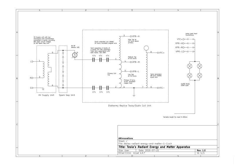
2. Spark gap generator, (static or rotary), driving directly a primary matching and tuning circuit, (tuning circuit as shown in Fig. 1.4 below).

3. Spark gaps driving a modern replica of an H.G. Fischer diathermy generator.

4. An original 1920’s H.G. Fischer diathermy generator.

Experiments in single wire currents investigate the interesting and unusual properties that result from high voltage and often high frequency waves emitted from a suitable source or generator and guided by a single wire to a load. The single wire nature means that power is passed from the generator to the load, and where the load is able to utilise this power to do work, through only a single wire. In a standard electric circuit a source of electric power such as a battery or an oscillator would be connected from both the +ve and -ve terminals for a current (dc or ac) to move around the circuit, and doing work in the circuit dependent on the characteristics and nature of the circuit. In this case if one of the terminals were removed, the circuit would be considered open-circuit, no current would flow, and no power could be utilised to do work within the circuit. In the single wire case the power conveyed through the electric and magnetic fields of induction easily do measurable work e.g. lighting an incandescent bulb, whilst the current in the circuit appears to be guided only by a single wire, that is, there is no obvious return wire for the current to pass back to the generator and create the required “circuit” for the classical conduction of electric current.

In part 1 of this experiment a vacuum tube generator is used to apply an rf sinusoidal (ac) current to the primary of the flat coil in CW mode. By extension of the magnetic field of induction to the secondary coil a magnified electric field of induction (emf) is induced across the secondary of the coil. When the secondary coil is further connected to a load via a wire at the bottom-end, or outer-end, an oscillating current (resulting from a reciprocal inter-action between the electric and magnetic fields of induction) is guided by the conductor of the wire to the load. In conjunction a pick-up coil is used behind the secondary to induce a small part of the magnified wave and feed this back to the vacuum tube oscillator. This positive feedback signal drives the oscillator at the dominant (tuned) frequency of the flat coil, in this case the lower resonant frequency FL at ~ 1850kc/s where CP ~ 900pF. In this way the circuit can be measured at a single frequency which can be tuned and adjusted using the primary capacitance CP.

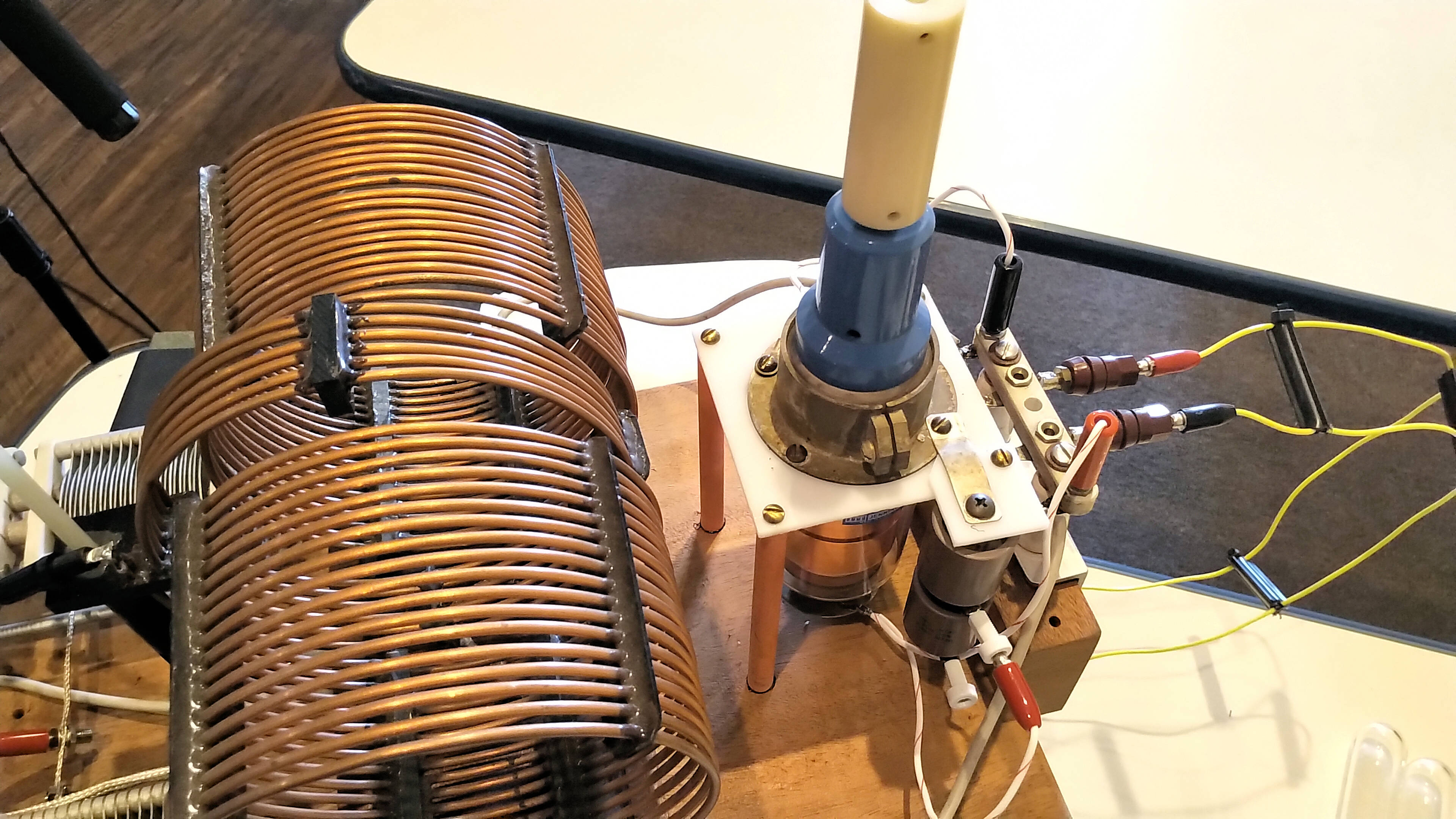
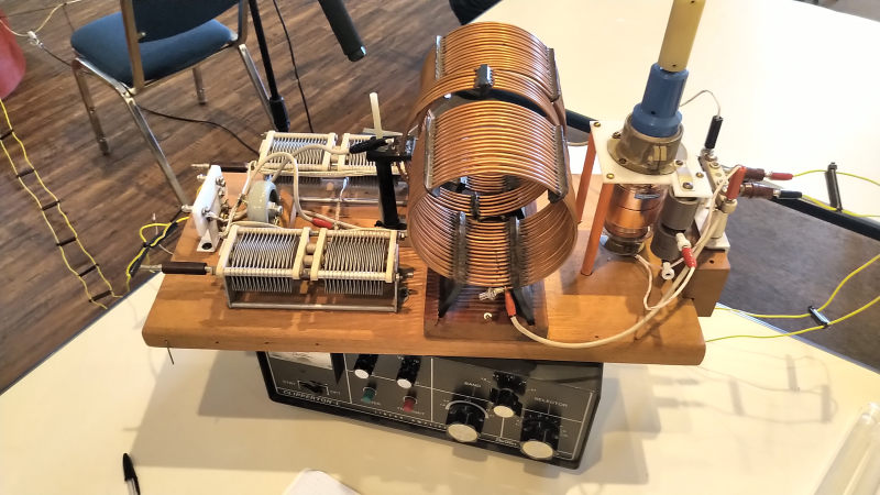
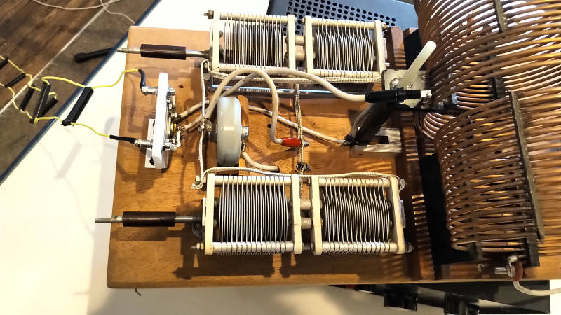
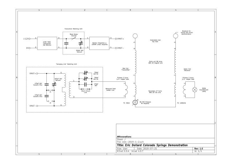
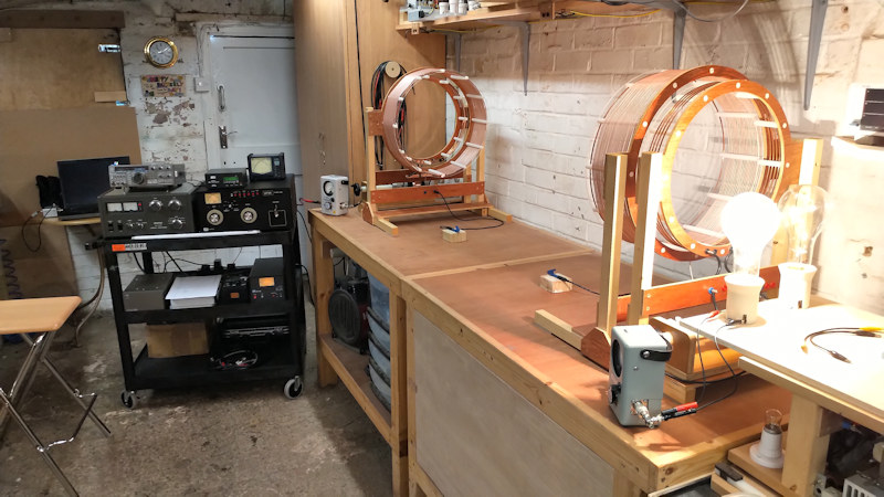
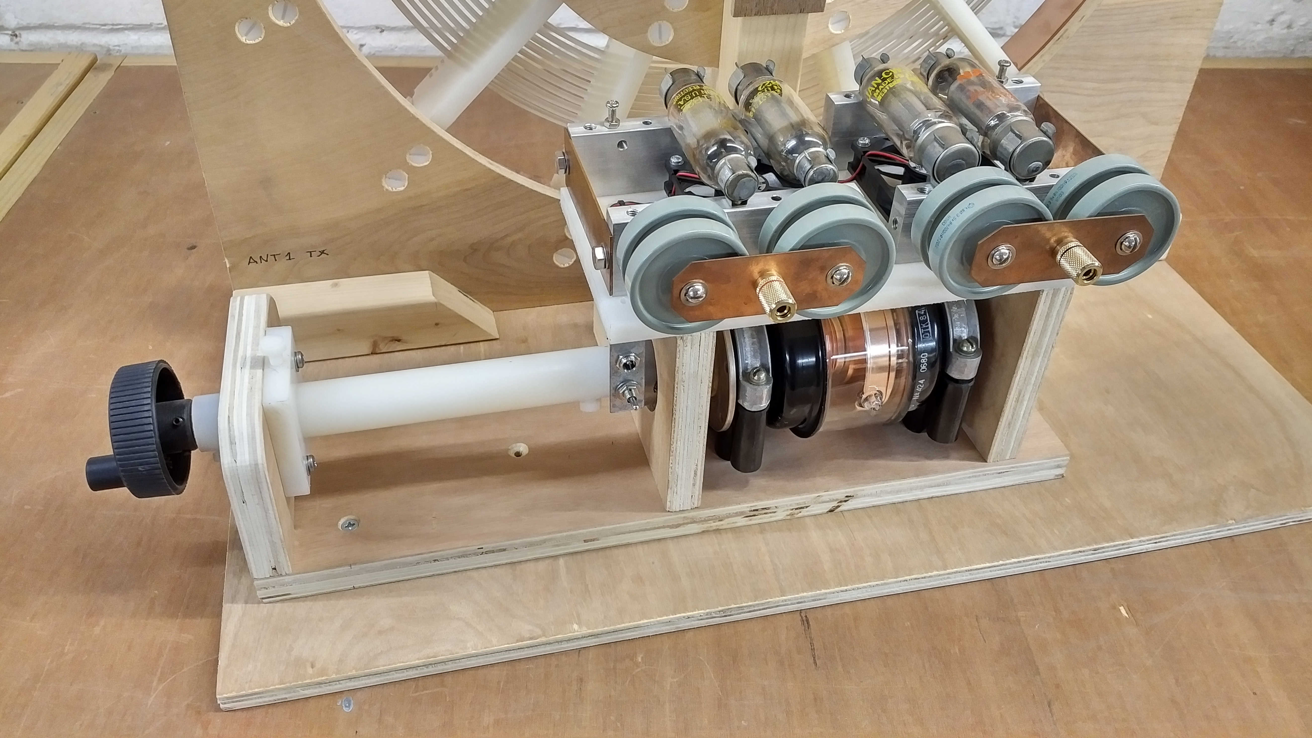
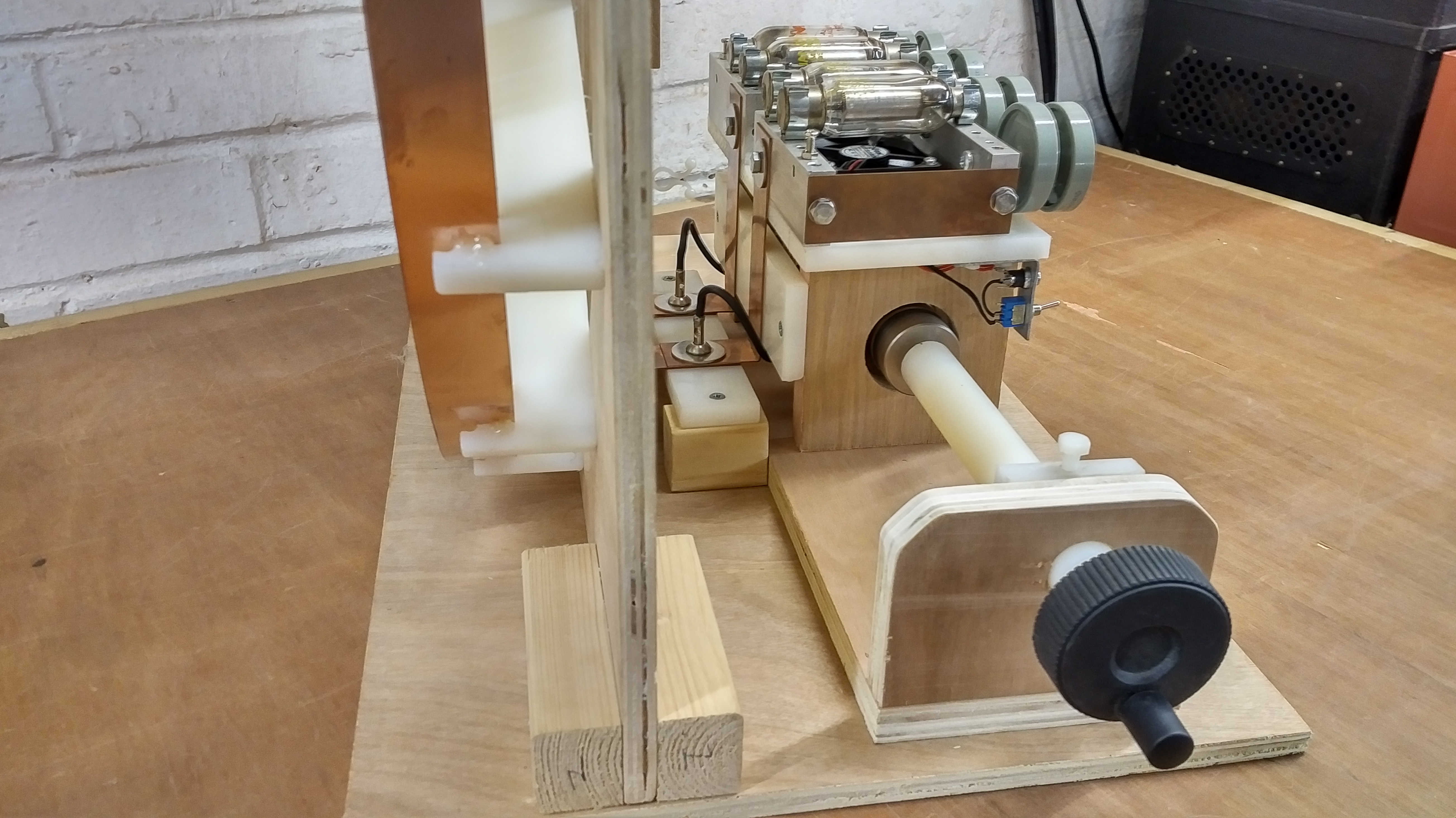
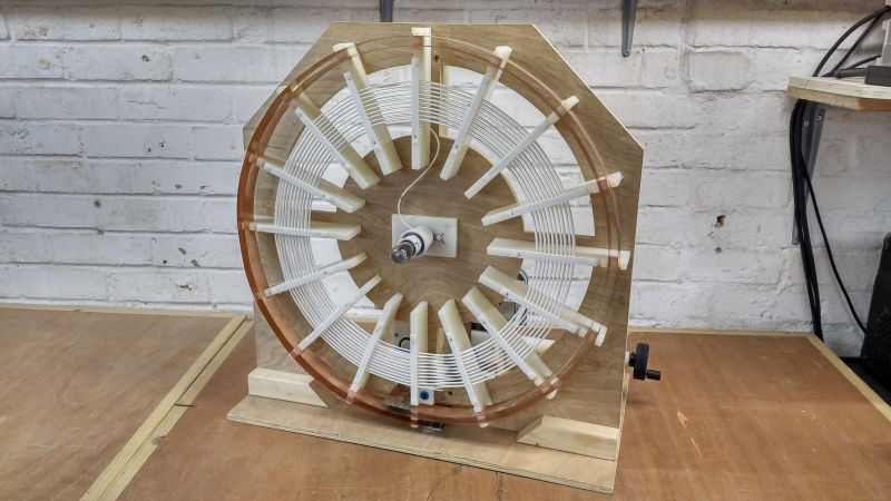
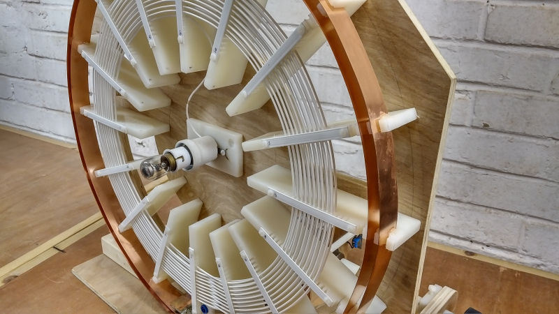
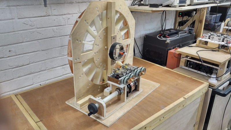
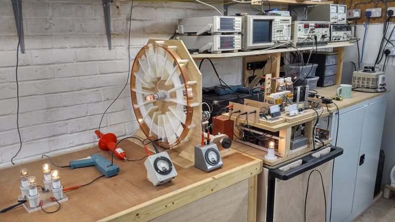
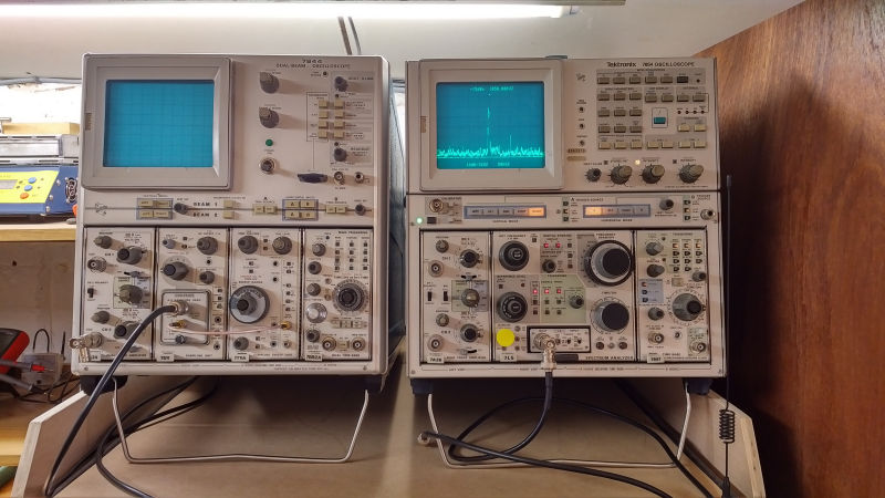
Figures 1. show the generator connected flat coil 1S-3P to be used in the single wire current experiments, and including the primary tuning circuit with primary capacitance CP, in this case a 4kV vacuum capacitor:

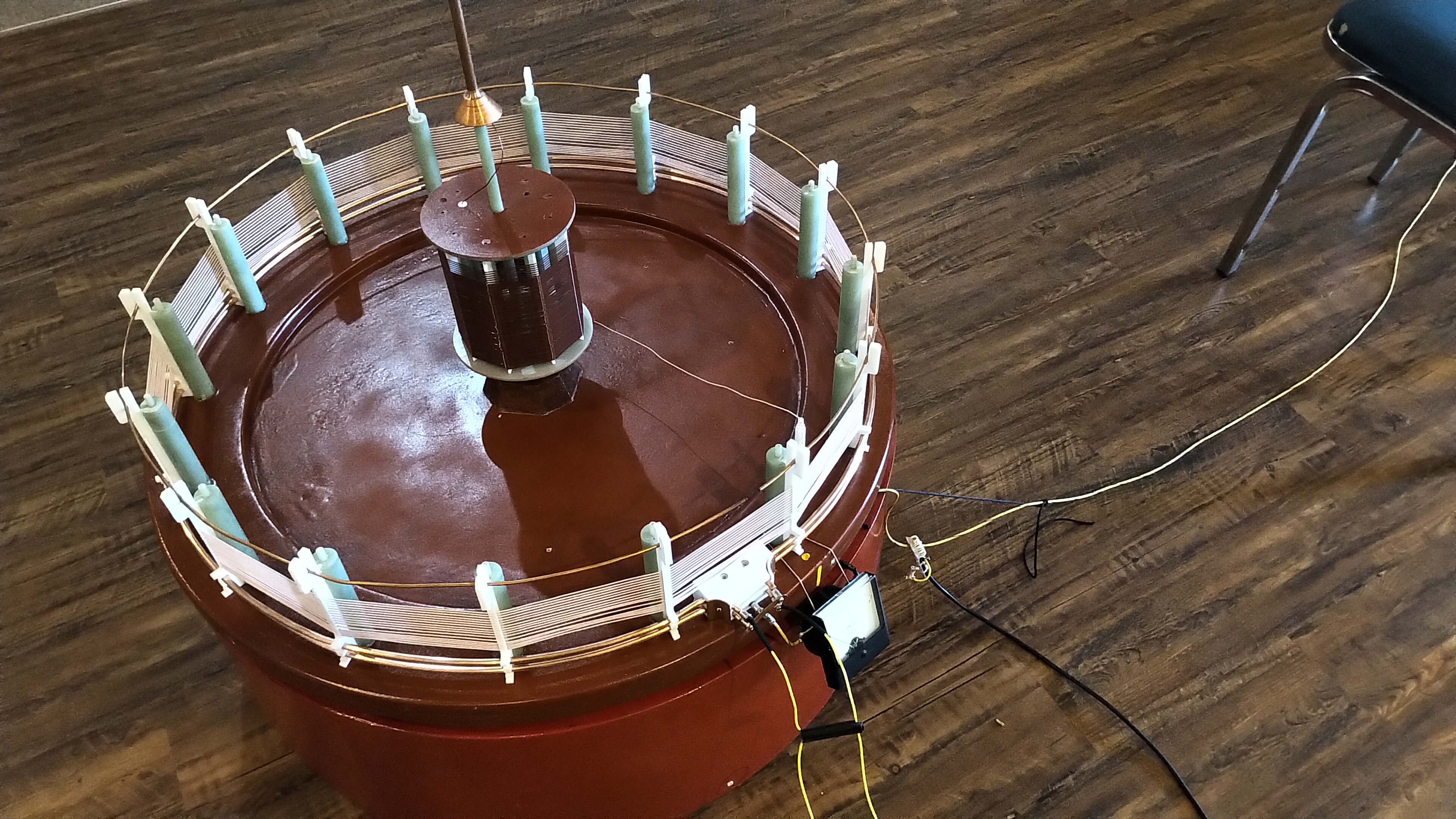
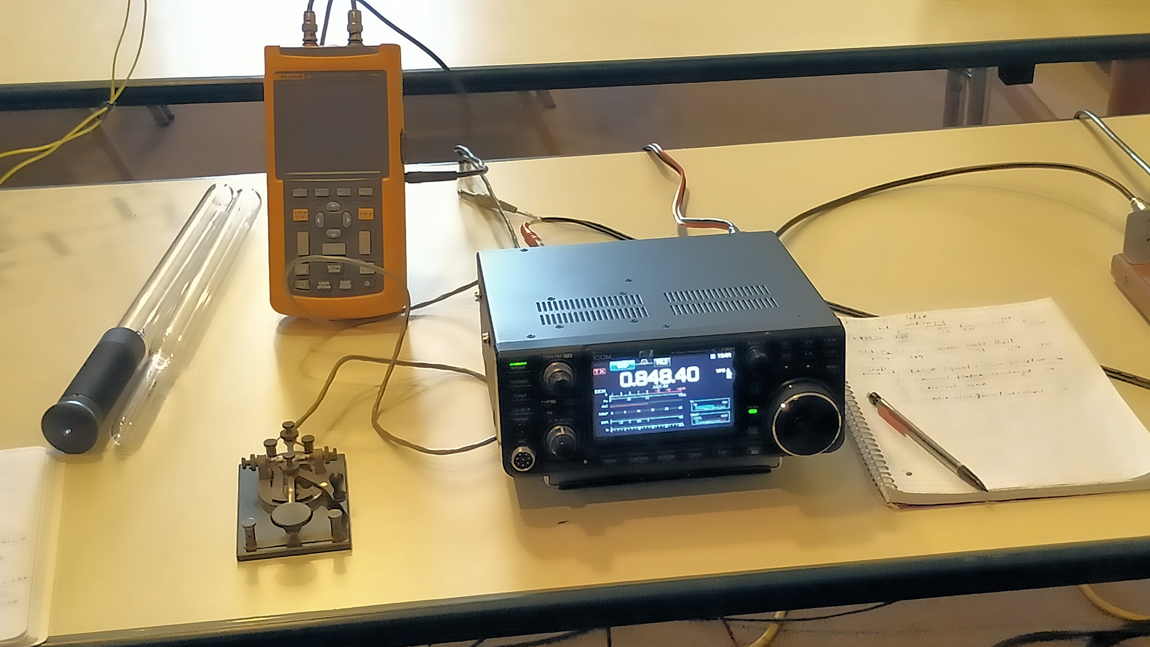
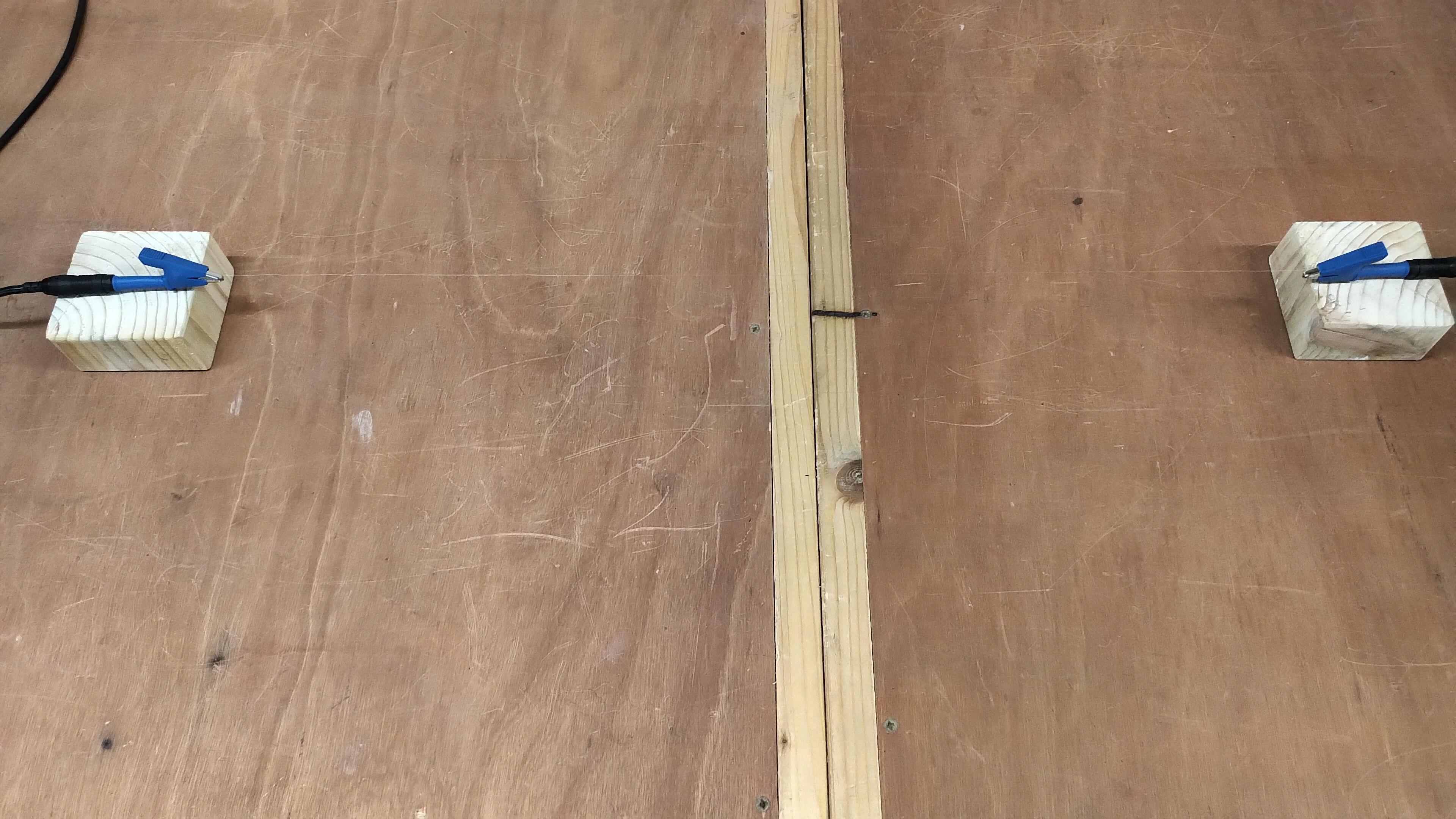
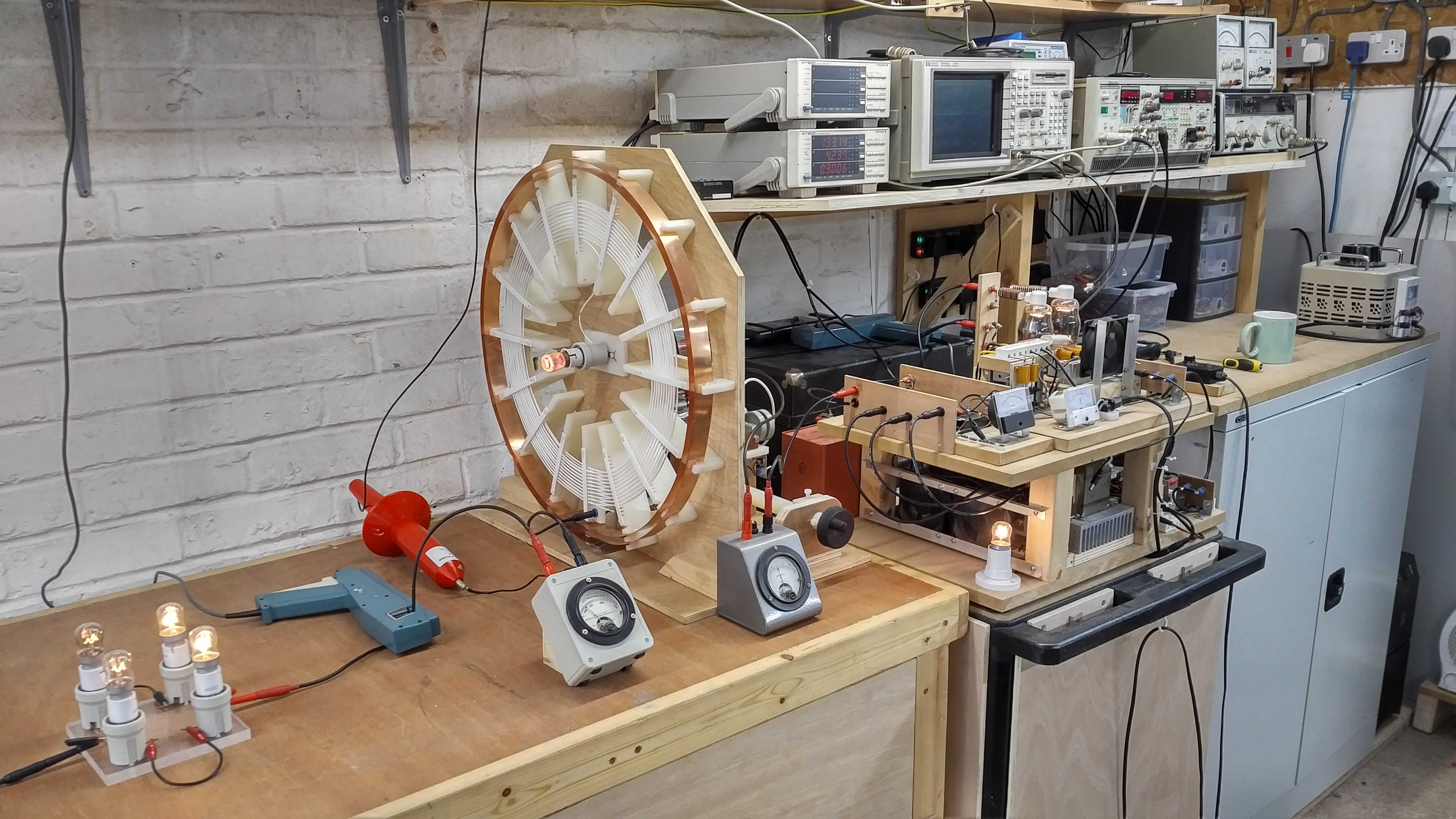
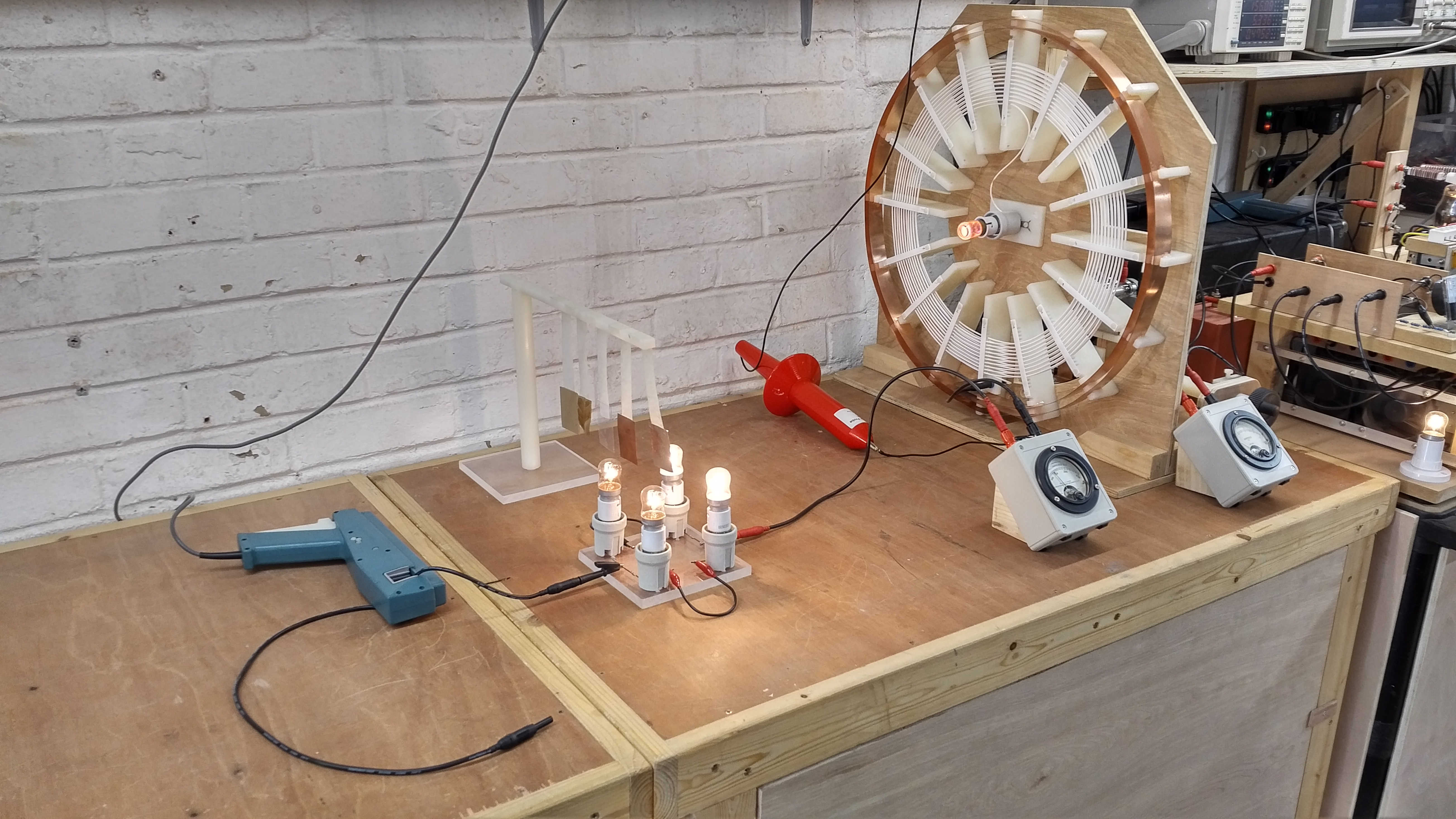
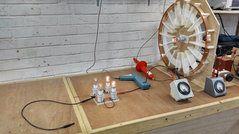
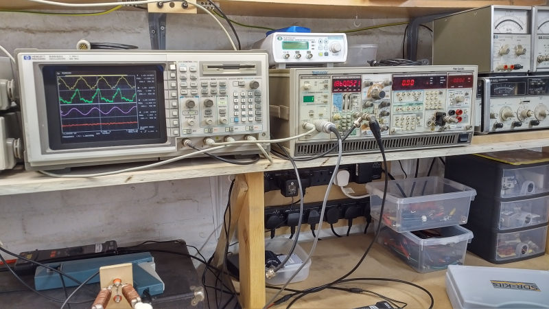
Figures 2. show the single wire current experimental apparatus, including measurement equipment and probes:

To view the large images in a new window whilst reading the explanations click on the figure numbers below:

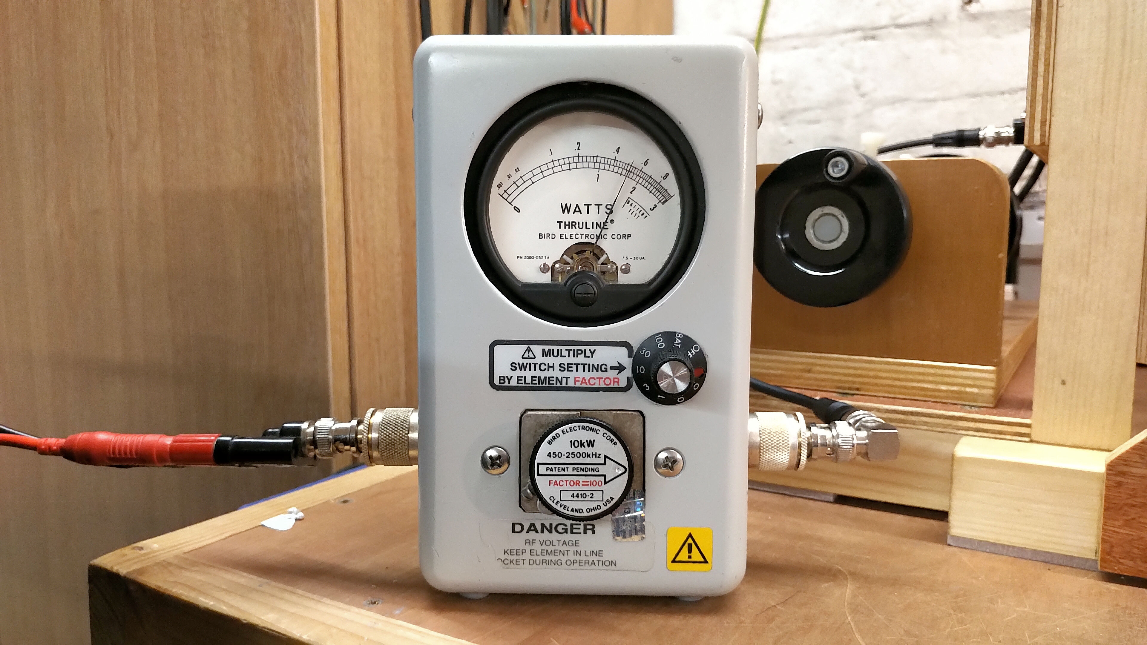
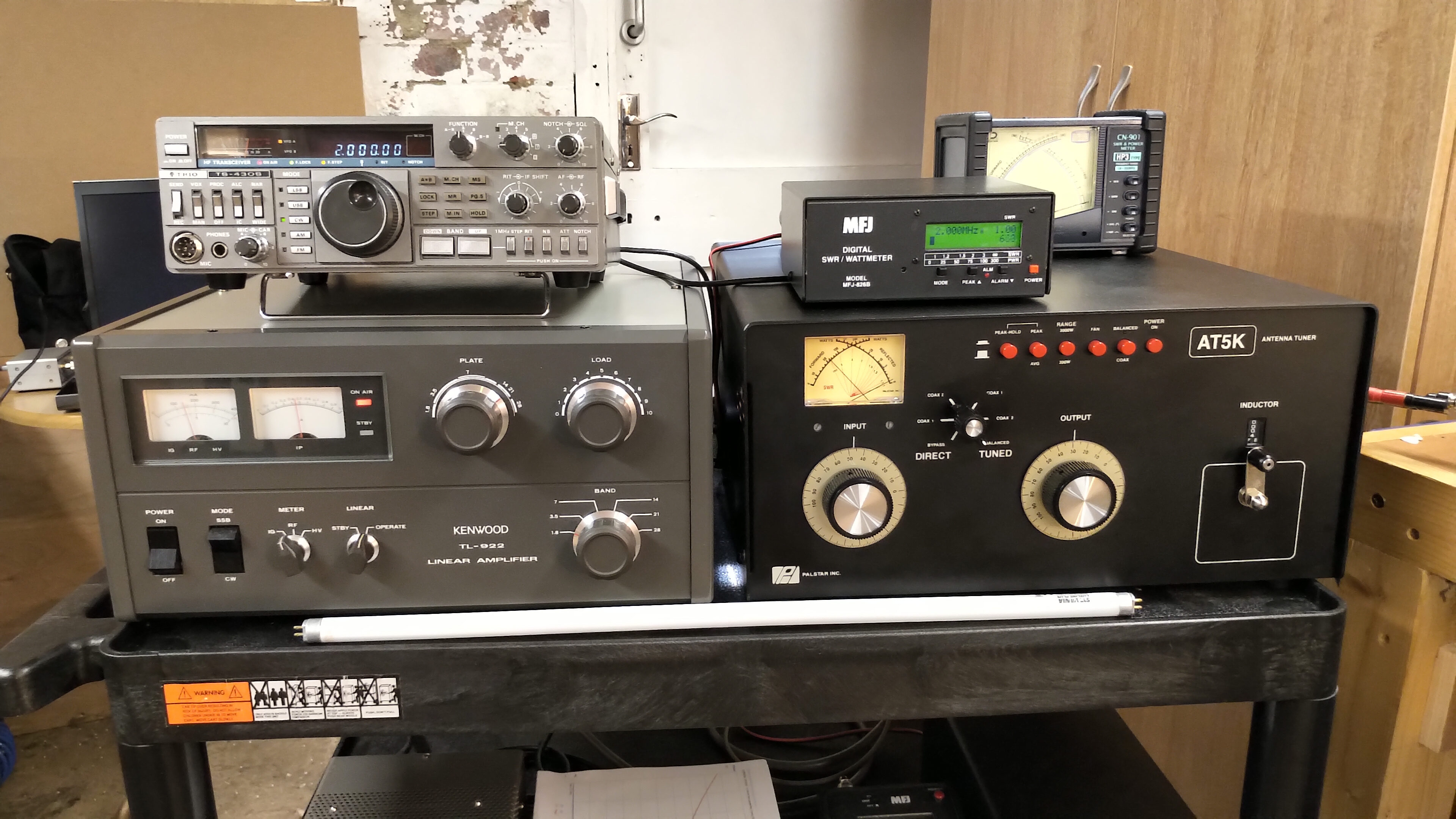
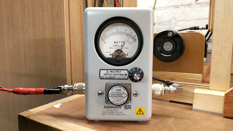
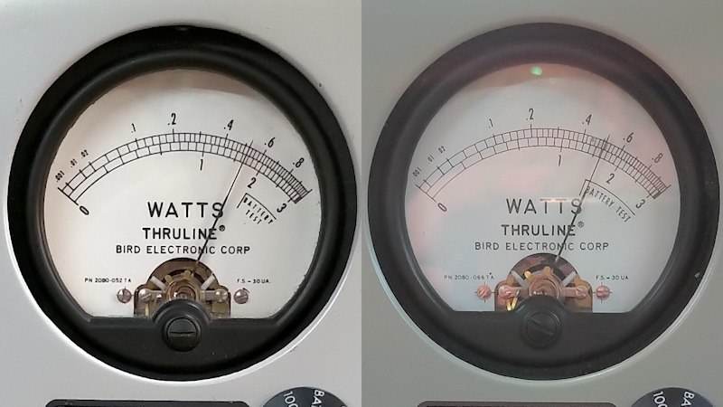
Fig 2.1. Shows the overall experimental apparatus, measurement probes, and equipment. The vacuum tube generator feeds the connections to the tuning unit with the primary capacitance. A high voltage differential probe Pintech DP-50 is connected across the primary capacitance to show the electric potential VP applied across its terminals. A current probe Tektronix A6303 is connected around the wire between the primary capacitor and the plates of the vacuum tubes to show the electric current IP moving through the primary circuit. Inserted between the high voltage tank capacitor and the input to the primary is a Weston model 425 rf ammeter (either 1A or 5A full scale deflection (fsd) dependent on generator output, and with internal thermocouple), to additionally monitor the primary rf currents IPRF.

In the secondary circuit the top-end of the flat coil is terminated with a 240V 5W (UK standard) neon bulb to act as an indicator of the magnitude of induced electric potential or tension, and to contain the top-end with a defined impedance. This containment assists in stabilising the resonant cavity formed by the secondary coil, and without significantly loading the coil and effecting the upper and lower resonant frequencies, or the Q-factor. The bottom-end of the secondary coil is connected by short wire to another Weston model 425 rf ammeter (250mA fsd) combined with a parallel 5Ω shunt to make 500mA fsd and to monitor the secondary rf currents ISRF.

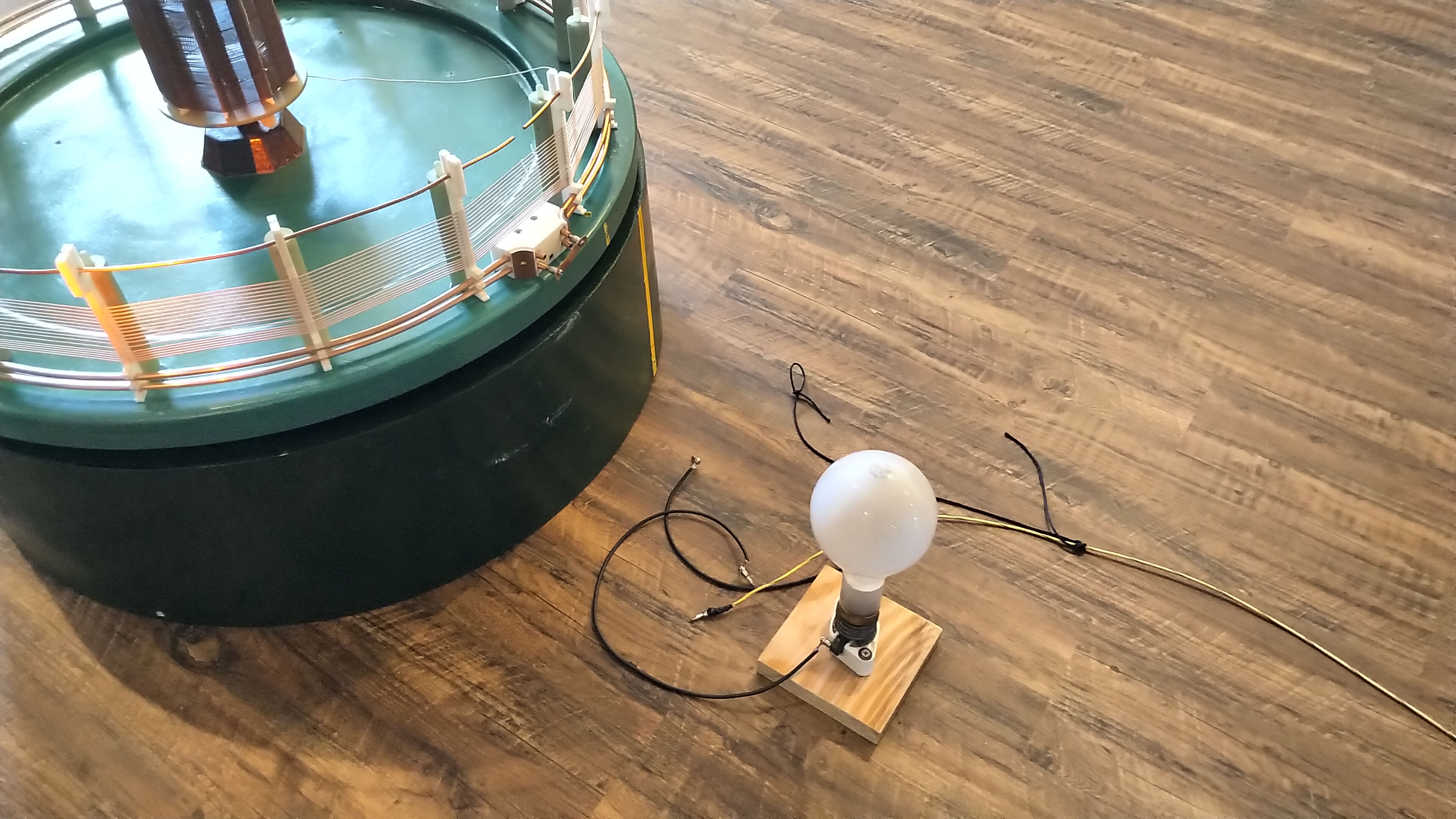
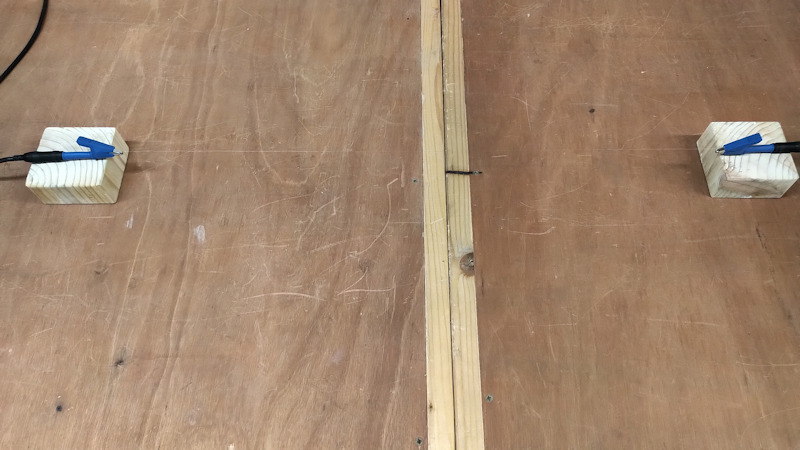
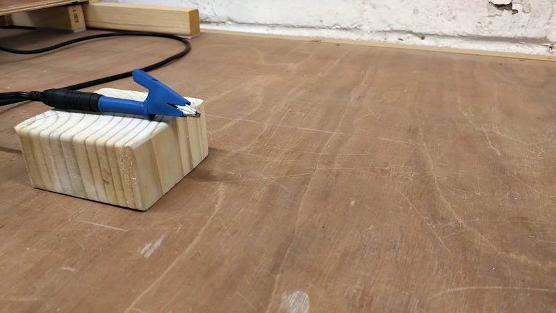
The bottom-end of the coil is also connected to a high-voltage probe Pintech HVP40 40kV 1000:1 passive probe to monitor the secondary potential VS at the lower terminal. The output of the secondary ammeter is connected to the load, which in this case is 4 x 240V 25W (UK standard) pygmy bulbs with vertically laced filaments. The bulbs can be connected in a variety of arrangements, but were here used in a two parallel twin series connected arrangement so that all 4 bulbs will light as the load. The output of the load was connected to an 80cm flying lead. Secondary current IS was monitored in various places using a second Tektronix A6303 current probe.

The outputs of probes VP and IP from the primary, and VS and IS from the secondary, were passed to the inputs a four input oscilloscope HP54542C for measurement and comparison. In addition the signal VP was fed to a Tektronix DC5009 Universal Counter to confirm the oscillation frequency of the primary circuit. This frequency of oscillation was also monitored via a Tektronix 7L5 spectrum analyser fed by a small whip antenna at the input. Throughout the experiment the Tektronix current probes 2 x A6303 connected to AM503B current probe amplifiers were set on 1A AC /division. The total input power to generator PIN, (input to the high voltage transformers only), was monitored using a Yokogawa WT200 digital power meter.

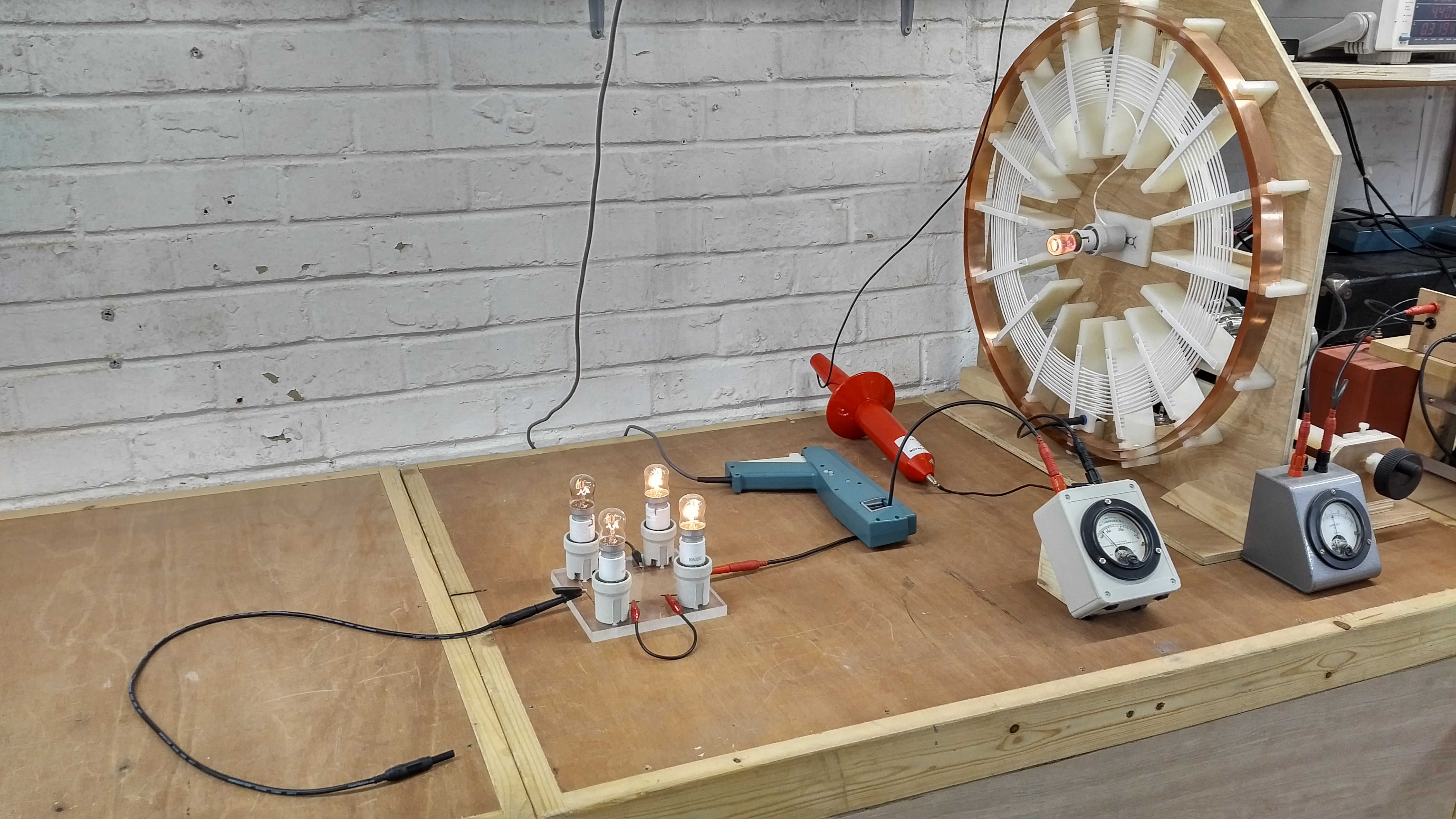
Fig 2.2. Shows that at an input power of PIN = 319W @ 1851kc/s, IPRF ~ 700mA, ISRF ~ 240mA (2 x 120), and a 80cm fly lead connected to the output of the load bulbs, that all the bulbs are lit with the first two bulbs being lit brightly whilst the second two bulbs are only dimly lit. The measured waveforms will be considered in more detail in Figures 3.

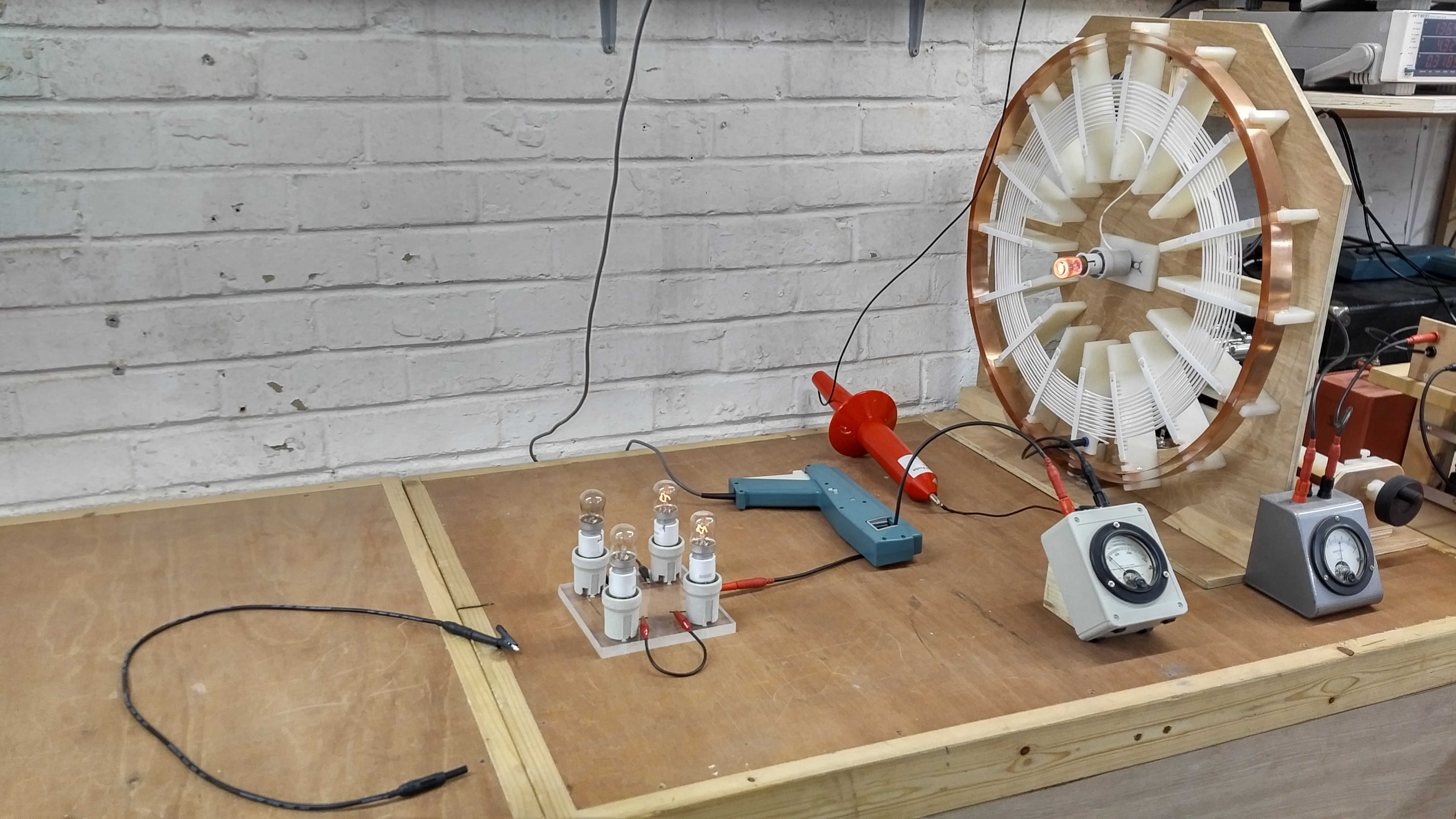
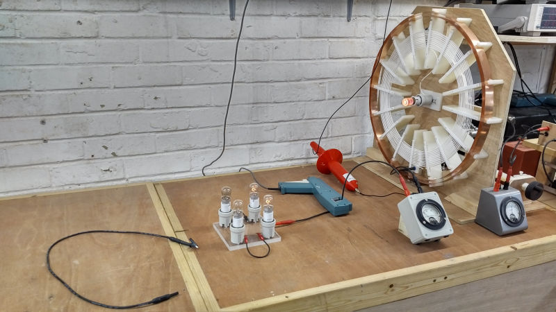
Fig 2.3. Shows that under the same electrical conditions with the fly lead removed from the second load bulbs the intensity of the bulbs is greatly reduced. The first set of load bulbs are now dimly lit, whereas the second set of load bulbs are not visibly illuminated. ISRF has also reduced considerably to ~ 100mA (2 x 50mA), whilst IPRF  increased slightly to ~ 770mA, at a PIN = 318W @ 1860kc/s. Here the frequency of oscillation has increased slightly due to the reduction in wire length with the fly lead removed, although vacuum tube generator has compensated automatically to shift resonance to the new resonant frequency via the secondary pick-up coil. The most important feature here is that in single wire current experiments loads will not power when no fly lead or terminating lead is connected to their output. In the case of a bulb it will not light when it is the last device connected to the single wire.

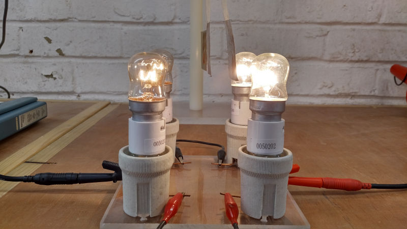
Fig 2.4. Shows the effect of introducing a conductive material close to the load in this case an aluminium leaf suspended by masking tape from an insulated support. Within a certain distance the aluminium leaf is attracted to the bulb outer glass surface and can remain held in this place until the generator is turned off. It appears a force is applied to the aluminium leaf that will move and/or retain the leaf in a distance offset from the vertical. This unusual result has been investigated in a variety of different ways and will be introduced here, to be further investigated and described in subsequent parts.

In the case of the CW vacuum tube generator (VTG-CW) the waveform induced in the secondary circuit is a steady and constant oscillation at a single frequency. This is a very linear and determinate condition and has been found to have the least intensity on the phenomena of attraction of conductive materials. At input powers typically 250W upwards in the experimental apparatus shown the aluminium leaf is very slightly attracted to the bulb glass. If placed only 1mm from the surface then the leaf will be pulled directly from vertical to a point on the glass bulb surface and held there. For distances x between the leaf and the bulb in the range 1mm < x < 15mm, and for the VTG in CW mode, the leaf can be held in place when initially placed on the bulb surface. Above ~15mm the aluminium leaf will not be retained on the bulb surface but will swing back to the vertical position.

The magnitude of the force applied to the aluminium leaf increases with the input power PIN to the generator and hence ISRF in the secondary wire. The overall effect is similar to observing a magnetic metal attracted to a magnet at close range, or the effect of electrostatic attraction in the case of opposite charged metal plates spaced slightly apart. In this case however it appears that the effect is based on the electric field of induction being dominant in the scenario rather than magnetic field of induction. When a permanent magnet is introduced into the experiment it has no influence on the attraction of the aluminium leaf either in being attracted towards the bulb, away from it, or being held on the bulb surface.

The intensity of the attraction and hence the magnitude of the applied force on the leaf has been found to increase significantly with burst, impulse, and modulated waveforms. With a burst or impulse waveform from the generator it is easily seen that at PIN > 400W the leaf can be instantly attracted to the bulb and move from the vertical over distances as much as 20mm, and then held there strongly on the surface of the glass.  in this case even with the generator turned off the leaf can be retained for up to 60 seconds on the surface of the bulb before being released and swinging back to the horizontal.

Other types of leaf material have also been tested, and those found to readily be attracted and retained to the bulb glass have a conductive element to them, including metals like aluminium and copper, organic materials such as living tissue, plant matter (e.g. leaves), and paper, cardboard, and woods with a certain content of moisture in them. In the case of organic living tissue the presence of my hand in the vicinity of the light bulb, but not touching, greatly increases the effect even in CW mode. For man-made synthetic materials such as plastic and other insulating mediums there is normally no discernible attraction towards the bulb. At very high voltages and high input powers PIN > 1000W a plastic leaf was found to attracted to the bulb surface over a tiny distance < 0.5mm but could not be retained on the surface of the bulb even when placed directly on the surface.

With the aluminium leaf the voltage on the leaf was measured during the process of attraction and was found to rise to a high dc potential usually in the order of several hundred volts in the experiment thus described. This indicates a form of “charging” like the plate of a capacitor when exposed to a dc potential higher or lower than the surrounding environment. In this case the electric field of induction appears to have created a region of potential difference and tension between the material of the leaf, where the leaf has become “charged” to an opposite polarity than that present on the glass surface of the bulb. It is conjectured here that an electric wavefront (a positive dc level or impulse rather than a varying sinusoid) is emitted from the exposed wire of the bulb filament (itself a tiny extra coil and leading to an imbalance between the magnetic and electric fields of induction). These continuous wavefronts result in charge accumulation on the surface of the conductive material which establishes an electric field between the bulb filament and the conductive material. The electric field results in a force exerted on the aluminium leaf which is pulled towards the glass surface. As the conductors of the filament and the leaf are prevented to come into contact by the glass bulb the electric field is not collapsed by shorting the two together, and the leaf can be retained firmly on the glass surface as it remains “charged” by the presented wavefronts.

It is suggested that the attraction is not likely to be magnetic in nature, and as a result of eddy currents in the conductive material induced by the presence of a time varying magnetic field, as the phenomena cannot be influenced by other magnetic fields in very close vicinity, such as permanent magnets and electromagnets. It would be expected that the magnetic field generated by eddy currents in the leaf would be disturbed by the introduction of a strong permanent magnet, however no such disturbances have been observed or measured.

To eliminate effects due to convection and movement of air due to heating of the glass bulb a control experiment connected the same bulb type, a 240V 25W pygmy bulb, to a normal domestic ac outlet so that it would light to normal intensity and heating. The aluminium leaf was then placed in very close proximity to the bulb surface ~ 0.5mm with no discernible movement towards the bulb over any length of time the control experiment was conducted.

Fig 2.5. Shows in close-up detail the attraction of an aluminium leaf to the surface of the load bulb and being retained on the surface until the generator is turned off. In this case with the VTG in CW mode the attraction is not strong enough to pull the leaf from the vertical over a distance of 15mm to the bulb surface. The applied force is however strong enough to retain the leaf on the surface of the bulb at a distance of 15mm from the vertical, and once placed on the surface of the bulb.

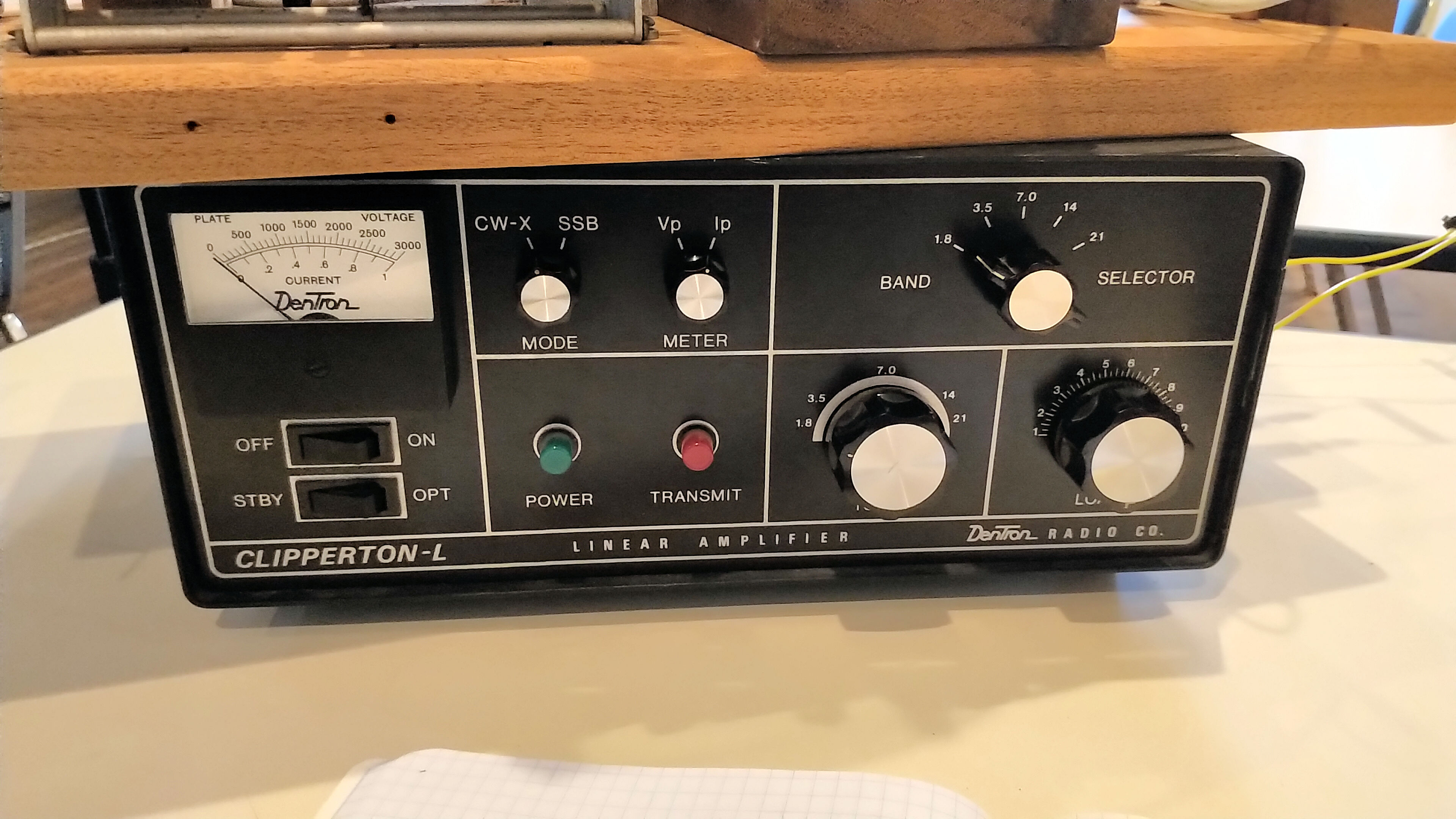
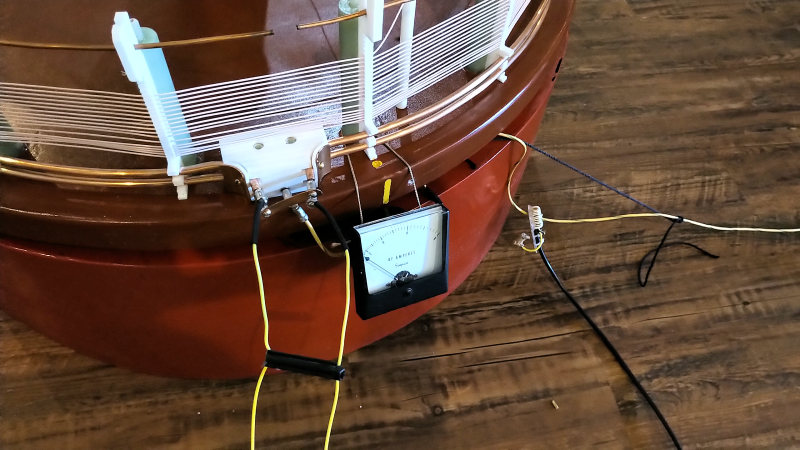
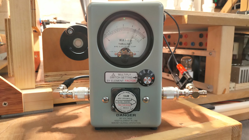
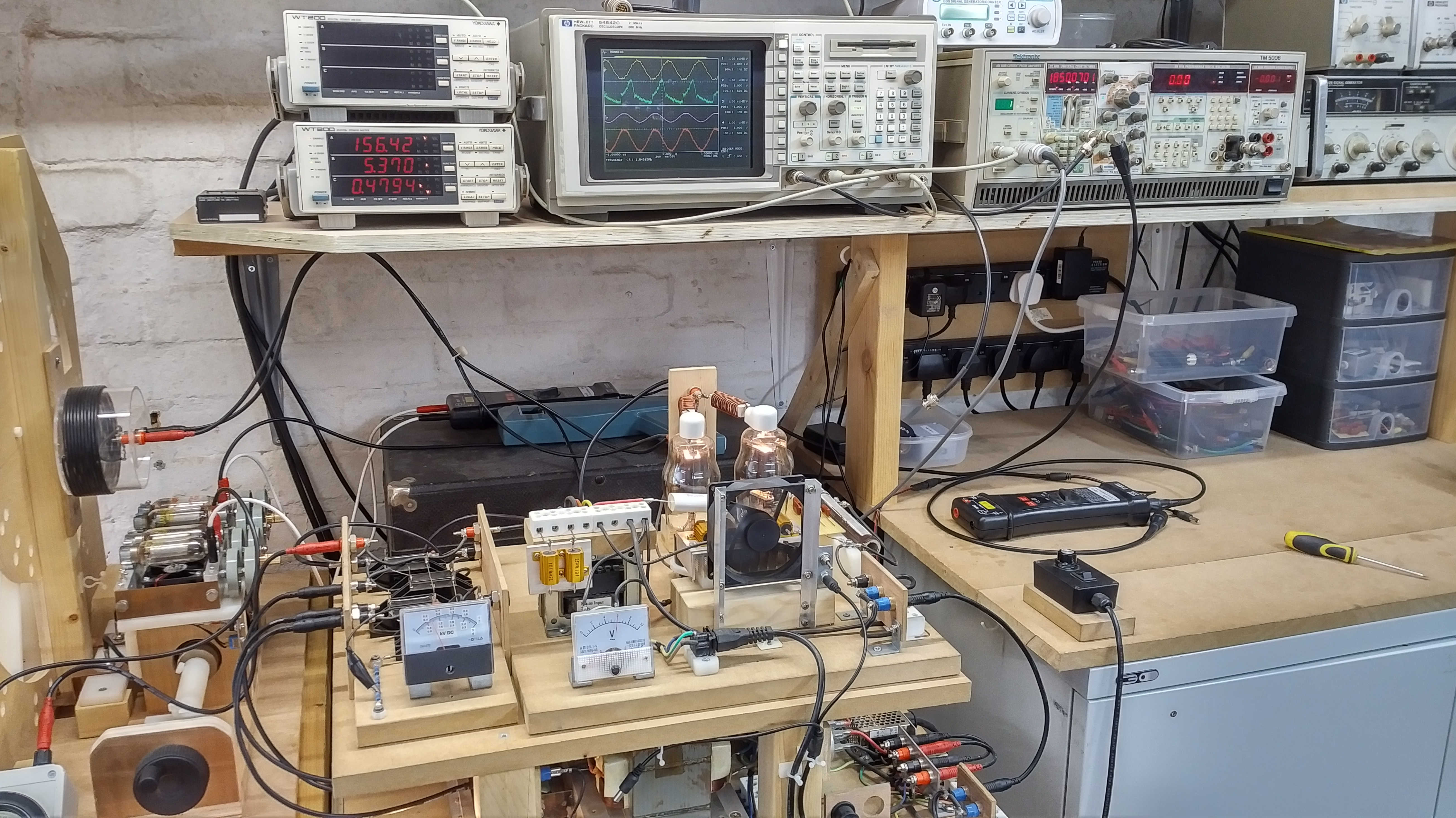
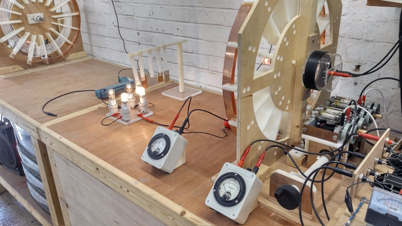
Fig 2.6. Shows the experimental apparatus from the reverse side with the generator attached to the tuning unit, the rf ammeters in the primary and secondary, and the generator tank capacitor meter in the far bottom right showing a tank voltage of ~ 800V dc.

Fig 2.7. Shows the vacuum tube generator, primary measurement probes in the background, and the test equipment setup with PIN = 479W, the primary and secondary voltages and currents measured on the oscilloscope, and the measured oscillation frequency of the primary FP = 1.850Mc/s on the frequency counter.

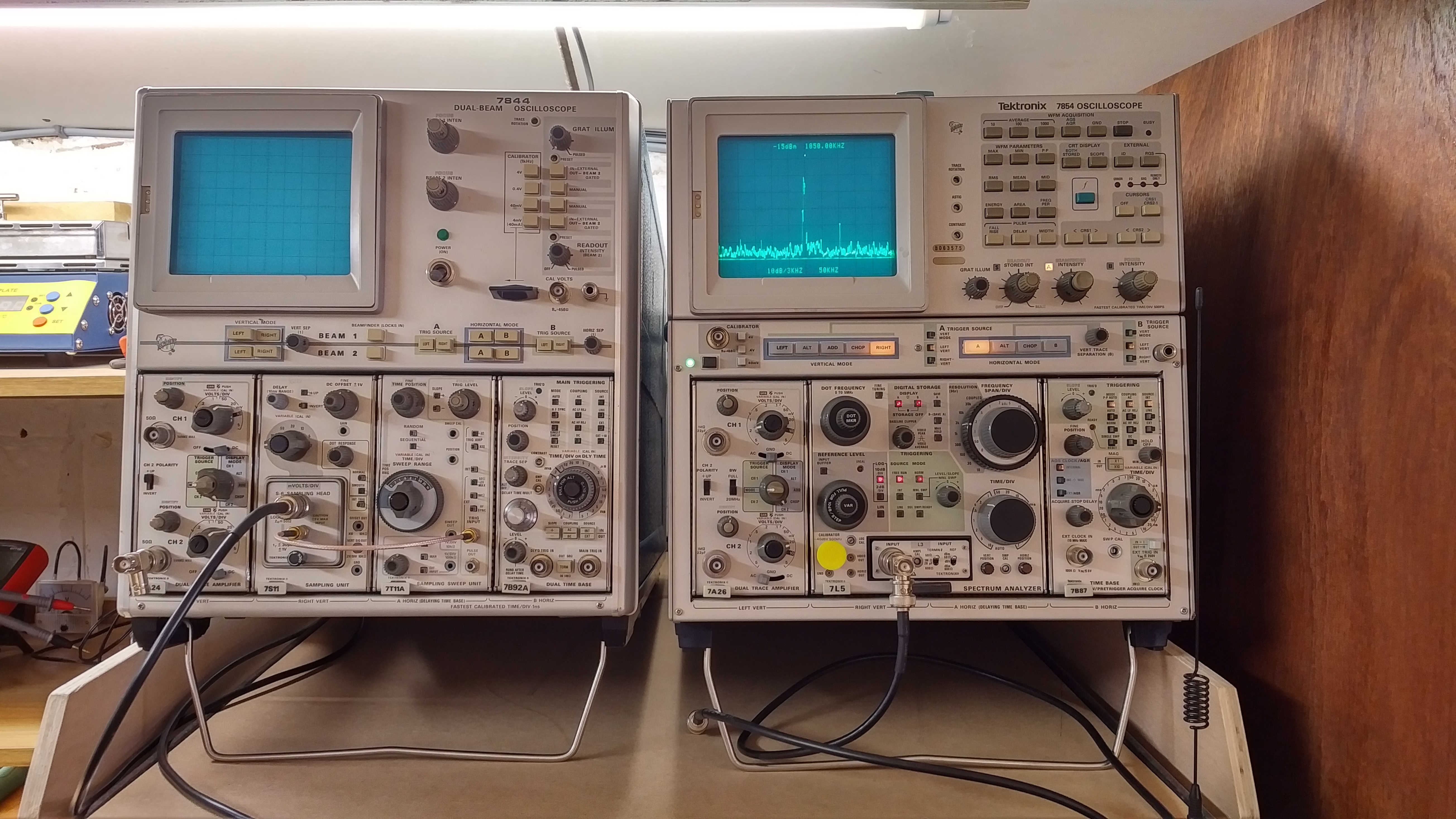
Fig 2.8. Shows the spectral response of the emitted electric field in vicinity of the experimental setup and as measured by the Tektronix 7L5 spectrum analyser connected to a small whip antenna as shown in the bottom right of the picture. The spectral response shows a significant peak at ~1850kHz, and small possibly “artefact” peak at ~1950kHz.

Fig 2.9. Shows particularly the change in oscillation frequency measured in the primary circuit when the fly lead was removed from the output of the bulb load. The oscillation frequency of the experiment changes from ~1850kc/s to ~1860kc/s.

Figures 3. show the voltage and current waveforms for the primary and secondary and their phase relationship:

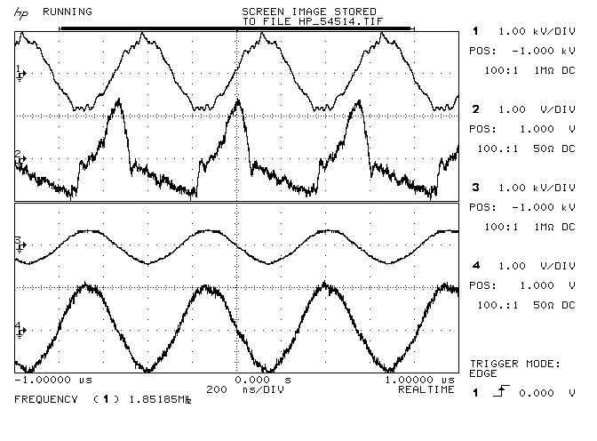
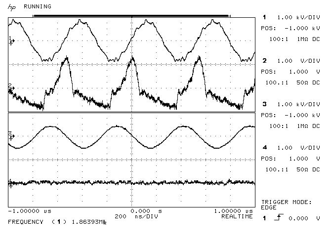
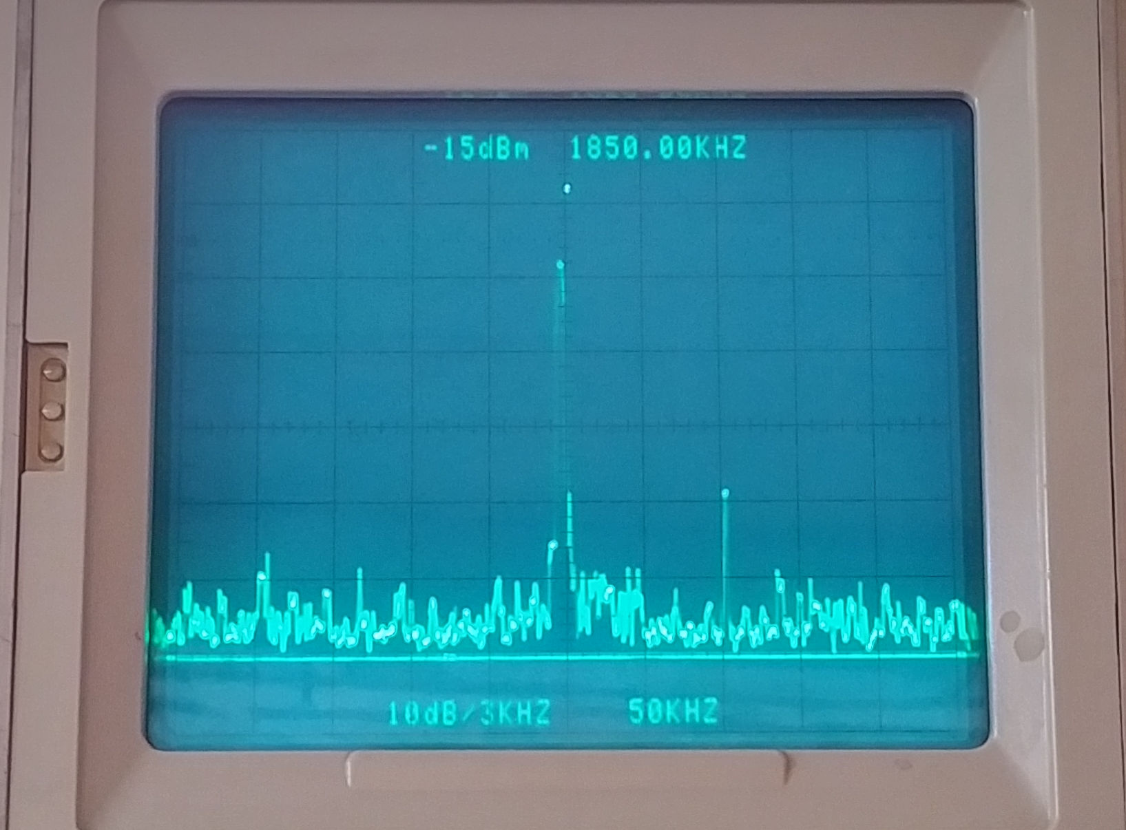
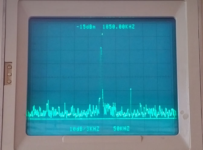
Fig 3.1. Shows the primary and secondary voltage and current measurements VP (trace 1) and IP (trace 2), and VS (trace 3) and IS (trace 4) respectively. VP is a sinusoidal oscillating voltage VPK-PK ~ 2kV. IP is more in the form of a pulsed current where the trace is calibrated 1V per amp and showing IPK-PK of ~ 2A. The phase of the current IP is leading VP by ~90° indicating that the generator appears to be driving a reactive load that is predominantly capacitive in a class-C amplifier arrangement. This is to be expected as the 180° phase change of the primary has been shown to exist at a much higher frequency than the impedance maximum for the primary would indicate. Operated in this way the primary and secondary are not at resonance simultaneously, the primary circuit is oscillating with a driven ac, whilst the secondary is acting as a free resonator at its tuned resonant frequency which determines the driven frequency in the primary.

As the voltage VP rises across the primary the current IP is maximum and falls rapidly as the primary capacitor Cis charged by the tank capacitor, on which that energy is released through the inductance of the primary coil reversing the current flow and discharging CP. This yields current pulses of sufficient magnitude for the magnetic field of induction to dominate and extend to the secondary coil. The secondary coil is not tightly coupled to the primary and so can reasonably resonate freely as the generator oscillates at a frequency determined by feedback from the secondary to the generator pick-up coil.

Using the VTG in cw mode it is important to note that the secondary is constantly being excited by the primary in a linear continuous fashion. There is no charge and discharge phase in the secondary as would occur in a burst or impulse driven primary. In this case the VTG is driving the flat coil in a very linear condition where the system operates at one set frequency, and the dominant majority of energy is conveyed at the fundamental resonant frequency, with very little contribution from harmonics. In this case we would expect phenomena that arise from the imbalance between the electric and magnetic fields of induction to be minimal, which is so far confirmed by measurement of single wire phenomena including deflection of conductive materials, and dc charging of capacitive loads.

The freely resonating secondary shows VP and Iwhich are in phase in traces 3 and 4, which is to be expected for a freely resonating coil driven with a very linear continuous wave. VS at the bottom-end or outer-end of the secondary coil is ~1kVPK-PK, and the current IP measured by the current probe prior to the load (as shown in Fig. 2.2) is ~ 2APK-PK (1V per amp calibrated on the current probe amplifier).

Fig 3.2. Shows the change in waveforms when the fly lead is removed from the end of the load, and the secondary current probe is connected through the fly lead. The frequency of oscillation has increased due to the reduced wire length in the experiment to ~1860kc/s (as measured by the frequency counter and spectrum analyser, rather than the marker frequency of the oscilloscope). The primary waveforms Vand IP remain largely the same in amplitude, phase, and form. The secondary voltage VS has increased as the effective load is reduced in the secondary, and IS has gone to zero as the fly lead, from which the current is being measured, has been disconnected from the output of the load. In this case the final load bulbs were not lighted, and the first load bulbs were lit only dimly with a significant reduction in ISRF.

Fig 3.3. Confirms the electric field detected in the vicinity of the experiment throughout the measurement period, where the pick-up whip antenna is located ~ 3m from the load bulbs.

To view the large images in a new window whilst reading the explanations click on the figure numbers below:

Figures 4. show the Z11 input impedance characteristics of the experimental apparatus:

To view the large images in a new window whilst reading the explanations click on the figure numbers below:

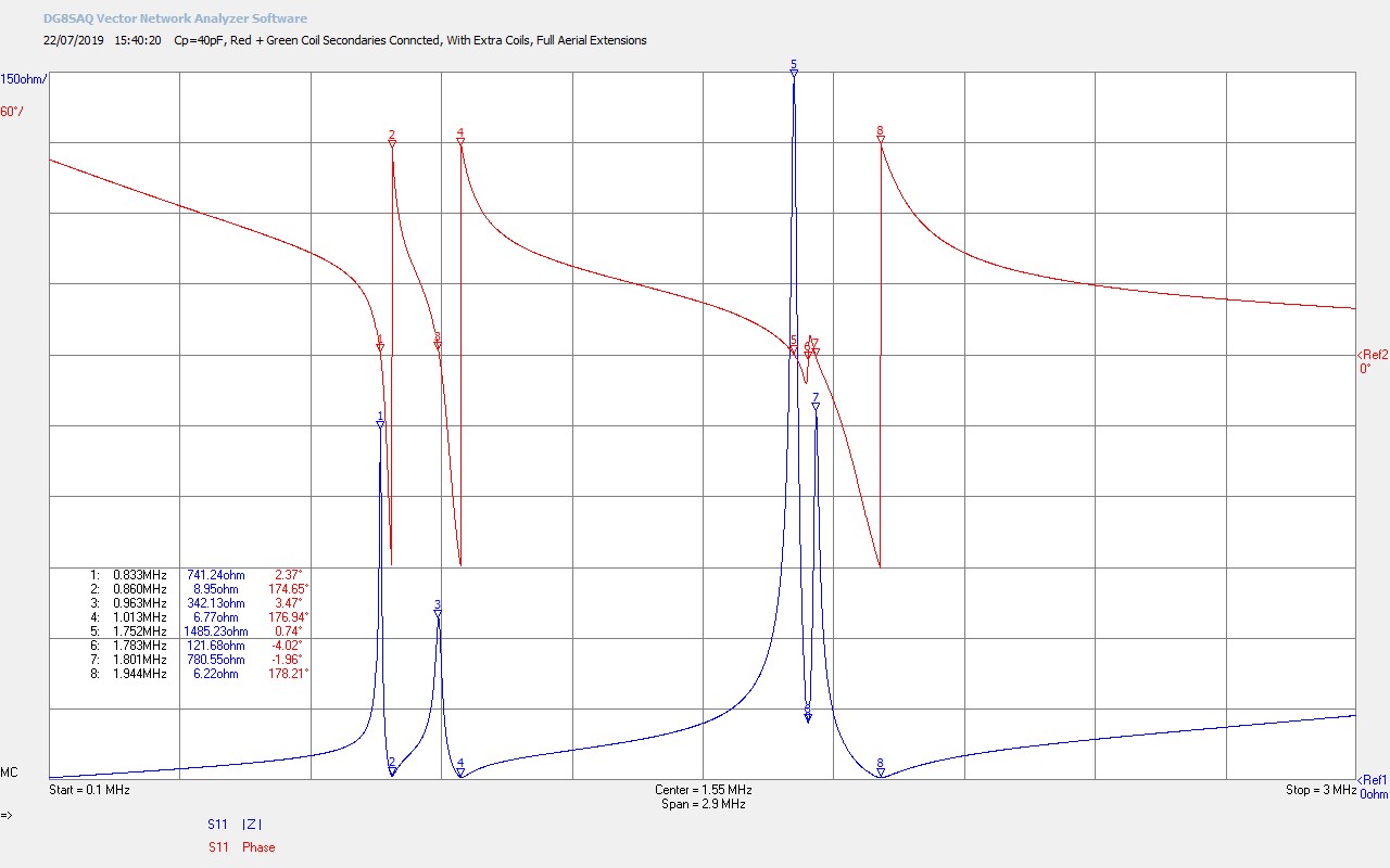
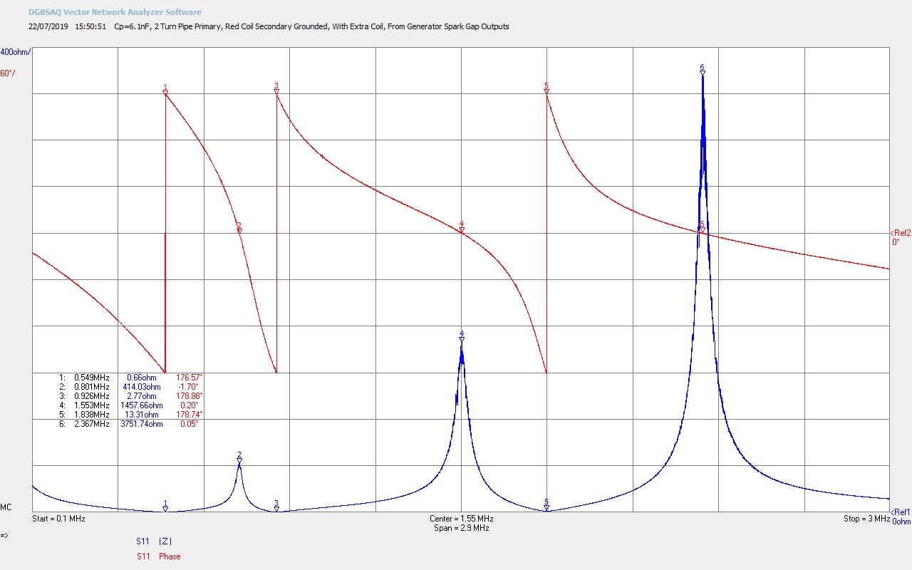
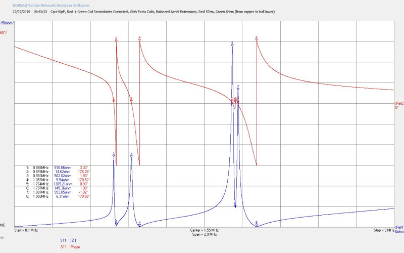
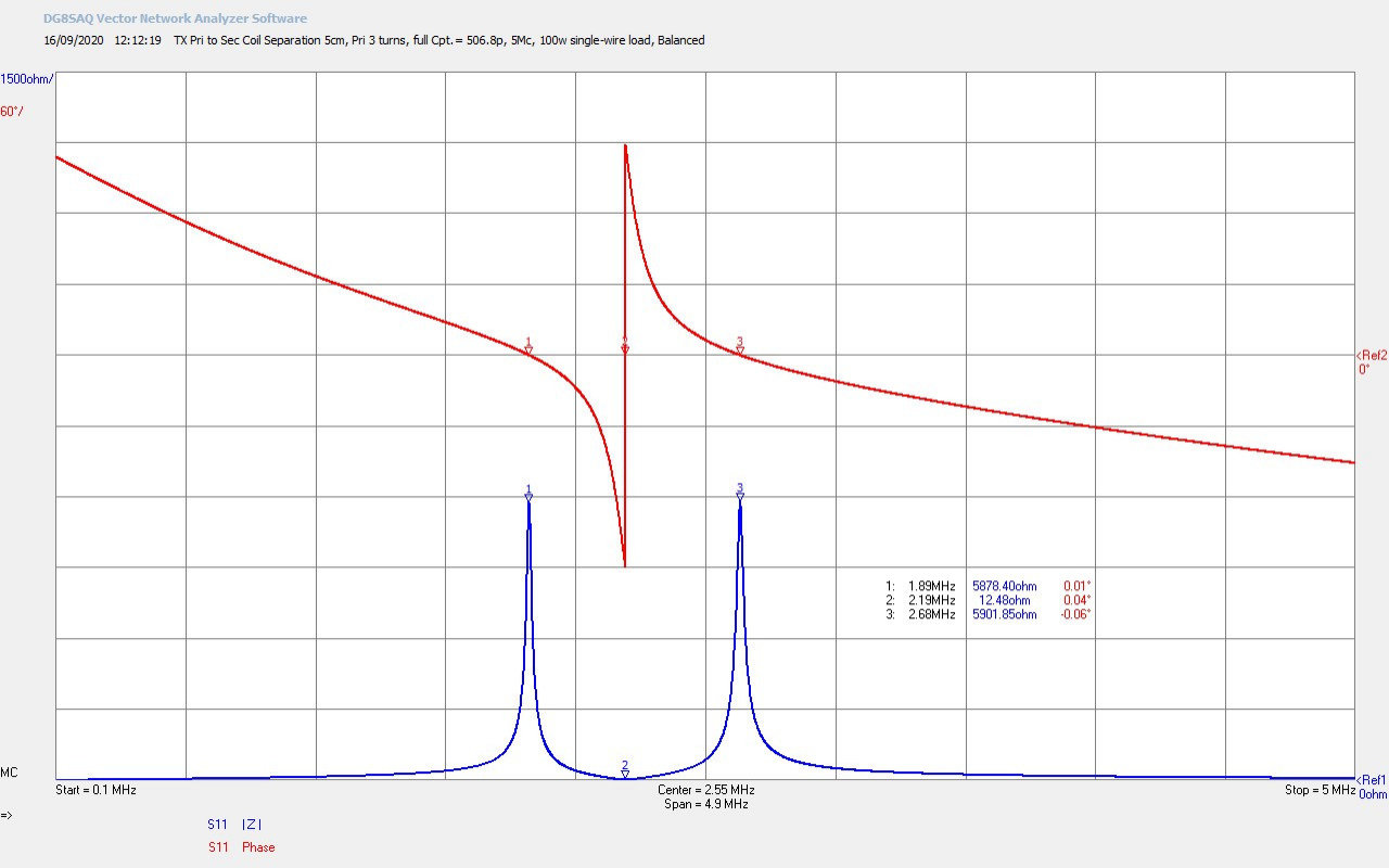
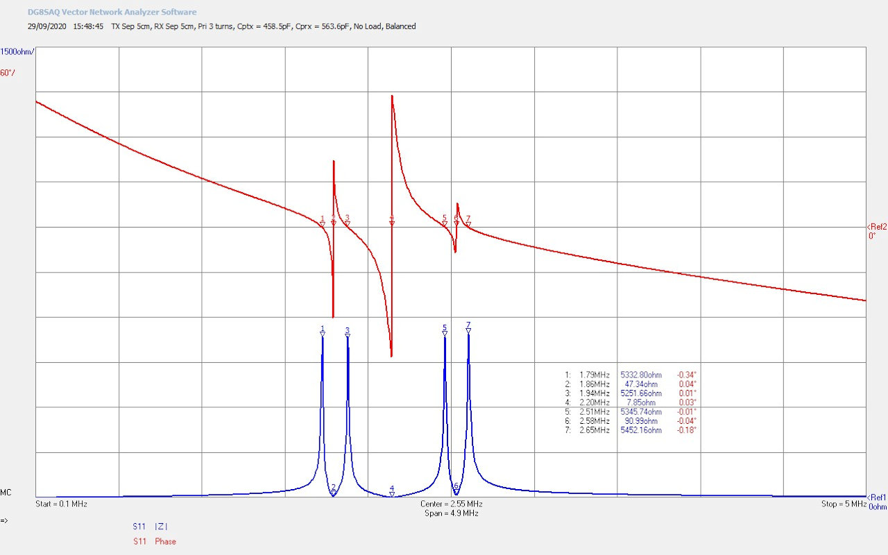
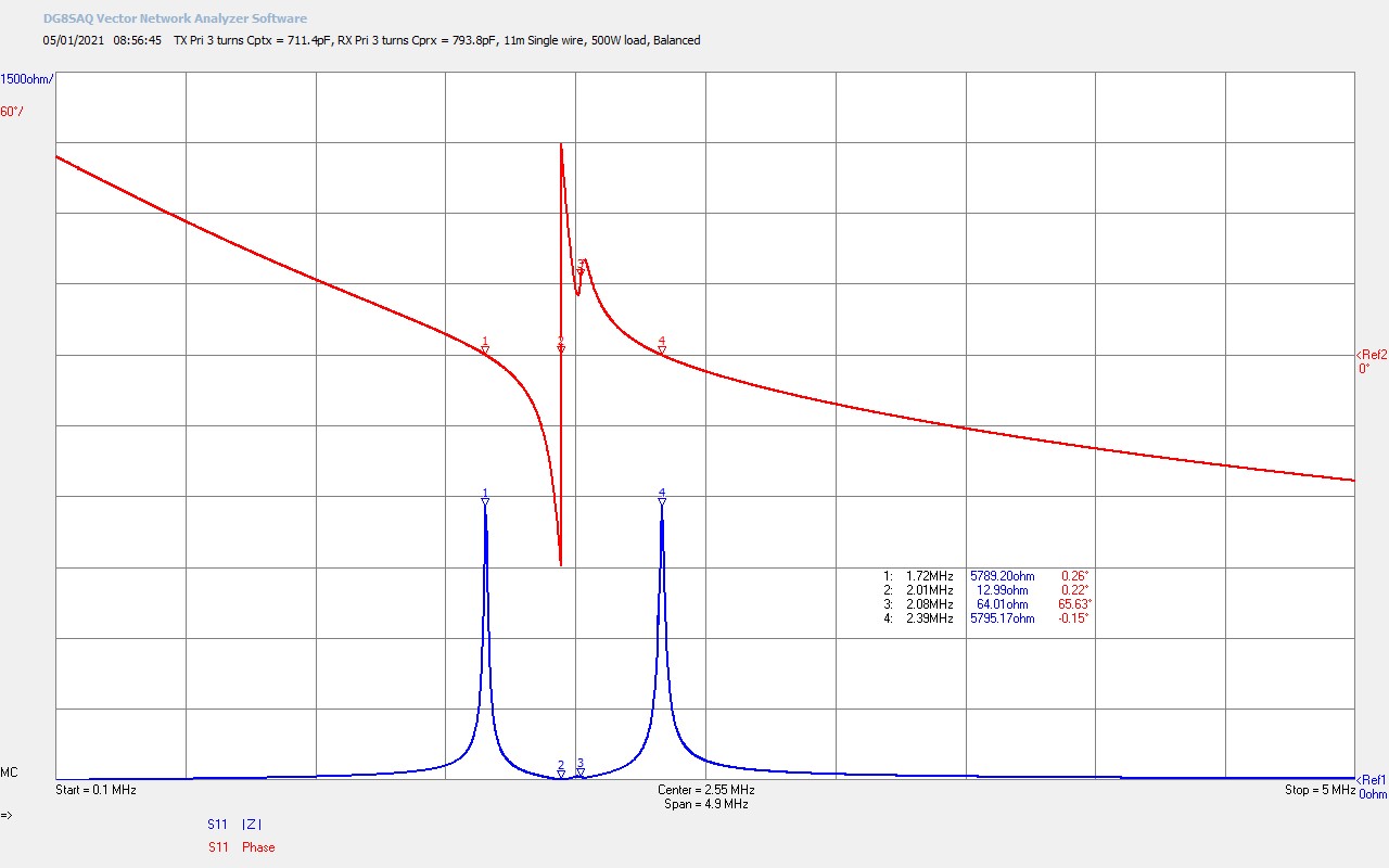
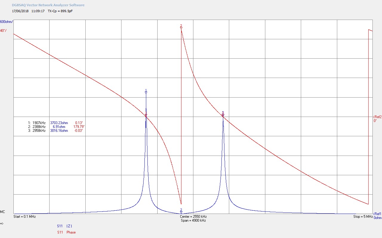
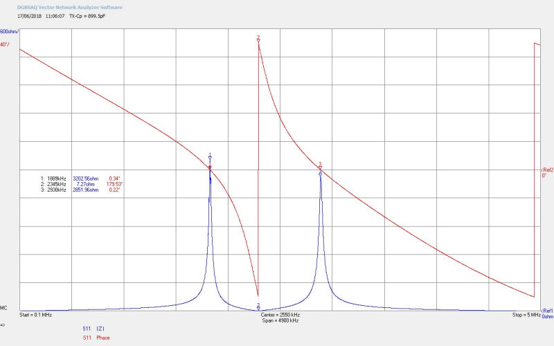
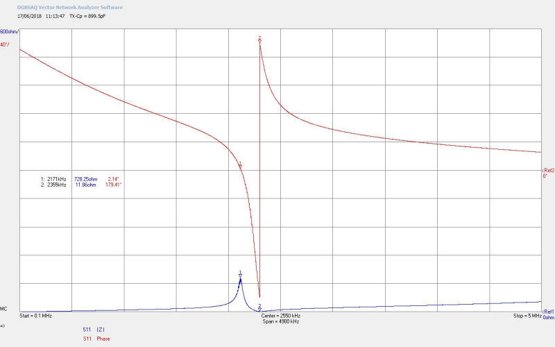
Fig 4.1. Shows the small signal input impedance Z11 as seen by the generator of the complete experimental apparatus with all measurement probes connected, and the fly lead connected at the output of the bulb load. The impedance characteristics show that the experiment tuning is operating very close to the balanced point between the lower and upper resonant frequency, FL and FU, of the flat coil. This is the point where there is expected to be best balance between the electric and magnetic fields of induction between the primary and the secondary coils, and in this case the best experimental starting point when investigating the displacement and transference of electric power through non-linear processes. FL measured when running the single wire current experiments was ~1850kc/s, and from the impedance characteristics 1889kc/s a variation of ~2%, and most likely due to differences between the small-signal and large-signal operation points of the flat coil, tuning components, and generator mode of operation (cw class-C).

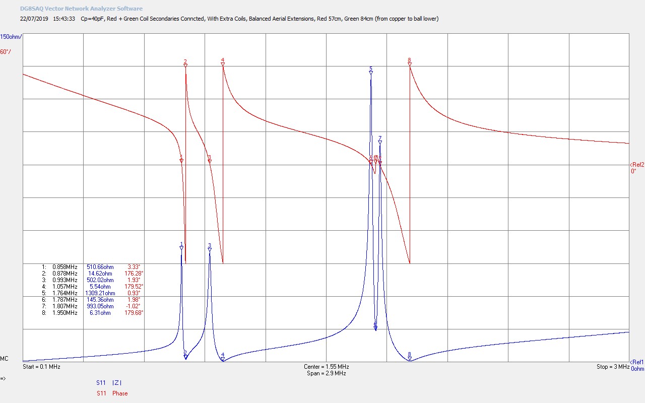
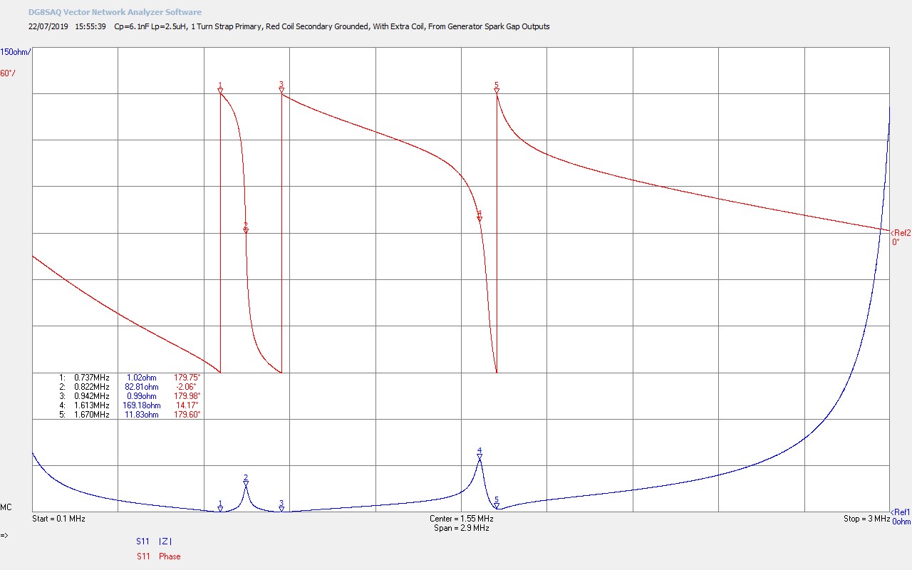
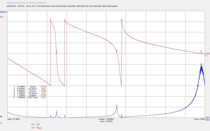
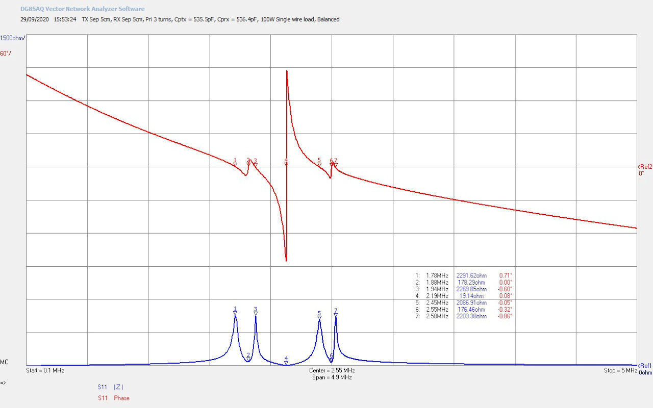
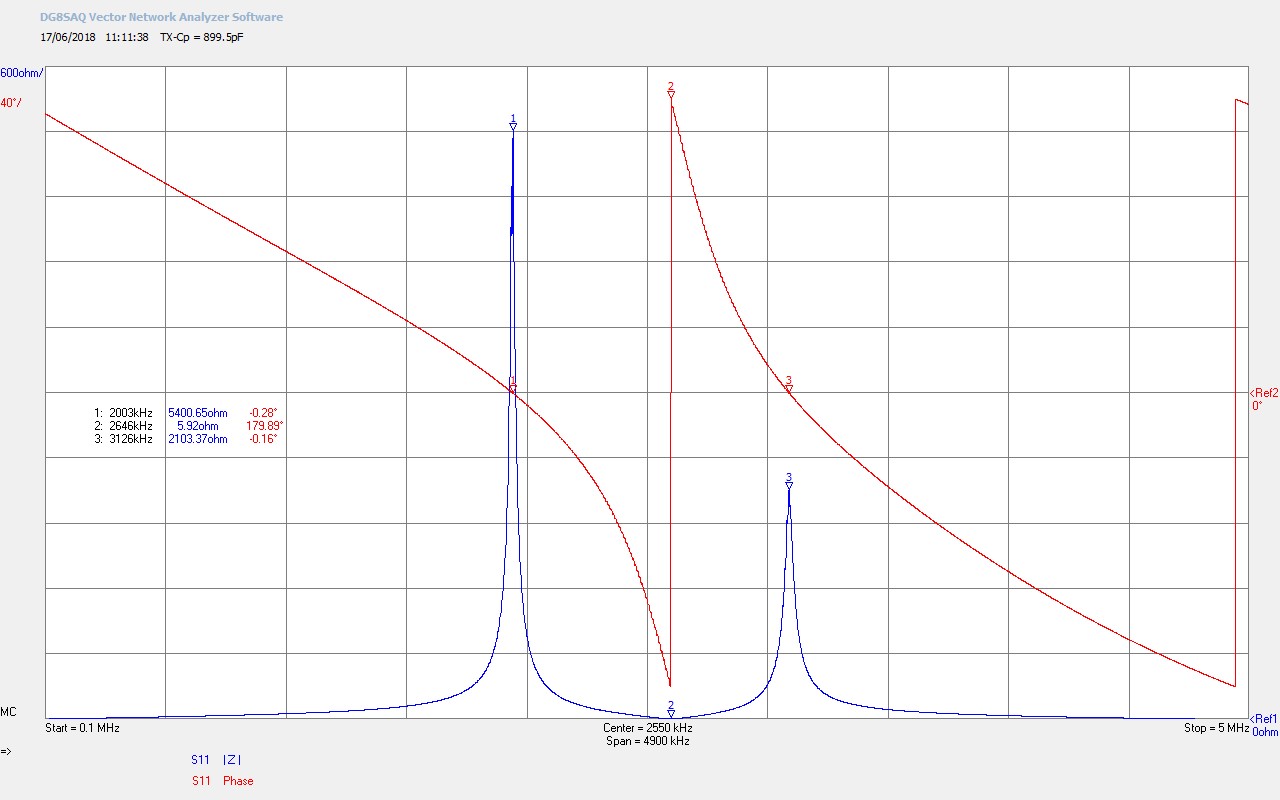
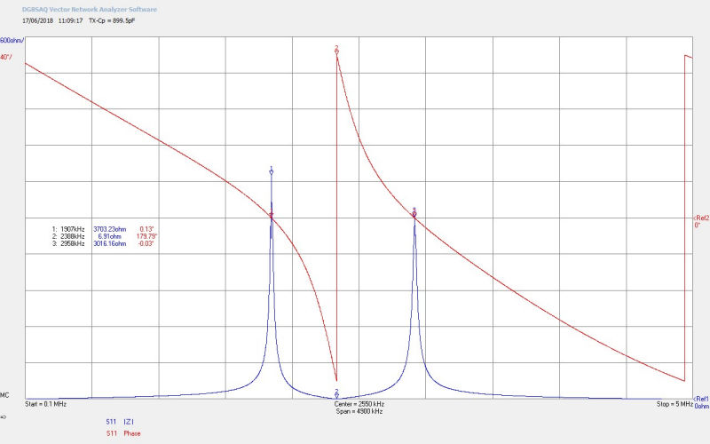
Fig 4.2. Shows the result of removing the fly lead the length of wire in the secondary section of the experiment has been reduced, and hence the frequency increased from ~1850kc/s to ~1860kc/s. This is also indicated by the impedance characteristics where the 180° phase change frequency FØ180 has shifted from 2345kc/s in Fig. 4.1 up to 2388kc/s. This has also created a greater imbalance between  FL and FU.

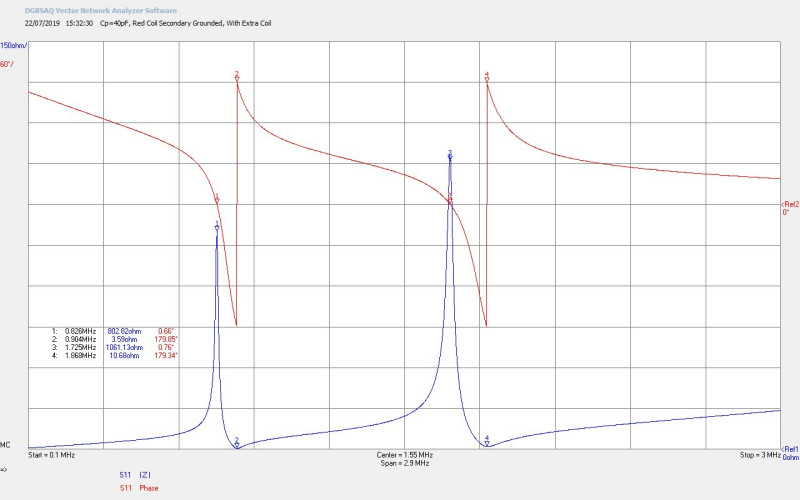
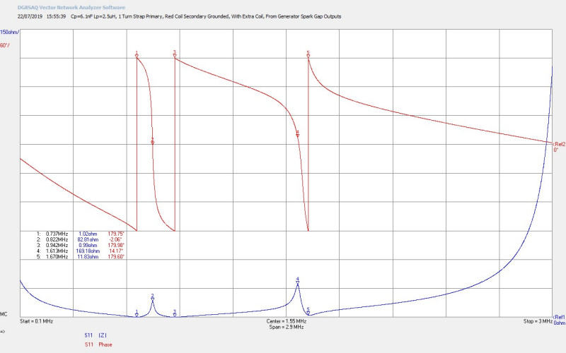
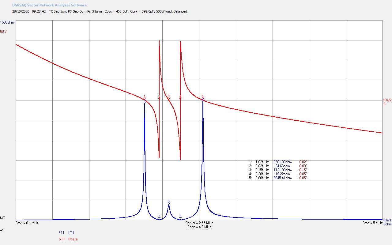
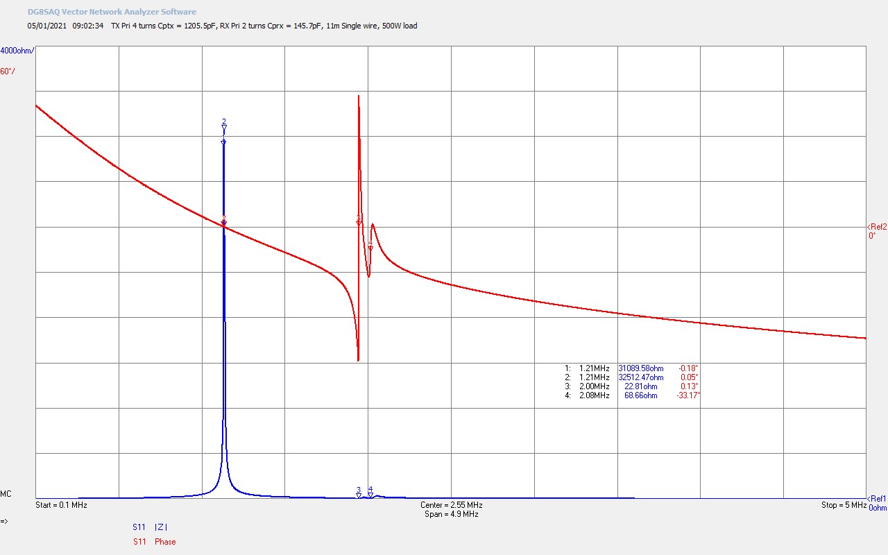
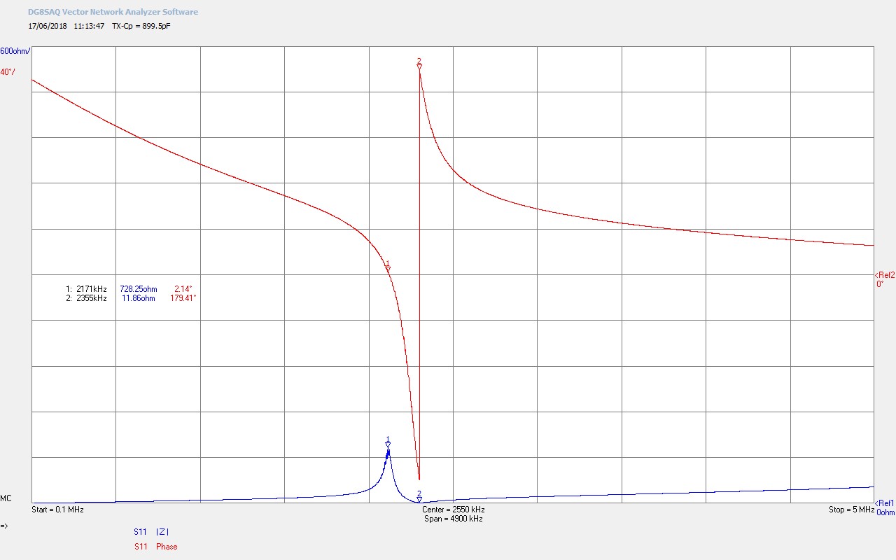
Fig 4.3. Shows the result of removing the experiment from the bottom-end or outer-end of the secondary coil. All frequencies are shifted up due to the change again in wire length, and also the change of impedance at the bottom-end from lower to higher, and away from the λ/4 mode.

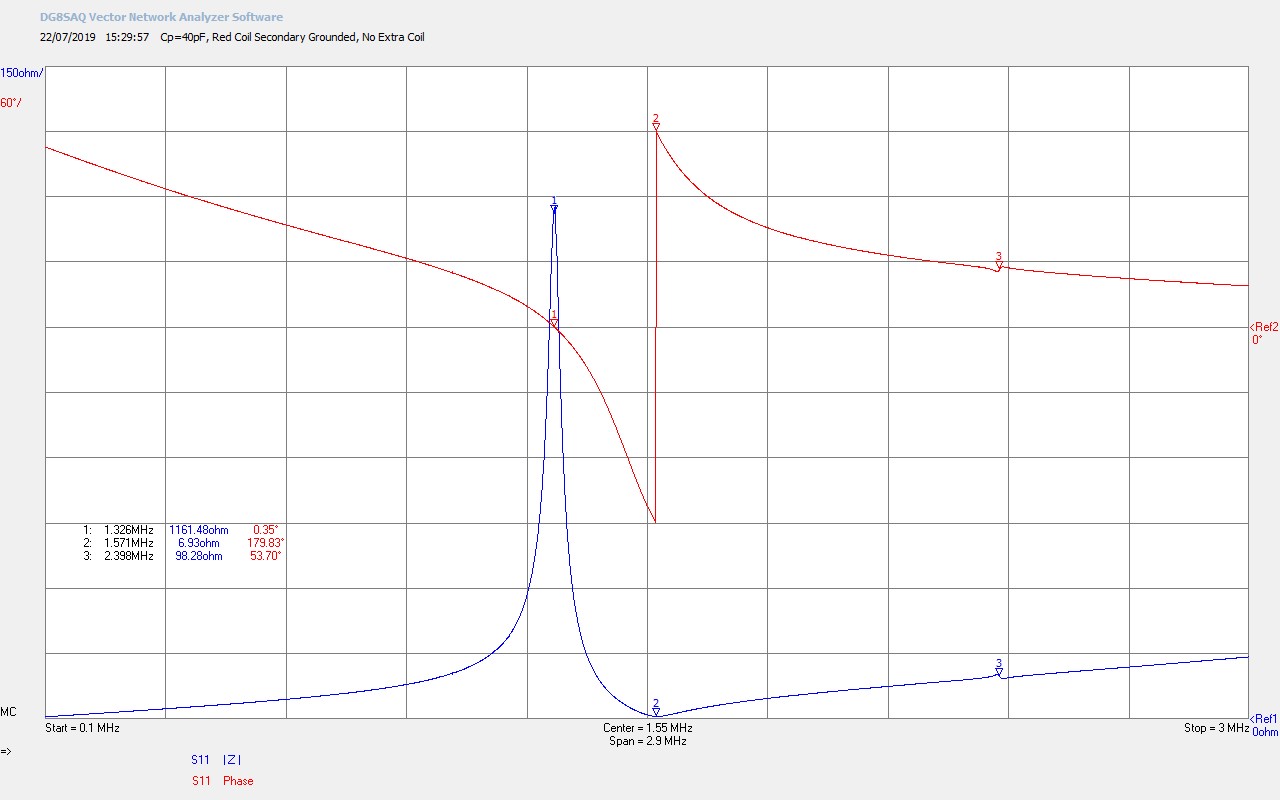
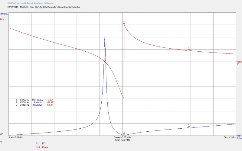
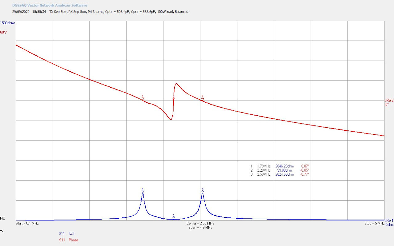
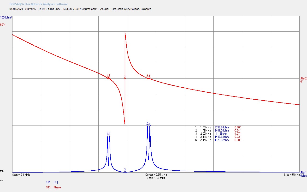
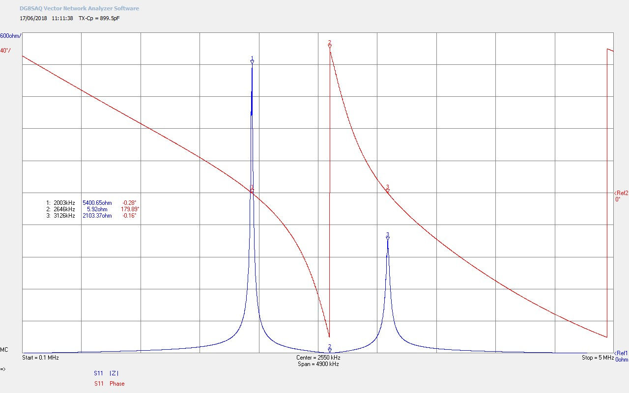
Fig 4.4. With the primary capacitance CP removed the impedance characteristics of the experiment revert to the loaded properties of the secondary coil with a single resonant frequency, and there is no established balance between the electric and magnetic fields of induction between the primary and the secondary.

Summary of the results and conclusions so far:

1. Single wire currents have been observed and measured using a flat coil driven by a vacuum tube generator in cw mode. The current measured in the single wire, and its properties thus far observed, would appear to suggest that rf energy from the wire is escaping along its length to the surrounding environment which acts as an energy sink, ground, or -ve terminal, which then effectively completes the circuit. High energy rf  as a result of the magnified voltage produced by the secondary coil, is easily radiated from all parts of the conductor that forms the wire through to the end of the fly lead. With this being the case, and with the voltage and current being in phase in the secondary, real power is generated to drive the load bulbs which emit both light and heat.  With the fly lead removed the final load bulbs do not light as there is insufficient length of conductor to act as a suitable radiator or sink “to ground”. It is expected that any load connected to the end of the single wire will not be driven as there is insufficient energy sink on the output of the load to enable a current to be developed through the load. With this being the case the energy sink is distributed along the length of the wire so that the current along the wire would not be a constant value, as might be expected normally for the current flowing through a circuit. In part 2 of single wire currents it will be necessary to measure the magnitude and phase of the current along the wire length as a function of distributed load which would then allow a more accurate picture, and hence interpretation, of single wire current action in a circuit.

2. Standing waves were not observed or measured along the length of the single wire in this experiment, but rather the magnitude of the oscillating voltage appears to remain relatively constant along the length of wire, whilst the current reduces with load and distance along the wire. This will be further investigated in part 2 where a more accurate voltage and current distribution will be measured with wire length and load distribution.

3. A force applied to a conductive medium in close proximity to a load on the wire, in this case a lighted incandescent bulb filament, has been observed and investigated at first stage. The phenomena, at this stage, appears to result from a form of electric attraction between the filament of the bulb the emitter, and the conductive medium. The effect does not appear to be influenced by other close proximity magnetic fields such as permanent magnets, and electromagnets, which also suggests that the phenomena does not result from eddy currents generated in the conductive medium. A range of different materials have been tested, and all that show a significant attraction towards the load bulb, have a conductive element or property. The effect is also greatly amplified in the presence of a significant energy sink such as the hand of a person. In cw mode no discernible force could be registered on the surface of the hand when placed in close proximity to a load bulb. This has been subsequently demonstrated when driving the generator in burst or impulse mode and will be presented in detail in subsequent parts.

4. The impedance characteristics indicate that the complete experiment was operated in a well-balanced mode of the flat coil, which suggests a good starting point for further, and more detailed investigation, of the displacement and transference of electric power through non-linear events.

Click here to continue to Transference of Electric Power – Part 1.


1. A & P Electronic Media, AMInnovations by Adrian Marsh, 2019,  EMediaPress

2. Dollard, E. and Energetic Forum Members, Energetic Forum, 2008 onwards.


ESTC 2019 – Tesla’s Colorado Springs Experiment

ESTC 2019, the Energy, Science, and Technology Conference[1], included a presentation and working demonstration by Eric Dollard on Tesla’s Colorado Springs experiment[2] (TCS), which is available through A & P Electronic Media[3,4]. Due to unforseen circumstances relating to the demonstration co-worker, the generator for this experiment was unavailable after the demonstration for additional experimentation, investigation, and follow-up demonstrations. In agreement with Eric Dollard I suggested that the spark gap generator from the Vril Science Multiwave Oscillator Product[5], (MWO), could be adapted, tuned, and applied to the Colorado Springs experiment, and in order to facilitate ongoing investigation and experimentation throughout the conference period. What follows in this post is the story of how this successful endeavour unfolded in the form of videos, pictures, measurements, and of course the final results.

The first video below shows highlights from the endeavour, video footage was recorded and supplied by Paul Fraser, and reproduced here with permission from A & P Electronic Media.

The second video below shows highlights from the impedance measurements part of the endeavour, video footage again by Paul Fraser, and by Raui Searle.

Figures 1 below show a range of pictures of the original transmitter and receiver setup from Eric Dollard’s TCS demonstration, including the generator used to power the experiment, and key results from the original demonstration. The red “transmitter” coil (RTC) was subsequently modified after the demonstration, (secondary coil re-wound, and with a single copper strap primary), in order to work well with the MWO spark gap generator. The green “receiver” coil (GRC) was left un-modified for the purpose of the endeavour, although it could be fine tuned using the extra coil telescopic extension. Ultimately for on-going experiments using the MWO generator, the GRC would be re-wound and adapted to more closely match the RTC.

The original TCS demonstration was powered by a 1000W linear amplifier generator being driven at ~ 800W output to light a 500W incandescent bulb at the receiver primary, and where the electric power is transferred between the RTC and GRC by a single wire. The TCS demonstration with both coils fully configured and connected to the generator was tuned to a drive frequency of 848.4 kc/s, as can be seen in fig. 1.9 as the selected frequency of the transceiver.

The transceiver is an ICOM-7300 which must have been modified to allow transmit on all frequencies, a modification that allows a radio amateur transceiver to generate a transmit signal outside of the designated amateur bands. This kind of modification turns a transceiver into a powerful bench top signal generator, with full modulation capabilities, and matched output powers from the transceiver alone of up to 100W in the MF and HF bands (300kc/s – 30Mc/s). 848 kc/s is in the MW (MF) radio broadcast band, and amplitude modulation is well suited here for the transmission of voice and music signals, as was also demonstrated in the original experiment.

The ICOM transceiver is connected via a matching unit to the Denton linear amplifier. This specific brand and model of linear amplifier has no matching unit at its input, which is why external matching is required from the ICOM 50Ω output to the lower impedance Denton input. The passive matching unit is shown in fig. 1.10, and also in the schematic of fig. 2.1.

The Denton Clipperton-L is a linear amplifier using 4 x 572B vacuum tubes with a band selected matching unit at its output, and a total output peak voltage of ~ 500V. The lowest band provided internally for matching at the output of the amplifier is the HF 160m band at ~ 1.8Mc/s. The much lower MW signal at 848kc/s would need additional matching and balancing between the amplifier output and the input to the primary of the RTC, (the output of the amplifier is an unbalanced feed e.g. coaxial, whereas the connecting transmission line and the primary are better fed with a balanced feed). The amplifier passive matching unit is shown in figures 1.6 – 1.8, and is also shown in the schematic of fig. 2.1.

The various different experiments conducted in the original demonstration included the following:

Fig 1.13. Shows Eric Dollard finding the null electric field region between the RTC and GRC, and using a 6′ domestic fluorescent tube light.

Fig 1.14. Shows Eric Dollard testing the field surrounding the RTC extra coil extension top load, using a helium-neon gas filled tube.

Fig 1.15. Shows single wire transmission of electric power, and fully lighting a 500W incandescent light bulb at the primary of the GRC.

Figures 2 below show the schematics for both the linear amplifier generator and coil arrangement for Eric Dollard’s original TCS demonstration, and a second schematic for the TCS experiment retune using the MWO spark gap generator. The high-resolution versions can be viewed by clicking on the following links TCS Demonstration, and TCS Retune.

Figures 3 below show the small signal impedance measurements for Z11 for the TCS coils, and also the tuning measurements for the coils and spark gap generator together, which were taken throughout the endeavour and used to ensure a well tuned match between the generator and the TCS experiment.

To view the large images in a new window whilst reading the explanations click on the figure numbers below, and for a more detailed explanation of the mathematical symbols used in the analysis of the results click here. For further detail in the analysis and consideration of Z11 typical for a Tesla coil based system click here.

Fig 3.1. Shows the impedance measurements for the RTC with the secondary grounded, the extra coil disconnected, and where the primary tank capacitance has been arranged to be series CP = 40pf, which puts the primary resonant frequency FP at a much higher frequency and far away from the secondary. This would be the proper drive condition for the original linear amplifier generator (LAG) where FP is not arranged to be equal to FS. For the spark gap generator (SGG) it is necessary to match FP as closely as possible to the combined resonant frequency of the secondary and the extra coil together.  The fundamental parallel resonant frequency of the secondary Fs at M1 = 1326kc/s, and as is to be expected with this form of air-cored coil, the FØ180 or series resonant point at which a 180° phase change occurs, is at a higher frequency at 1571kc/s at M2. At M3 = 2398kc/s a tiny resonance is being coupled from the disconnected extra coil which, being mounted in the centre on axis with the secondary, is close enough to have a non-zero coupling coefficient, and hence show some slight resonation reflected into the measurement.

Fig 3.2. Here the extra coil has been reconnected and two resonant features can be noted, the lower from the secondary, and the upper from the extra coil. The effect of the coupled resonance between the two coils with a non-zero coupling coefficient is to push the secondary resonance down in frequency to where the FS at M1 is now at 826kc/s which is very close to the original drive frequency of the linear amplifier generator at 848kc/s. The fundamental resonant frequency of the extra coil, (now in λ/4 mode with one end at a lower impedance connected to the secondary, and the other connected to the high impedance of the extendable aerial), at M3 is now 1725kc/s

Fig 3.3. Here both the RTC and GRC have been connected together to complete the overall system, and where the bottom end of both secondaries are connected together by a single wire transmission line. Both the RTC and GRC have their extra coil adjustable extensions fully extended. It can be seen that both the secondary and extra coil resonant frequencies have been split in two, to reveal four resonant frequencies from the four main coils, 2 in the RTC, and 2 in the GRC. The markers at M1 at 833kc/s and M3 are due to the secondary resonance in the RTC and GRC respectively, and the markers at M5 at 1752kc/s and M7 at 1801kc/s are due to the extra coils. It can be noted that the impedance of the RTC and GRC are not well-balanced the resonance is stronger on the RTC side where |Z| at M1 ~ 741Ω, and M3 ~ 342Ω. During running operation with either the LAG or SGG this would result in more energy stored in the RTC coil, the standing wave null on the single wire transmission line would be pushed away from the RTC and towards the GRC, and less power would be available at the output of the primary in the GRC.

Fig 3.4. Here the lengths of the extra coil extensions have been adjusted to balance |Z| at M1 and M3 at ~500Ω. The RTC extended length was 57cm, and the GRC extended length was 84cm, measured from the copper to aerial join, and to the base of the ball top load. With very fine adjustment, which is very difficult to accomplish, it may be possible to also balance |Z| for the extra coils at M5 and M7. This would result in the ideal balanced and equilibrium state, where the electric and magnetic fields of induction are balanced across the entire system, energy storage is equal, the null point is equidistant between the RTC and the GRC, and maximum power can be transferred between the two coils. In practice, when |Z| for the fundamental secondary resonance is equal, as shown, the overall system can be considered to be well-balanced, and will perform close to its maximum performance. Very slight adjustments to the drive frequency from the generator can then be used to nudge the system into the best overall balance and match. FS at M1 is now 858kc/s which is now close to the original drive frequency of the LAG at 848kc/s.

Fig 3.5. Shows the impedance characteristics of the RTC from the perspective of the SGG. The vector network analyser (VNA) is connected to the outputs of the spark gaps in the generator, so the characteristics include the tank capacitance of 6.1nF and the primary coil, which in this case is 2 turns of 1/4″ copper pipe. It can be seen that the resonant frequency of the primary FP is somewhat below FS as M1 at 549kc/s, and is moving away from M2 and M3. FS has also reduced to 801kc/s at M2 which also shows that the loading in the primary is too much. The inductance of the primary coil, or the tank capacitance, needs to be reduced in order to establish a better match between the generator and the RTC.

Fig 3.6. Here the number of turns of the primary has been reduced to one, which reduces the inductance in the primary resonant circuit with the generator. M1 is now closer to M2 and M3 and the FS has now increased to 819kc/s. The tuning between the generator and the RTC has now swung slightly the other way and the primary is pushing upwards on the secondary characteristics. This state is however a better state of tune than that shown in figure 3.5. It can also be seen that FE for the extra coil is cleaner and less impacted by the primary resonance. Additional fine tuning of the system would ultimately be accomplished by moving one side of the primary connection a certain distance around the circumference of the primary loop, (to form a fractional number of turns in the primary e.g. 1.4), and gain balanced and equidistant spacing for markers M1 and Mfrom M2.

Fig 3.7. Here the single turn copper pipe primary has been replaced with a single turn copper strap, which was deemed to present a lower impedance to the generator, and improve the magnitude of the oscillating currents in the primary. In order to further improve the tuning two 22nF 3kV capacitors in parallel (44nF) were added to one of the outputs of the SGG as shown in the schematic of figure 2.2. This reduced the tank capacitance slightly from 6.1nF to 5.4nF. The inductance of the strap was measured to be 2.5uH which combined with the tank capacitance of 5.4nF provides a theoretical lumped element resonant frequency of 1370kc/s. referring back to figure 3.1 it can be seen that FS, the resonant frequency of the secondary, without the extra coil at M1 is 1326kc/s. So the primary circuit tuned and driven at this point has a very close match to the secondary coil, which ensures that maximum energy can be coupled from the primary to the secondary, and then combined with the extra coil, maximum power can be transferred from the generator to the RTC, and ultimately to the GRC when further connected. For the purposes of this endeavour this state of retune was considered adequate for further demonstration and exploration of the Colorado Springs experiment.

The experimental phenomena observed during the operation of the TCS experiment, retuned to work with the MWO generator, can be seen in the first video on this page.

Summary of the endeavour:

The overall endeavour facilitated the demonstration and exploration of tuning and operating the MWO spark gap generator to work with the Colorado Springs demonstration. In the process the RTC primary and secondary needed to be modified for optimum running with the SGG. Throughout the endeavour a wide range of measurements were demonstrated including:

1. Z11 impedance measurements for the series fed secondary and extra coil, for the RTC.

2. Z11 impedance measurements for the primary combined with the secondary, and the exta coil, for the RTC.

3. Combined Z11 impedance measurements for both the RTC and GRC, where the bottom ends of both secondaries were connected together to form a single wire transmission line.

4. Fine tuning of the system by adjusting the wire length of the extra coil extensions, in order to balance |Z11| in the fundamental and second harmonics.

5. Z11 impedance measurements using a computer connected vector network analyser.

The endeavour also facilitated the demonstration and exploration of the following interesting Tesla related phenomena:

6. Single wire electric power transmission.

7. Longitudinal transmission of electric power.

8. Emission of radiant energy pulses from an incandescent bulb.

9. Radiant energy pulses attracting metal to the bulb.

10. Amplification of radiant energy by interaction with a human hand.

11. Transference of electric power between a TMT “transmitter” and “receiver”.

Click here to continue to the next part, ESTC 2022 – Vector Network Analysis & Golden-Ratio/Fractal-Fern Plasma Discharges.


1. ESTC 2019, Energy, Science, and Technology Conference, A & P Electronic Media , 2019, ESTC

2. Dollard E., Preview of Theory, Calculation & Operation of Colorado Springs Tesla Transformer, 2019, EricPDollard

3. A & P Electronic Media, 2019, EMediaPress

4. A & P Electronic Media, AMInnovations by Adrian Marsh, 2019,  EMediaPress

5. Vril Science, Lahkovsky Multiwave Oscillator, 2019, Vril


Tesla’s Radiant Energy and Matter

Some of the most fascinating areas of research into the inner workings of electricity, are those that display unusual and interesting phenomena, and especially those not easily understood and explained by mainstream science and electromagnetism. The field surrounding Tesla’s radiant energy and matter, the apparatus, experiments, and wealth of unusual electrical, and even non-electrical related phenomena, is a particular case to note. This first post in a sequence serves as a practical and experimental introduction to this area, along with consideration and discussion of the observed phenomena, and possible interpretations as to their origin and cause. It is through working to understand these types of phenomena, often generated in high tension, unipolar, and non-linear electrical systems such as the Tesla coil and TMT transmission system, that the inner workings of electricity can be revealed little by little. That is to say, the outer workings of electromagnetism that account for almost all of those measurable electrical properties that constitute the transference of energy, and hence electric power, between source, load, and the intervening transmission medium, can be peeled back to show a more fundamental, coherent, and guiding mechanism.

This second inner level of electricity’s mechanism and working I consider to be based on the principle of displacement, a coherent and dynamic state extending throughout the common medium, and where the electric and magnetic fields of induction are defined but as yet undifferentiated in their nature. These two undifferentiated facets we can only suppose originate from a yet deeper and hitherto unexplored level of inner workings, where the pressure applied by the one and only force of intent leads to the manifested universe, and all that is both known and unknown.

The differentiation of the electric and magnetic fields of induction lead to the outer manifestation of electricity as we commonly know it, transference, and all the electromagnetic properties and scientific measurements that accompany it, including, for example, the speed of light c in the vacuum, which only currently has a fixed and defined value based on the level it is measured and perceived at. At this outer level of transference, c is measured as a specific value based directly on the inter-action (propagation) of the differentiated electric and magnetic fields of induction. I conjecture that at the next inner level where these fields of induction are defined but not differentiated, that c has not only different measurable quantities, but also comes with qualities and properties that make it a multi-faceted vibration, rather than the simple linear measure of a fixed value.

It should be clear to the reader that in my interpretation of this field of research I see it as not enough to construct experiments, observe phenomena, measure quantities, and then try to fit this to a linear and physical way of thinking about the world, as is the case in mainstream science, and often even in the alternative approaches. I consider progress in this field of research to be a co-operation or union between high-quality science, and a more philosophical or esoteric understanding of the principles and processes of life. Only through new practical knowledge gained through this inclusive approach to life will it be possible to fully reveal, perceive, and utilise the inner workings of progressively deeper levels of electricity.

Such are my conjectures about the inner workings of electricity even at only the next inner level, that as of yet is an unknown mystery to both mainstream science, and the alternative electricity researcher alike. It is for this reason that I find experiments surrounding Tesla’s radiant energy and matter, and associated phenomena, so fascinating, exciting, and awe-inspiring, as they provide an opportunity to progressively take a look “under the hood” at the world of displacement, a hidden world yet to be discovered. A world much more vast in its import and effect than that which we currently observe, understand, and utilise.

In Tesla’s[1] original patent of 1901, No. 685957, he describes his understanding of radiant energy gained from experimentation and observation, and suitable apparatus for utilising this radiant energy:

“My own experiments and observations, however, lead me to conclusions more in accord with the theory heretofore advanced by me that sources of such radiant energy throw off with great velocity minute particles of matter which are strongly electrified, and therefore capable of charging an electrical conductor, or, even if not so, may at any rate discharge an electrified conductor either by carrying off bodily its charge or otherwise.”

“When rays or radiations of the above kind are permitted to fall upon an insulated conducting body connected to one of the terminals of a condenser, while the other terminal of the same is made by independent means to receive or to carry away electricity, a current flows into the condenser so long as the insulated body is exposed to the rays, and under the conditions hereinafter specified an indefinite accumulation of electrical energy in the condenser takes place. This energy after a suitable time interval, during which the rays are allowed to act, may manifest itself in a powerful discharge, which may be utilized for the operation or control of mechanical or electrical devices or rendered useful in many other ways.”

It is clear from Tesla’s own description that he saw radiant energy as a ray or beam-like emanation, that is capable of transferring energy between the emanating source, and a suitably arranged receiver. Under these conditions an electric current could be established when the radiant energy is accumulated in a capacitor and connected to an electric load.

Tesla also states that a suitable time interval is required to allow the rays to generate an action upon the receiver. Tesla conjectures that radiant energy causes minute particle to be thrown of at great velocity, both making a link between radiant energy and matter, and implying that a force can be exerted not only electrically but also physically on a distant body.

In my own experiments into radiant energy I have observed similar phenomena to those described by Tesla including, charging of capacitors from longitudinal wavefronts generated in the single wire cavity of a TMT system, electrical and physical forces exerted on conductors, insulators, and biological specimens placed in proximity to a source of radiant energy emanations, and electric currents and discharges when load circuits are connected to a condenser charged by radiant energy.

The following video introduces the apparatus, experiments, and phenomena that are most often attributed to Tesla’s radiant energy and matter, and which have been successfully demonstrated in the prior art by researchers such as Dollard et al.[2]. The apparatus used in my video can be readily constructed by a competent electrical engineer,  showing that experimenting and researching this fascinating area is accessible to any open-minded individual with the fortitude to undertake an experimental path of discovery regarding the inner workings of electricity. The video demonstrates and includes aspects of the following:

1. The difference in powering a load with a conventional closed-circuit from the primary coil of a spark gap generator, and a single wire from the Tesla coil secondary.

2. The change in properties observed in the load in a single wire with load position, generator matching, and changes in the single wire cavity length.

3. The force exerted on different materials as a result of radiant energy/matter emanating from an incandescent lamp emitter in the single wire load.

4. The different responses of materials to radiant energy emanating from the lamp emitter.

5. The radiant matter pressure wave emanating from the lamp emitter, as experienced by the human hand.

6. Discharge “plasma-like” emanations directly from the lamp emitter to the surrounding medium.

7. Vibration and physical movement stimulated in the lamp filaments when radiant energy interacts with another object in the surrounding medium.

8. Cool lamp glass temperature when emanating considerable light from the lamp emitter, a so-called “cold” electricity phenomenon.

9. Radiant energy charging of a capacitor, accompanied by subsequent discharge in a neon lamp load, showing a “cool” white-bluish discharge, and a violent snapping sound.

10. An initial consideration of the inter-relationship between the longitudinal and transverse modes of electricity in the single wire load.

11. The transformation of energy from the longitudinal mode to the transverse, and the dissipation of this energy as power in the single wire load.

Figure 2 below shows the schematic for the generator and experimental apparatus used in the video. The high-resolution version can be viewed by clicking here.

Figure 3 below shows the secondary pulse burst at the single wire load measured using a 40kV high voltage probe whose input terminal is placed closed to the load via a short fly-lead. The fly-lead was initially connected directly to the load but caused some interference and erratic operation to the measurement equipment, as shown in the video. This erratic operation results from transient current spikes induced directly through the probe connections to internal circuitry, and cross-coupled amongst the various earth connections in the equipment line-supply. Individual ferrite chokes can be used on the measurement instrument line supply cables to prevent this undesirable cross-coupling. In this case the fly-lead of the probe was simply disconnected from the load but left in close proximity to the measurement region, which had no detectable impact on the measured results, but sufficiently reduced the unwanted interference to allow for correct instrument operation.

It can be seen from the secondary pulse burst that transients in the single wire during the initial spark discharge are large in amplitude, (up to 40kV in voltage magnitude, and 100s of amps in current magnitude), and resemble impulse-like spikes with very short life-times, densely packed in time, and with very short duty cycles. These transient impulses give rise to both sinusoidal oscillations in the resonant circuit of the secondary, and as expected for a Tesla coil or TMT apparatus, stimulate generation of the characteristic longitudinal wavefronts in the cavity of the secondary circuit. As considered in previous posts, the longitudinal wavefronts themselves could result from the coherent spatial inter-action between the electric and magnetic fields of induction in the LMD mode, and where the coherent aspect is the direct consequence of underlying displacement events.

It is conjectured, and explored here, that high-energy transient impulses, that are ideally unidirectional in nature, and characterised by very large amplitudes and very short life-times, stimulate through non-linear processes electrical events or an imbalance in the system that needs to be, and can only be, rebalanced by the underlying coherent process of displacement. The product of this momentary exposure to displacement, (or an inner-working of electricity), is emission of the rays or beam-like emanations Tesla referred to as radiant energy, which in-turn give rise directly to the unusual electrical phenomena observed in the experiment. It is to be conjectured that the observed radiant energy emanations are directly the consequence of a displacement event taking place in the non-linear dynamics of the local electrical system.

With this conjecture stated the various experimental observations shown in the video will now be considered with the objective of determining their possible source or cause, and in order to get a better qualitative understanding of the underlying principles and processes involved. It should be noted that real experimental results, observations, and perceptions are being conjectured here into a possible underlying explanation, which will need considerable further consideration and experimentation to test, verify, and draw reliable and robust conclusions as to the validity of the considered conjecture.

Transference of electric power in closed and open-circuit systems

The dissipation of power in an “open-circuit” or single wire load is a very characteristic phenomena which can be readily observed and measured in almost any Tesla coil geometry and configuration. A suitable resistive load such as an incandescent lamp can be made to illuminate brightly when connected by a single terminal to either end of the Tesla coil, and the other terminal of the lamp has a small wire extension or fly-lead added. Without this fly-lead the lamp is at the very termination of the single wire and it will not illuminate or dissipate power.

This single wire power dissipation can be observed irrespective of how the Tesla coil primary is energised, whether it be from a sinusoidal linear amplifier or oscillator, a burst discharge from a spark gap, or a pulse generator. In other words, provided the primary and secondary coils are arranged to couple sufficient energy between them it does not matter whether this energy is from a single frequency linear sinusoid, a burst discharge envelope, or a set of non-linear transients, pulses, or impulses, it is possible to dissipate this coupled power within a resistive load placed in the single wire extension of the secondary coil.

It can be seen in the video that the lamp load could not be made to illuminate when connected to output taps on the primary side of the Tesla coil, even on the “HI” Oudin extension terminal. The tension on these primary side terminals is high, about 1kV on the LO, 2-4kV on the MID, and up to almost 10kV on the HI terminal. There is also a wide range of frequencies in the pulse burst due to the spark discharge in the primary circuit, so the output of these primary terminals is certainly a high tension RF burst discharge. This RF burst looks very similar in envelope shape and structure to that measured in the secondary, with the major exception that the oscillation within the burst envelope is dominated by the primary circuit characteristics, whereas in the single wire it is dominated by the secondary coil circuit characteristics.

Given all of this the lamp load will not illuminate and dissipate power when connected by a single wire extension to the primary side terminals, and yet will readily illuminate when connected by a single wire extension to the secondary coil. The only way found to illuminate the load when connected to the primary side terminals is to complete the circuit by connecting the single-wire extension back to the primary ground terminal, making a normal closed-circuit system.

A very similar example to this would be powering an incandescent lamp when placed across the output terminals of an oscillator, or even better in the coaxial transmission line between the output of an amateur radio transmitter tuned to transmit say in the 160m HF band (~2 Mc), and a half-wave dipole antenna at the far end of the coax. When the coax is connected on both terminals (circuit-closed) the lamp will light and dissipate some of the power from the transmitter dependent on the impedance it presents within the circuit, with the remaining power being radiated from the antenna and consumed by the coax. When either terminal of the coax is removed (open-circuit) the lamp will not light and no power is dissipated in either the lamp, or delivered to the antenna.

This most simple, and yet profound difference, between powering a load from the primary and secondary circuits of a Tesla coil, where both coil outputs are high tension and contain considerable RF energy, suggests a fundamentally different mechanism of electrical transmission and/or dissipation of power in the two cases. In the primary the system behaves exactly as one would expect for a conventional electrical circuit, and can be measured and calculated precisely in the case where a linear sinusoid is applied to the circuit. If we reduce all electric circuit characteristics to the inter-dependent relationship of the electric (or dielectric) field of induction (Ψ), and the magnetic field of induction (Φ), and their inter-action with material type, form, and structure, then it should be clear that there is a fundamental difference in the relationship, or mode of inter-action, between these two induction fields within primary circuit and the secondary circuit.

In the closed-circuit case the configuration of Ψ and Φ lead to voltages and currents distributed in time around the circuit that are transverse in nature and where the phase relationship between them is distinctly defined by the impedance elements, (boundary conditions), distributed in the overall system. In this case or mode Ψ and Φ are fully differentiated, non-coherent, not in-phase either spatially or temporally, and only becoming temporally in-phase in the transverse electro-magnetic (TEM) mode for far-field propagation.

In the open-circuit or single wire case and to dissipate power in a load it is necessary for the configuration of Ψ and Φ which are still fully differentiated, to be coherent, that is in-phase spatially and temporally. This can be accomplished through the longitudinal mode, or the LMD  mode as it is known, where both Ψ and Φ are locked in phase alignment with each other, and form a combined traversing wavefront within the cavity, generating an electrical pressure wave ahead of the combined wavefront.

In this case local changes of impedance on the single wire, such as the filament of a lamp, lead to power dissipation at the pressure wave through local generation of instantaneous voltages and currents within the impedance change, and hence power dissipation, light, and heat. It can be seen that rms current decays in magnitude along the length of an open-circuit terminated single wire longitudinal cavity, rather than stay constant as would be expected for a transverse mode circuit. With the lamp as the termination of the single wire cavity it will not light as the local current in the wire end has reduced to zero, and no power can be dissipated in the load in the transverse mode.

In summary for now, the most basic Tesla coil presents a fundamentally different power transmission mode at the secondary coil, that is irrespective of how it is energised in the primary circuit, and is most likely longitudinal in nature, and results in the phenomena of single wire transmission of power.

Attractive and repulsive forces

The video shows a range of different materials mounted in a pendulum-like arrangement, that when brought in to close proximity to the single wire lamp load emitter, experience an attractive and in the case of certain materials, an additional repulsive force. The attraction of a material can be almost instantaneous on application of the emitter power, or in some cases can take a period of “charging” time to reach a sufficient level to pull the material towards the surface of the emitter. In most material cases the sample is retained on the surface of the lamp for a period of “discharging” time before being released from the surface after the emitter power is turned off. The responses of the different materials to radiant energy and matter emanations from the lamp are as follows:

Aluminium – attracted towards the emitter over a distance of up to 20mm with an electrical power level at the lamp of ~40W, (power present at the emitter lamp is estimated based on its relative brightness when illuminated at 100% of its nominal rating of 25W). 10mm at ~20W was demonstrated on the video, and this material is readily retained on the emitter surface after power off. No repulsion events were observed with this material.

Copper – both attracted and repulsed from the surface of the lamp at a distance of ~8mm at ~20W. This material is more gently attracted to the emitter but is more unlikely to be retained on the surface. The most observed phenomenon is that the copper in coming into contact with the lamp glass is then repulsed quite strongly from the surface rather than being retained on the surface. The repulsion has a defined force rather than a simple falling-away or bouncing off of the glass surface. The attraction and repulsion at the correct distance from the emitter leads to a sustaining mechanical oscillation of the pendulum.

Acetate (cellulose) – not attracted towards the emitter even at distances <1mm at up to 50W of emitter power. However at much high powers >100W with a different lamp, very small movements have been possible in the region of ~1mm from the lamp surface. Slow to attract over the distance, and very quick to release, implying very low pull force, and very low charging effect.

Biomatter (fresh and dried) – in this case both a fresh and dried leaf sample were strongly attracted to the lamp  over a distance up to 20mm at ~20W. This material gives the most instantaneous response to emitter turn-on with very rapid movement to the lamp surface. This material is also barely retained on the lamp glass after emitter turn-off, being almost as quickly released as it is attracted to the surface. No repulsion events were observed with this material.

Cardboard – in this case the cardboard is very old originating from the original inner box of a Weston 425 meter, and showed good attraction up to 5-10mm  at ~20W. This material is not retained on the lamp glass after emitter turn-off, and no repulsion events were observed with this material.

Clearly from this experiment it can be seen the emanations from the lamp emitter result in a physical force exerted on the material. This physical force is attractive for all of the materials, including the acetate, but varies very widely in scale based on the material type. Surprisingly the biomatter exhibits the strongest attraction, followed by the metals, all the way down to the insulator with only very small attraction at much higher powers. Only the copper shows a sustained repulsive force but only after an attractive event has first pulled the material to the surface of the glass of the lamp, almost as though an inversion occurs at the surface contact and the material is then repelled away. There is no situation where a material has been repelled away from the lamp at turn-on without first being attracted to the surface.

By studying the nature of the experiment it does at first appear like a “charging” effect. Emanations or wavefronts emitted from the lamp emitter cause negative charge accumulation at the surface of the material, where the degree of surface charging depends on the material type, its “impedance” to the emanations, and the material conductance. If this where the case it would be similar to an electrostatic force where two or more materials are attracted or repelled by the difference in their surface state charge.

It has been suggested[3] that the attractive force is magnetic in nature stemming from eddy currents generated in the material by the incident emanations. I have not so far been able to demonstrate this since the introduction of a strong bar magnet into the experiment makes no difference either attractive or repulsive to the material under test. The material still behaves as indicated above, and at the same power levels and distances, irrespective of the magnets influence on the experiment. However, this is not to say that the magnetic field of induction Φ is not involved in this process. This can also be partly supported by the observed sustained current through a neon lamp load in the capacitor charging part of the experiment, which could suggest that both Ψ and Φ are present within the nature of the radiant energy emanation.

At an empirical level this would appear to make sense, if the radiant energy is an emanation resulting from a displacement event at the emitter, and the displacement event involves the undifferentiated Ψ and Φ acting in temporal and spatial coherence, it would correspond that the emanation from this event is in phase, longitudinal in nature, and forms a forward moving unidirectional wavefront of “electrical pressure”. In this way this emanation conveying both Ψ and Φ when incident on materials within the transmission medium could stimulate an electric, magnetic, or a combination response from the material. This stimulated response may involve energy accumulation and storage, and also dissipation of energy through exertion a physical force, electromagnetic emission or absorption (light and dark), thermodynamic changes (temperature or pressure changes), or even perceptual changes of the surrounding medium.

As a coherent pressure wave its transmission over distance may be very large, transferring energy from the pressure wave to incident materials in the surrounding medium, or even becoming self-sustaining with distance through amplification from suitably arranged material forms and apparatus. The velocity of the pressure wave needs to be considered and suitable apparatus for its measurement arranged, however in the coherent state as an emanation from a displacement event it is considered possible that energy is displaced between source and load at velocities exceeding c the transverse electromagnetic speed of light in the vacuum.

In summary, radiant energy like emanations very similar to Tesla’s original observation in his patent, can be observed from a suitable load, (impedance change), placed in the cavity of a single wire transmission medium. These emanations are conjectured to be the product of coherent underlying processes which stimulate a range of different responses from incident materials. The emanations are conjectured and discussed to be directly the product of displacement events generated by longitudinal electrical pressure imbalance at the single wire load.

Low temperature light emission and “cold” electricity

In Lindemann[4] the term “cold electricity” was used to describe experiments and observations by Gray (via Valentine)[5], based on light emitted by incandescent lamp loads, which was not accompanied by the normal rise in temperature expected from this type of resistive load, but rather the lamp had a cool glass surface when emitting “full power” illumination. Gray further demonstrated this by illuminating to full power an incandescent lamp submerged in cold water, which would ordinarily lead to fracture of the lamp glass. In the case of illumination by “cold electricity” no such fracture damaged was observed over sustained illumination periods.

In my experiment with incandescent lamps in the single wire load it was observed that the temperature of the lamp was quite low, and could comfortably be touched or held by the human hand after sustained illumination, equivalent to illumination at a full input power of 25W. This was compared to a control lamp, (same 25W pygmy make and style), powered from the normal line supply. After the same period of illumination where both lamps appeared the same brightness, the lamp in the single wire could be easily touched and held, whereas the control lamp was too hot to touch without causing a burn to the skin.

It appears likely from this experiment that the light being observed in the single wire lamp is, at least in part, emitted by a different process than the control lamp. Continuing the consideration from the previous section, and looking at the response of different materials to radiant energy emanations, it is possible to imagine that the filament of the bulb as a material that radiant energy is impinging upon, has its own unique and specific response to the coherent pressure wave emanation. In this case the response of the material to the radiant energy is to emit electromagnetic radiation in the form of light, which was not entirely generated by the resistive heating of the filament from the electrical current flowing in the single wire.

In a normal transverse and closed electric circuit case an incandescent lamp will generate light as emission from a resistive heated filament, where the colour temperature of the light is based on the filament material and temperature. Heat from radiation and conduction through the gas in the lamp heats the outer lamp glass to a temperature more than sufficient to cause sustained burns to biomatter. In the single wire lamp load light appears to be emitted through the filament response to the coherent longitudinal wavefront, which does not result entirely from resistive heating of the filament. Since the lamp does warm a little there is most likely a combination of processes going on, so some light emanation from radiant energy coherent processes, and some transverse current resistive heating in the filament.

This implies that there is a combination of the longitudinal and transverse electrical transmission modes within the single wire. It follows that improvement of the experimental system and boundary conditions could lead to a reduced transverse component, and a more pure longitudinal pressure wave in the single wire cavity reducing the heat emitted from the load to a level comparable to that observed by Gray in his experiments. In this case we would expect the temperature of the single wire lamp load to reduce from slightly warm to very cool, or even to cold in optimal experimental conditions and apparatus. Optimal conditions here means firstly reducing the transverse components within the single wire, which implies establishing the stable balance of Ψ and Φ boundary conditions in the complete system across the generator, primary, secondary, and cavity. And secondly it requires an increase to the uni-directional impulse like nature of the stimulus, where the increased non-linear inter-action between Ψ and Φ results in more displacement events and hence stronger emanations from the emitter.

In summary, it is considered that radiant energy emanations on the filament result in emission of light which is in part not as a result of resistive heating of the filament, which shows a similar result to that reported by Gray and considered by Lindemann. Improvements to the experimental apparatus and operating conditions should result in an increase in this phenomena, and will also help to confirm the validity of the conjectures made regarding displacement and radiant energy. It should be noted here that whilst I understand the label of “cold electricity” given to this phenomena, I find that the process conjectured here as being responsible for this phenomena is definitely not a “cold” principle. “Cold” in these terms implies the absence of something or something separated, in this case the energy to elevate the temperature through transverse dissipation, whereas I consider the emission of radiant energy, and the filament material response to that emission, to be an inclusive process which involves the coherent inter-action of both Ψ and Φ.  Thus phenomena and emanations resulting from displacement are inclusive in nature, involve all parts of the system and medium in dynamic balance, and imply a sense of warmth, wholeness, and completeness.

Radiant energy accumulation and charge storage

In this experiment a capacitor is electrically charged by radiant energy emanations, showing energy transferred from the single wire emitter, accumulated in the capacitor, and then discharged through a neon bulb in the form of a spark discharge. In many ways this a similar consideration to the section on attractive and repulsive force, only additional accumulation can occur due to the capacity and storage of energy on the capacitor, which persists for much longer time intervals after the radiant energy emitter has been turned off.

An interesting observation to note from this experiment is that during the “charging” of the capacitor a smaller single wire circuit, or tributary from the main cavity, is created in the form of the capacitor in close proximity to but not touching the lamp, a wire connected to the other terminal of the capacitor, and a neon lamp load connected to the end of this wire. The active region of the neon lamp appears in the cavity tributary where there is also a short lead out of the neon lamp acting as the short fly-lead at the end of the single wire cavity, and ensuring there is a small but non-zero single wire current in neon load. During the charging stage the neon bulb lights continuously showing a single current flow down the tributary, and the transient like nature of the accumulating tension on the capacitor.

When the capacitor is adequately charged the main single wire load emitter can be turned off, and the charged capacitor and tributary circuit removed from the vicinity of the main experiment. The charge of the capacitor is retained over considerable time without any part of the circuit being closed with the neon bulb. When the circuit is closed the stored energy discharges rapidly through the neon bulb, with a characteristic snapping sound, and a bright bluish white discharge light in the neon bulb. The nature of this spark discharge shows that there is considerable tension on the capacitor, in fact it can be measured using a high voltage probe to be up to ~10kV, and considerably more than the maximum rating of the capacitor, (in this case 4kV). Unusually the capacitor appears unaffected by application of this overall tension across its terminals, and can provide a rapid and high-current discharge through the neon bulb.

In summary, energy can be stored in a tributary single wire circuit incorporating a capacitor as an accumulator, when a radiant energy pressure wave is incident on one terminal of the capacitor. The experimental arrangement used with the load attached by single wire to the other terminal of the capacitor, and kept open-circuit during charging demonstrates the possibility of the formation of single wire tributary cavities, which extend off the main cavity. In some ways this is similar in analogy to the “fern” discharge effect demonstrated by Dollard[6], when exploring extra-coil discharge phenomena with a pair of cylindrical phase-locked TMTs.

Radiant matter pressure on biomatter and reaction forces

In this experiment I placed my fingers close to and around the single wire lamp emitter but not touching, and not close enough for a high tension discharge to occur between the filament and my fingers. It was clear to experience a vibrating pressure exerted on my fingers in similar accordance to Tesla’s observation that “… sources of such radiant energy throw off with great velocity minute particles of matter …”, Tesla[1]. This radiant matter appeared to exert pressure on my fingers, or at least the experience of pressure waves as if being struck by waves of minute particles.

In addition to this I observed, and can be seen on the video, a reactionary force exerted on the filaments of the lamp emitter so that they would move permanently into another position, or else oscillated around a median position until filament breakage or becoming stuck to the inside surface of the lamp glass. Either way the movement of my fingers around the glass of the lamp resulted in both the experience of an exerted physical force on them, and simultaneously a reactionary force exerted on the filaments.

Although Tesla was clear about the nature of these “great velocity minute particles of matter”, I am not convinced of this explanation in this experiment, but rather that the experience is similar to that observed in the section on attractive and repulsive forces, where both Ψ and Φ are coherently inter-acting to form an emanation where again the stimulated response may involve energy accumulation and storage, and also dissipation of energy through exertion of a physical force, electromagnetic emission or absorption (light and dark), thermodynamic changes (temperature or pressure changes), or even perceptual changes of the surrounding medium.

Longitudinal and transverse mode coupling, or transformation, in a single wire cavity

This is a complex topic but one that needs to be initially considered here if we are to move toward a proper understanding as to the principles of transmission that take place in a single wire conductor, its relationship to the transverse and longitudinal mode, and ultimately the underlying stimuli and inner workings of electricity, displacement, and radiant energy.

In experiments and discussions thus far the Tesla coil or TMT system has been considered to form a cavity in the secondary circuit, where single wire transmission medium phenomena can be easily observed and measured. It has been suggested by others[2,3] and conjectured by myself that the single wire open-circuit nature of these phenomena, is a result of the longitudinal mode of transmission in the cavity created within the TMT system, where both Ψ and Φ are coherently locked in phase, creating an electrical pressure wavefront that traverses the cavity between boundaries, being reinforced by successive oscillations from the primary, and either transferring the power to a distant load in the primary of a receiver, or dissipating the energy in the wavefront within a load of different impedance within the single wire cavity.

The frequency of this longitudinal mode is expected to be different from the transverse resonant frequency of the Tesla coil secondaries for both the transmitter and receiver coil in a matched and tuned TMT transmission system. Whilst impedance measurements on a TMT with a vector network analyser, reveal in minute detail the transverse mode inter-action of the various resonant circuits making up the overall system, it appears to show nothing of the properties of the longitudinal mode which lay outside of its measurement paradigm. The concept of a longitudinal wavefront where both Ψ and Φ are temporally and spatially in phase does not currently exist in modern electromagnetism, and there is not an instrument currently available for probing this mode and condition.

Still the question stands of how it is possible to dissipate power in a single wire load in a longitudinal cavity. To start to address this we must consider the coupling between modes in the local impedance change of the load. Whilst the longitudinal mode of transmission dominates in the single wire cavity, energy and hence power can be transferred to distant loads, with in principle very low loss. To dissipate as power in the single wire load, rather than transfer the energy in the longitudinal mode, a coupling or transformation to the transverse mode must occur, generating local voltage potential difference and local currents in the load, which in turn are consumed as power in the resistive load, such as the filament of an incandescent lamp. I conjecture that it is this transformation process between modes that is characteristics of a single wire transmission medium, and allows for loads to be powered in an open-circuit condition, something that would not be possible in classical electric circuit theory or practice.

Radiant energy as emission from a displacement event

Further to this transformation between the longitudinal and transverse modes in the open-circuit single wire conduction model, it is conjectured and to be explored as a central concern in this research that as the TMT system becomes more non-linear, and when properly arranged to be stimulated with high-power impulse transients, displacement events required to rebalance the local Ψ and Φ dynamics of the system give rise to radiant energy emanations. These emanations result in many of the observed phenomena presented in this post, and when properly arranged in timing, amplitude, and duration lead to a very wide range of perceptual phenomena that are both electrical and non-electrical in nature, and yet to be explored.

So it is maintained and to be explored that the ideal TMT system is one that is carefully balanced, matched, and tuned between the “transmitter” and “receiver” coils both for the longitudinal and transverse modes, such that the single wire transmission medium forms a low impedance, reciprocal, and high Q cavity, where Ψ and Φ are dynamically balanced and in equilibrium for the linear case. This ideal TMT system when subsequently powered by a highly non-linear, uni-directional, transient impulse generator of very high tension, will cause such large discontinuities in the local balance of Ψ and Φ that displacement, as an underlying guiding mechanism in the inner workings of electricity, will be called-forth to re-balance the local dynamics of the electrical system.

These displacement events generate emanations, or electrically based shock waves, that are themselves longitudinal in nature, where both Ψ and Φ are coherently locked in phase, creating an electrical pressure wavefront that emanates outwards from the primary event. the stimulated response of materials and forms which encounter the incident wavefronts may involve energy accumulation and storage, but also dissipation of energy through exertion of a physical forces, electromagnetic emission or absorption (light and dark), thermodynamic changes (temperature or pressure changes), or even perceptual changes of the surrounding medium.

The creation of such an experimental system to test these assertions on displacement and transference, transformation of the longitudinal and transverse modes, and transmission of electric power to distant loads with very low loss, represents a challenge equivalent to surmounting a mountain higher than the highest yet ascended.

Summary of the results and conclusions so far

In this post we have experimentally observed a wide range of phenomena that are usually attributed to those related to Tesla’s radiant energy and matter, and which have also been demonstrated and observed by other significant research efforts, including Dollard et al.[2]. It is clear from the experiments and observations that improvements to the TMT experimental system will facilitate a far more detailed and clear exploration of the underlying principles involved.

In considering the unusual observations of the experiment, and the accumulated understanding of the prior art through both my own collective work presented so far, and that of significant others[1-8], I have formulated a line of conjecture which combines both a philosophical and scientific approach towards the origin or source of these phenomena, and how that source could give rise, through fundamental principles and processes, to the materially observed effects of said experiments.

The formulated line of conjecture has the following key points:

1. The underlying origin or source of these phenomena resides in the inner workings of nature that, at the deepest conceivable level, is the result of the pressure of life’s intent, which in turn gives rise to the need for the natural and living world to evolve.

2.  The inner workings of electricity, as a part of the inner natural world, includes the undifferentiated fields of electric and magnetic induction Ψ and Φ, which act as one together in a fully inclusive manner, and which I refer to as displacement Q. Dollard[8] refers to a similar principle Q as the Plank, or total electrification, which for me reflects the same inner workings of electricity.

3. A displacement event is not normally observable in the differentiated dynamics of Ψ and Φ. This differentiation between Ψ and Φ, and all the implications of their temporal and spatial inter-action results in what science currently understands as the field of electromagnetism, and gives rise to all the phenomena that I refer to as transference.

4. A severe imbalance created between Ψ and Φ in a circuit system where the “need” or purpose of the circuit is clearly stated, and where equilibrium cannot be re-established through the process of transference, will call-forth the underlying guiding principle of displacement. The act of displacement coherently puts the differentiated Ψ and Φ into their proper temporal and spatial alignment, upon where transference can resume as the external and observable dynamics of electricity.

5. The result of a displacement event is to generate an emanation or shock-wave, which Tesla called radiant energy, that permeates the medium surrounding the displacement event, and extending out until all emanation energy is stored or dissipated by external transference of electric power.

6. The radiant energy emanation is a direct consequence and extension of the displacement principle, and equivalent to bursts of energy or electrification injected into the surrounding medium. Suitable collection or reception of this emanation, when introduced to a load suitable to balance the overall system, will make it possible to harvest this additional electrical energy for suitable means, provided the overall balance of the complete system and medium is not violated. This is similar to what Tesla[7] referred to “… it is a mere question of time when men will succeed in attaching their machinery to the very wheelwork of nature”.

7. The radiant energy emanation where both Ψ and Φ are coherently inter-acting leads to stimulated responses from material and forms in the surrounding medium, where the stimulated response may involve energy accumulation and storage, and also dissipation of energy through exertion of a physical force, electromagnetic emission or absorption (light and dark), thermodynamic changes (temperature or pressure changes), or even perceptual changes of the surrounding medium.

8. The extension of radiant energy into the surrounding medium, and when incident on another open single wire circuit with established purpose, will constitute a tributary event, and transferring the same electrical event properties to the tributary, where the quantity of transferred energy is equivalent to the load or need of the tributary circuit.

9. The overall balance and natural order of the electrical system will be maintained through the inner workings of electricity and the principle of displacement, and can be observed and experimented with. Ultimately the energy generated through displacement can be utilised where the natural order and balance is preserved by the utilisation. This is equivalent to where the load represents a need that is inclusive to the system, then the system becomes regenerative, and can self-sustain with energy being supplied to all loads in balance.

This post has opened and exposed many further questions surrounding all of the observed phenomena, the need for much more measurement detail, further design of a more optimal experimental system, and most importantly the verification, or otherwise, of each and every one of the conjectures made to explain and understand what might be the source and mechanism behind Tesla’s radiant energy and matter.

In the next post in this series I will be take a look at improvements to the TMT experimental apparatus that may lead to more detailed and clearly defined measurements to support aspects of the formulated line of conjecture.


1. Tesla, N., Apparatus for the utilization of radiant energy, US Patent US685957, Nov. 5, 1901.

2. Dollard, E. & Lindemann, P. & Brown, T., Tesla’s Longitudinal Electricity, Borderland Sciences Video, 1987.

3. Dollard, E. and Energetic Forum Members, Energetic Forum, 2008 onwards.

4. Lindemann, P., The free energy secrets of cold electricity, Clear Tech, Inc., 1st Ed, 2001.

5. Valentine, T., Man creates engine that consumes no fuel, The National Tattler, July 1, 1973.

6. Dollard, E., Etheric discharge from Eric Dollard’s tesla magnifying transmitter, Integratron, Summer 1986.

7. Tesla, N., Experiments with alternate currents of high potential and high frequency, Address to the Institution of Electrical Engineers, London, Feb. 1892.

8. Dollard, E., A common language for electrical engineering – lone pine writings, A&P Electronic Media, 2013.


High-Efficiency Transference of Electric Power

In this post we take a preliminary experimental look at the transference of electric power using a cylindrical coil TC and TMT, energised using a linear amplifier generator, and also the high power transfer efficiency that can be achieved in a properly matched system. The setup, tuning, and matching of the linear amplifier is covered in detail in the video experiment where a 500W incandescent lamp can be fully illuminated at power transfer efficiencies over 99% in the close mid-field region. The power is shown to be transferred to the receiver through a single wire between the transmitter and receiver coil through the longitudinal magneto-dielectric mode, and not through transverse electromagnetic radiation or through direct transformer induction. This high-efficiency, very low-loss transference of electric power is possible as the dielectric and magnetic fields of induction are contained around the single wire.

It is also demonstrated that more than 500W of power can be transferred through a single wire no thicker than a human hair, a 40AWG (0.08mm or 80 microns) nickel plated copper wire, where the power transfer efficiency could be measured up to 100% according to the limits of experimental accuracy of the measurement equipment. Power transfer of this order through such a thin wire is again possible as the dielectric and magnetic fields of induction are contained or guided around the single wire. Removal of the single wire from the receiver end prevents any power transfer to the receiver, which shows that when driven by a linear sinusoidal generator, a lower impedance transmission medium, (in this case the single wire), is needed to guide the induction fields between the transmitter and receiver coils.  The experiment presented in this post is the preliminary starting point for a more detailed and extensive study of power transfer efficiency over greater distances in the mid-field region with much longer single wires, and in the far-field with a Telluric transmission medium.

The video experiment demonstrates and includes aspects of the following:

1. Linear amplifier generator setup, matching, tuning, and operation to drive a cylindrical TC and TMT system.

2. Measurement and confirmation of the series and parallel modes of resonance for a balanced TC, against the Z11 impedance results, using the generator exciter and an oscilloscope.

3. Transference of electric power from the generator exciter unit, to a single wire transmission medium incandescent lamp load up to 120W.

4. Transference of electric power from the linear amplifier generator to a 500W incandescent lamp load at the TMT receiver output, and subsequently to two parallel 500W lamp loads.

5. Longitudinal magneto-dielectric (LMD) mode measurement through central null with a fluorescent lamp, and mode interference patterns with an ultraviolet lamp.

6. Transference of electric power efficiency measurements up to 99% using an AWG12 single wire between the TX and RX coils.

7. Efficiency measurements up to 100% using an AWG40, 80 micron (0.08mm), 60cm long, single wire between the TX and RX coils.

Video Notes: The maximum calculated power transfer efficiency when using the 12AWG single wire in the video was 99%, and not 99.6% as stated in the video. During the introduction the small signal input impedance characteristics Z11, are displayed for a short period in preparation for the subsequent presented linear amplifier setup. These characteristics can also be viewed in Fig. 3.1 below.

Figure 2 below shows the experimental system circuit diagram, followed by an overview of the linear amplifier generator components. Click here to view the high-resolution version.

1. The exciter is a Kenwood Trio TS-430S 100W HF amateur radio transceiver. This era of transceiver has digital frequency synthesis, a semiconductor power amplifier, AM and FM modulation, and is easily modified to extend its capabilities. In this case it has been modified to transmit on all frequencies across its tunable range, which makes it into a high-power, up to 120W, bench-top signal generator with modulation capabilities. The transceiver system is not connected to any elevated radiating antennas, and hence will not cause out-of-band interference.

2. The exciter is connected directly to a Kenwood TL-922 1kW linear amplifier which is a vacuum tube based, (dual Eimac 3-500Z), HF power amplifier. This linear amplifier has π-network matching circuits on both input and output. Slightly out of band operation prevents running this linear amplifier at the full 1kW when in the fully matched condition. The output of the linear amplifier is connected through an MFJ-804D digital power and SWR meter to monitor the match at the output of the linear amplifier.

3. The output of the SWR meter is connected to a Palstar AT5K 5kW antenna tuner which handles the impedance transformation from the 50Ω output of the linear amplifier to the ~ 7.5Ω input resistance RS. The AT5K is a T-network matching unit, with input and output continuous variable capacitors, and a continuous variable roller inductor. In balanced output mode a internal 4:1 balun is present at the output of the unit, which further extends the range of possible impedance matching. This unit is capable of tuning a very wide impedance to the 50Ω system impedance, and is required for safe and optimum performance of the linear amplifier when driving TC and TMT systems.

4. The output of the AT5K can be switched to bypass which connects to a Palstar DL2K 2kW 50Ω dummy load which is used to initially tune the output of the linear amplifier for maximum power output at the exciter frequency. When this is completed the AT5K is switched back to balanced tuned output connected to the primary circuit of the transmitter cylindrical coil. Between the output of the AT5K and primary coil is a Bird 4410A Thruline power meter with a 450kc – 2500kc 10kW slug, for measuring the real power actually supplied to the transmitter primary. Between the output of the receiver primary circuit and the 500W incandescent lamp is a second Bird 4410A Thruline power meter with the same rated slug.

In measurements for high-efficiency where the final result is a ratio of the output power to input power, calibration of the key measurement instruments becomes critically important to ensure the highest levels of accuracy and confidence in the measured results. In this case the Bird Thruline power meters at the input and output primary coils were calibrated simultaneously inline with each other, with the actual slugs to be used during the experiment, and on the range that was to be used to make the efficiency measurements.  The calibration procedure was as follows:

1. 500W of output power was provided from the linear amplifier generator simultaneously through the two Bird watt meters in series and terminated at the Palstar dummy load. Interconnections were kept to short BNC cables.

2. Both watt meters were first zeroed and then set to scale 10, which for the 10kW 450-2500Kc slug with element factor 100, results in a meter full scale reading of 1000W.

3. With 500W of power provided from the generator to the dummy load both watt meters were adjusted to read the same needle position on the meter scale at 500W. The operation was repeated multiple times with the power being turned-off and reapplied to confirm.

4. The series connection of the meters was then reversed to average out any insertion losses, and step 3 repeated to confirm agreement of the readings, with very slight adjustment to the calibration of each meter for optimal agreement in both steps 3 and 4.

In this way the meters were both calibrated for 500W input power direct comparison on a single range, and with a limit of experimental error of <0.5%. Due to the analogue nature of the meters, readings during the experiment needs to be done carefully and repeatedly in order to minimise errors due to estimation of the needle position when in-between minor graticule marks. It was determined overall that power efficiency measurements can be made by this method within an error limit of ±1%.

Figures 3 below show the key Z11 impedance measurements that relate to different configurations of the experimental apparatus that were used in the video experiment, along with a consideration of their analysis and characteristics relating to the most important phenomena.

Fig 3.1. Shows the small signal input impedance Z11 for the starting point of the experiment, (also shown on the video), for the transmit cylindrical coil only with a single wire extension that includes a 100W incandescent load. The impedance characteristics consist of the three key points, as explained in detail in the post Cylindrical Coil Input Impedance – TC and TMT Z11. In this experiment the linear amplifier generator was initially tuned to marker M2 the series mode resonance at 2.19Mc. After confirming the Z11 measurements, using an oscilloscope to maximise the voltage output of the secondary, the generator was set at 2.20Mc for the start of the practical experiments. Markers M1 and M3 are the parallel mode resonant points for the transmit Tesla coil, at 1.89Mc and 2.68Mc respectively. In this case the parallel modes have been balanced between the primary and the secondary, in order to maximise coupling through the series mode to the parallel modes, and hence from the generator to the LMD mode in the cavity formed in the secondary coil and single wire extension. The series resonant mode at M2 is suitable for driving the coil using a linear amplifier as the input impedance is minimum, 12.5Ω @ 2.19Mc, which can easily be matched to the power amplifier output impedance of 50Ω, via the Palstar antenna tuner with a 4:1 output balun.

It is interesting to note from the video experiment that the oscilloscope confirmation and measurement of the resonant modes of the Tesla coil is strongly dependent on the matching network used between the generator and the primary of the coil. In the simple case where the exciter was connected to the primary through direct bypass of the antenna tuner, (direct drive), the fundamental series resonant mode could be measured very clearly at 2.14Mc, but the parallel modes could not be identified at all in the measurement. This method is commonly used to measure the Tesla coil series resonant frequency, but completely masks the parallel modes from measurement, leading to an incomplete and ultimately inaccurate characterisation of the properties of a Tesla coil. It should also be noted that the measured maximum voltage peak on the oscilloscope at 2.14Mc does not completely correspond to that measured in the Z11 characteristics of 2.19Mc. In this case where no consideration of input impedance matching has been taken into account the basic oscilloscope measurement yields incomplete and inaccurate measurement results, and whilst gives a close estimate of the best frequency point to drive the Tesla coil, does no yield the optimum frequency and conditions for maximum transference of electric power.

When the same measurement is repeated but with a tuned matching network between the exciter and primary coil, ( in this case the balanced and tuned T-network in the Palstar), the oscilloscope measurement closely matches the Z11 characteristics. Both parallel modes and the series mode can be measured accurately at the correct frequencies, and the initial starting point was again set to 2.20Mc. The difference in the two measurements is a clear example of why it is important to carefully match the output impedance of the generator to the input impedance of the Tesla coil, and this is even before we consider the optimum and maximum transfer of electric power. To maximise power transfer and obtain the highest efficiencies it is crucial to minimise power reflected from the primary circuit to the generator.

Fig 3.2. Here the transmitter and receiver coils are coupled together with a single-wire transmission medium to form a TMT system. No load is placed in the single wire, and no load is attached to the output of the receiver primary. This represents the highest quality factor, unloaded, characteristics of the system, and combines four parallel modes (M1, M3, M5, and M7), and three series modes (M2, M4, M6) together. The TMT system has been carefully balanced using the primary tuning capacitor in the both the transmitter and receiver to match the impedance of the parallel modes across the system. Balancing of the parallel modes in this way appears to contribute significantly to maximising the LMD mode in the cavity through coupling maximum power between the TEM and LMD modes between the primary and secondary coils in both the transmitter and receiver. A more detailed analysis of this TMT system has already been presented in post Cylindrical Coil Input Impedance – TC and TMT Z11 – Fig. 2.1.

It should be noted that the fundamental series resonant mode at M4 has remained constant at 2.20Mc, and for the type of linear amplifier generator being using in this experiment, is the best frequency point to drive the TMT system. At M4 the input impedance is at its minimum and is purely resistive at 7.85Ω, and is well within the matching range of the Palstar antenna tuner with a 4:1 balun at the output. Tuning to drive at  M4 is also the most stable part of the Z11 characteristics, which is most determined by the the reciprocal wire lengths of the secondary coils. It is possible to also drive the TMT system using this generator at series mode points M2 and M6. Whilst this will preferentially couple energy into different aspects of the parallel longitudinal modes, the characteristics of these points in impedance are highly dependent on the primary tuning of both coils, and the loading conditions in any part of the TMT system, in the single-wire, at the output of the receiver primary, or even in proximity to other lower impedance structures. Driving the system at unstable positions M2 and M6 would require a lot of continuous tuning adjustments, and inevitably having to run at a higher SWR during experimental operation. For experiments across the characteristics of the parallel modes it is recommended to use a series feedback oscillator which is covered in detail in the second section of post Cylindrical Coil Input Impedance – TC and TMT Z11.

Fig 3.3. Here the TMT system of the previous figure has had a 100W incandescent lamp load added in the single-wire cavity between the transmitter and receiver. The characteristics remain essentially very similar, although the Q of the system is reduced significantly by the resistive component in the cavity. The fundamental series resonant mode at M4 has only shifted down in frequency by ~10kc to 2.19Mc, however the input impedance of the system has now increased to 19.1Ω based on the transformed down additional resistance of the 100W load in the secondary cavity. The tuning of the primary capacitors has been adjusted to maintain a balanced condition between the parallel modes. The biggest impact of adding a load in the cavity is to damp-down the parallel modes, and hence reduce the purity of the LMD mode formed in the cavity of the TMT system.

For clarity, the cavity extends between the top-end of the transmitter secondary, through the single wire transmission medium and load, and up to the top-end of the receiver cavity. Power is transferred from the generator through the primary circuit, and to the secondary primarily in the series TEM mode, which is further coupled to the parallel modes in the both the primary and secondary coils, and hence into the LMD mode across the cavity. Power is coupled out at the receiver through the reverse process from the LMD mode to the receiver parallel modes, and into the series TEM mode in the primary circuit. It is a condition of an LMD coupled TMT system that the frequency of the LMD mode < TEM mode. The LMD mode can be maximised by maximising the parallel modes in the coils which includes:

1. Specific and careful arrangement of the coil geometry (e.g. a balanced cylindrical coil), windings number, ratio and spacing, and coil materials.

2. Tuning of the parallel modes to balance the characteristics between the primary and secondary coils in both the transmitter and receiver.

3. Impedance transformations, characteristics, and loading within the single-wire transmission medium.

Coil geometry and their characteristics for Tesla coils and TMT systems are covered in detail in post Tesla Coil Geometry and Cylindrical Coil Design.

Fig 3.4. Shows the effect of moving the 100W lamp load from the single-wire to the output of the primary circuit of the receiver. The Q of the system remains reduced, and the parallel modes of the receiver coil have been almost completely damped-down (suppressed), so that they merge into the parallel modes of the transmitter, and appearing as only two parallel modes at M1 and M3. With slight transmitter primary capacitor tuning the merged parallel modes of the receiver can be revealed as slight distortions to the peak shapes at M1 and M3. The fundamental series resonant mode at M2 remains constant at 2.20Mc as the wire length in the secondary coils of the TMT system cavity has not changed, but the input resistance has risen significantly to 59.8Ω, as the resistive load of the incandescent lamps is transformed across the TMT system from receiver back to transmitter input. In this case the 59.8Ω input resistance at M2 is closer to the system impedance of 50Ω of the linear amplifier generator.

It should be noted that this represents another way to match the system impedance of the generator to the input of the TMT system, by arranging a suitable resistance load at the output of the receiver. The impedance transformation across the complex transmission line of the TMT apparatus, ensures a good TEM match at the input to the primary. The disadvantage of tuning in this way is that the resistive load reduces the Q of the system, and damps-down the parallel modes of the coils, which ultimately reduces the efficiency of the TMT system for the transference of electric power.

Fig 3.5. Shows the dramatic effect of connecting a 500W incandescent lamp at the output of the receiver, which has significantly unbalanced the TMT cavity, and suppressed the free-resonant characteristics of the receiver, through the low resistance and inductive impedance of the 500W lamp. The large collapse of the receiver characteristics has shifted the transmitter parallel modes M1 and M5 closer together, the lower parallel mode of the receiver at M3 is still present but very small, and the upper parallel mode of the receiver (from the receiver primary coil) is no-longer present. The fundamental series resonant modes are shifted as well, with the transmitter moving down to 2.02Mc, and the receiver moving up to 2.30Mc. The best driving point for the generator is now at M2 at 2.02Mc and with a input resistance of 24.7Ω, which is easily transformed and matched by adjustment of the antenna tuner. M4 the series mode for the receiver could also be used as the driven point, although it is likely that less power will be coupled through the parallel modes at this point and hence into the LMD mode, due to the collapse of these modes from the high loading on the receiver coil.

It should be noted here that despite the imbalance of the impedance characteristics, very high-efficiency power transfer between the generator and the load can still be accomplished through the coupling between TEM and LMD modes in the secondary coils, and through the strong LMD mode maintained in the low impedance cavity of the single-wire transmission medium. In this arrangement with a large, low impedance load at the receiver transference of electric power efficiencies have been measured > 99.9% in hair-line thickness (0.08mm) single-wire cavities.

Figures 4 below show highlights from the video experiment, and also greater clarity on some of the key power measurements taken during the experiment, including high-efficiency power transfer results at > 99%.

The experiments show the seemingly amazing result of transferring stably 500W of power at very high-efficiency, (peak 800W measured in the experiment, but with lower efficiency), via a single wire 60cm long and 0.08mm thick (40AWG), and comparable to the thickness of a human hair. In a standard electric circuit we would expect to transfer this magnitude of power between the generator and the load using a suitably rated twin-wire arrangement. In the TEM mode the dielectric and magnetic fields of induction establish an alternating potential across the load and an alternating current flowing through the load. As the impedance of the incandescent load is dominated by the resistive part, almost all of the power is dissipated in the lamp element as heat and light, and with resistive and inductive losses in the circuit cabling and connections.

This is in fact what occurs in the receiver primary circuit which is a conventional twin-wire circuit. The receiver Tesla coil acts a step-down transformer and energy is coupled from the secondary coil resonant modes, (both series and parallel), to the primary coil. The dielectric and magnetic fields of induction coupled through to the primary establish in a TEM mode and hence setup alternating potential across the load and an alternating current flowing through the load. The power in the primary receiver circuit can be measured accurately using a standard RF power meter, (such as the Bird 4410A used here), in a standard twin-wire circuit.

There is an equivalent and reciprocal process in the generator primary circuit. The linear amplifier supplies RF power through a standard power meter into the twin-wire primary circuit at the transmitter. The dielectric and magnetic fields of induction established by the generator in the TEM mode, setup an alternating potential across the primary coil and an alternating current flowing through the primary coil. Power is coupled to the secondary coil through the series and parallel resonant modes of the transmitter Tesla coil. Power efficiency can be measured accurately in this system because the transmitter and receiver power measurements both take place in standard twin-wire circuits that are equivalent in impedance using standard twin-wire RF power meters. The primary circuits of both the transmitter and receiver are suitably arranged to minimise resistive and parasitic inductive losses, using good RF connections and cables.

In the cavity established between the transmitter and receiver secondary coils and through the single-wire transmission medium it is conjectured that very high-efficiency transference of electric power through a 60cm 40AWG 0.08mm single wire is possible due to the LMD mode being established across the cavity, where the dielectric and magnetic fields of induction form a longitudinal wavefront that traverses the cavity establishing a standing wave with central null point, and a varying (travelling) voltage and current phase relationship along the cavity. This varying voltage and current relationship in the single-wire cavity can be visualised using the ultraviolet lamp used in the experiment where a travelling interference pattern is setup in the lamp. This interference pattern results from the longitudinal wavefront traversing backwards and forwards between the two secondary top-loads guided by the single wire in-between. In this way the longitudinal cavity extends from the top-load of the transmitter secondary through to the base, into the single-wire, and into the base of the receiver secondary up to the top-load.

When the tuning of the cavity is adjusted through the parallel modes the interference pattern can be made stationary as demonstrated in the video, and represents the optimal tuning position for the LMD mode in the cavity, it is also the point where power transfer efficiency is highest, and most power can be transferred through the cavity between the transmitter and receiver. This is also the point where a diffuse fluorescent lamp will show a null point in the electrical centre point of the cavity. Either side of this tuning the interference pattern will be seen to move towards the receiver and transmitter eventually starting to collapse towards either end of the single wire medium as the LMD mode collapses in the cavity. Coupling to the LMD mode in the secondary coil is dependent on the parallel modes in the coil and these can be adjusted very accurately using the primary tuning capacitors in the transmitter and receiver primary circuits. The LMD mode appears optimised and maximum when the primary and secondary parallel modes are balanced using the primary tuning capacitors, as shown in figures 3.

In summary, it is conjectured here that very high-efficiency transference of electric power is directly possible because of the LMD mode established in a single wire cavity, where the dielectric and magnetic fields of induction are guided around the low impedance single-wire conductor. The single-wire acts in this case like it were a monopole waveguide which would only be possible where the LM and LD modes are spatially in phase, but temporally out of phase, the condition that I conjecture is necessary for the LMD mode to form in the cavity. Real power can be transferred and dissipated at the receiver load via the single-wire transmission medium, because both the dielectric and magnetic fields of induction are guided across the cavity, and where both of these induction fields are necessary to transfer power over the cavity distance. It does not appear possible that transference of electric power can occur here through dielectric field induction alone between the transmitter and receiver coil, but rather that both the magnetic and dielectric induction fields extend across the system by virtue of LMD wavefront in the cavity, and indeed if the single-wire is disconnected from either end (guiding cavity terminated), then no power can be transferred from source to load.

All this said, it now makes sense and can be understood how 500W of power can be transferred from source to load in a TMT system where part of the cavity is a single-wire conductor the thickness of a human air. This ultra-thin section is still only a part of the guiding conductor in the cavity, and appears as yet an even more effective guide to the dielectric and magnetic fields of induction in the configuration of the LMD mode. It is conjectured here from the experiments and measurements so far, that the efficiency of transference of electric power in an LMD transmission system appears to increase as the single-wire transmission medium is reduced in conductor volume per unit length, to the boundary condition limit of the skin depth for the material, in this case ~ 0.046mm (46µm) in copper at 2Mc, where the efficiency would reach a maximum before falling-off again.

Fig. 4.6. shows the comparison of the transmitter and receiver power measured during sustained transference of 500W of power between the source and load, where the wattmeter gauges have been combined from Figs. 4.4 and 4.5 into a single image. The transmitter meter on the left shows 520W of power, and the receiver on the right 515W of power. The calculated transference of electric power efficiency in this case is 99% ±1%, and could be measured consistently during the period of operation. Other measurements of power transfer efficiency were taken at various positions and states of tune in the video experiment and consistently in the range 95% – 100%. 100% power efficiency was measured initially when using the 0.08mm single-wire conductor but dropped to a constant 99% after further tuning adjustments.

Summary of the results and conclusions so far

In this post we have experimentally observed high-efficiency transference of electric power sustained at 99%, and maximum 100%, with a estimated error of ±1%. The experiments were conducted in the close mid-field region in a TMT system driven with a linear amplifier generator, and using high power incandescent lamp loads in the receiver primary circuit. From the experimental results and measurements presented the following observations, considerations and conjectures are made:

1. The high-efficiency transference of electric power across a 0.08mm single-wire transmission medium is possible because of the Longitudinal magneto-dielectric (LMD) mode established in the cavity between the transmitter and receiver secondary coils.

2. The transfer of power in the LMD mode across the cavity results in the dielectric and magnetic induction fields being guided around the single-wire like a monopole waveguide. Power does not appear to be coupled from transmitter to receiver by dielectric induction alone.

3. The LM and LD modes are spatially coherent (in-phase) and temporally out-of-phase, combining to form the LMD mode that belongs to longitudinal transference phenomena.

4. The LMD mode shows voltages and currents that can be measured along the wire with changing phase relationship, and is considered in more detail in Transferece of Electric Power – Part 1.

5. The LMD mode forms as a standing wave in the cavity with a null point at the centre of the reciprocal cavity which can be observed using a fluorescent lamp.

6. The LMD mode can be observed through the interference pattern generated in a ultraviolet lamp placed close to the single wire cavity, from the longitudinal wavefront traversing backward and forward across the cavity. Tuning of the cavity using the parallel resonant modes in the transmitter and receiver varies the direction of interference, and is stationary at the optimum point.

7. The efficiency of transference of electric power in an LMD transmission system appears to increase as the single-wire transmission medium is reduced in conductor volume per unit length, to the boundary condition limit of the skin depth for the material.

8. The optimal efficiency transference of electric power requires optimal matching of the generator to the transmitter coil at the fundamental series resonant mode in order to transfer as much power as possible into the secondary cavity, correct tuning of the LMD mode through coil geometry and parallel mode tuning, and optimal matching between the receiver coil and the load to extract the maximum power.

This post has explored aspects of the TEM and LMD modes in the high-efficiency transference of electric power, including generator matching, tuning, and observation and measurement of various phenomena associated with TMT operation using a linear amplifier generator. The experiments conducted here are in the close mid-field region and form an encouraging starting point to extend the distance between the transmitter and receiver. Further work in progress, and to be subsequently reported, includes transference of electric power using longer single-wires where the transmitter and receiver are placed in different rooms, and buildings, and comparison over the same distance with ground connected transmission, and full Telluric transmission for far-field experiments.

Click here to continue to the next part, looking at High-Efficiency Transference of Electric Power – 11m Single Wire.


1. A & P Electronic Media, AMInnovations by Adrian Marsh, 2019,  EMediaPress


High-Efficiency Transference of Electric Power – 11m Single Wire

In this second part on high efficiency transference of electric power, we take a look at the characteristics and power efficiency of a cylindrical coil TMT system where the transmitter and receiver coils are spaced further apart in the mid-field region. In this experiment a single wire transmission medium 11m long is used to separate the coils into different rooms at the laboratory, and a remote camera is used to observe the power at the receiver load measured by an RF wattmeter. Transference of electric power over 11m, and the characteristics of a TMT system coupled by the LMD mode at this distance, is shown to be remarkably different from the close mid-field region, and requires a very different setup and configuration of the experimental apparatus in order to optimise the efficiency of power transfer up to 96%.

In the close mid-field region with a 2m single-wire in the previous experiment on High-Efficiency Transference of Electric Power, the maximum transfer efficiency was achieved when the TMT system was configured, tuned, and operated at the point where the parallel modes were balanced, and the generator was optimally impedance matched to the system. It was conjectured that this balance contributes to maximising the power transferred from the generator to the twin-wire primary circuit TEM mode, to the single-wire LMD mode within the cavity formed between the transmitter and receiver secondary coils, and back to the twin-wire primary circuit TEM mode to the load.

In the mid-field region with an 11m single-wire we will see that this balanced mode setup leads to a maximum efficiency of ~40%. It is demonstrated that it is necessary to significantly mismatch the balance between the transmitter and receiver coils in order to get the LMD mode to extend across the single-wire transmission medium and restore transfer efficiency to over 90%. Transmitter and receiver primary circuit mismatch is mainly used to restore the transfer efficiency, along with fine adjustment through generator to TMT system TEM mismatch, measured at a range of Standing Wave Ratio (SWR) of 1, π/2, φ (the golden ratio), and 2.

The video experiment demonstrates and includes aspects of the following:

1. Small signal ac input impedance Z11 for a cylindrical coil TMT system in the mid-field region, and connected via an 11m 12AWG single wire transmission medium.

2. Z11 balanced parallel mode impedance measurements, for a reciprocal TMT configuration with 3 primary turns and matched primary capacitor tuning.

3. Z11 unbalanced parallel mode impedance measurements, for a non-reciprocal TMT configuration with 4 transmitter primary turns, 2 receiver primary turns, and mismatched capacitor tuning.

4. Transference of electric power from the linear amplifier generator to a 500W incandescent lamp load at the TMT receiver output via the reciprocal TMT configuration, and with a measured efficiency around 40%.

5. Transference of electric power to a 500W incandescent lamp load at the TMT receiver output via the non-reciprocal TMT configuration, and with a measured efficiency of up to 96%.

6. Demonstration of the high tension and associated discharge that can be drawn from the high-end of the receiver secondary coil, via the 11m single wire.

7. Transference of electric power efficiency measurements up to 96% (90% average) at 400W dissipated load power (peak 500W), in the 160m amateur radio band at 2.01Mc, and via an AWG12 single wire 11m long between the TX and RX coils.

Video Notes: The receiver power meter reading is shown on the inset video in the top right corner. For clear viewing and reading of the inset meter readings, and the VNWA software measurements, “720p” or “1080p” video quality is recommended, and may need to be selected manually from the settings icon once playback has started.

The experimental system circuit diagram, followed by an overview of the linear amplifier generator components is available here.

Figures 1 below show the key small signal input impedance characteristics Z11 presented in the video experiment, along with a more detailed analysis as to their impact on the observed and measured experimental results.

Fig 1.1. Shows the balanced and reciprocal input impedance for the cylindrical TMT system with 11m single wire transmission medium. The parallel modes, at markers M1, M2, M4, and M5, are balanced in the normal way by adjusting the primary tuning capacitors at both the transmitter and the receiver. The fundamental series resonant frequency M3 @ 2.02Mc has a series resistance RS = 11.3Ω, and is the primary drive point for the linear amplifier generator used in the experiment, with fine tuning around this point established at 2.01Mc as the optimum point. The parallel modes, one from the primary and one from the secondary, for both the transmitter and receiver coils are balanced, and show the frequency splitting that occurs when resonant modes of a very similar frequency are coupled together.

This form of impedance characteristic has been very well covered before in many posts on the website, and is discussed in detail in Cylindrical Coil Input Impedance – TC and TMT Z11. Previously these characteristics have been studied in the close mid-field region, typically with a single wire in the region of 1.5-2m long, or at least 2-3 times the diameter of the secondary coil, (0.5m in the case of the cylindrical TC). In this region the coupling between the transmitter and receiver coils, via the single wire transmission medium has been shown to be significant and the parallel modes split up to 200kc apart in frequency, as can be seen here. Within the split parallel regions there is a well defined and distinctive phase change from the extended series mode. The extended series modes, both upper and lower, can also be used as drive points for a linear amplifier generator, although the series resistance at these points is higher than the fundamental series mode, and ultimately will couple less total power from the generator through the TMT system.

With the single wire now extended to 11m in the mid-field region it can be clearly seen in this impedance scan that the coupling between the parallel modes of the transmitter and receiver has reduced, the frequency split is less at 30kc, and the extended series mode phase change is only just defined between markers M1-M2 and M4-M5. The fundamental series mode remains dominant at M3 and is the optimum drive point for linear amplifier generator. Overall the transmitter and receiver coils are coupled together by the single wire transmission medium in the TEM mode, but the coupling is reduced from the close mid-field region, and the additional impedance of the longer single wire is transformed back through into the transmitter primary and reflected in the increased series mode resistance at M3, RS = 11.3Ω.

Fig 1.2. Shows the effect of adding a 500W incandescent lamp load at the receiver primary coil output. The transmitter primary tuning capacitor CPTX has been adjusted from 663pF to 711pF in order to balance the transmitter parallel modes. The receiver primary tuning capacitor CPRX remains the same at 793pF. The resistive and inductive loading presented by the high-power incandescent lamp at the receiver has significantly changed the operating characteristics of the TMT system from a well balanced cavity, to a strongly unbalanced cavity, at least in terms of the TEM input impedance Z11.

The parallel modes of the receiver coil have been almost entirely suppressed with only a very slight presence at M3, and the overall resonant circuit properties of the receiver distorted and skewed away from the reciprocal coil characteristics of the unloaded receiver TC, to the characteristic shown at M3. It is important to note that this huge imbalance in the receiver end of the cavity in both the TEM mode, and I would conjecture the LMD mode due to the definite and distinctive change in the parallel modes, leads to a setup in this experiment where the transmitter end also needs to be unbalanced in order to reestablish the maximum efficiency in the transference of electric power. It is conjectured and discussed later that the setup change to the transmitter establishes a balance again in the LMD mode in the cavity when the total effect of the receiver and the longer single wire are taken into account together.

The fundamental series resonant mode has shifted down very slightly to 2.01Mc, RS = 13Ω, which was found to be the optimum drive point for the linear amplifier generator during the tuning and setup part of the experiment prior to the video experiment itself. The balanced reciprocal setup shown in figures 1.1 on this page, and 2.1 here , which was so effective in the close mid-field region, is shown to yield a maximum power transfer efficiency of now more than 35-45%. It is clear that the coupling introduced by the single-wire transmission medium and the impedance that this presents to both the TEM and LMD mode is critically important in both the setup and operation of a TMT system over distance.

Fig 1.3. Here the setup of the transmitter and receiver has been changed from that of the balanced reciprocal cavity condition, which yields power transfer efficiencies no higher than 35-45%, to the seemingly mismatched characteristic that yields measured transfer efficiencies up to 96% in the experiment. This setup requires the transmitter primary turns to be increased from 3 to 4, and a significant increase in the primary tuning capacitor CPTX = 1206pF. In correspondence, the setup of the receiver primary turns is also decreased from 3 to 2, and the primary tuning capacitor is significantly reduced to CPRX = 146pF. In this setup the input impedance Z11 for the TEM mode appears highly imbalanced, however for the LMD mode it is conjectured that a strong coupling and balance is re-established.

The fundamental series resonance at M3 has again only shifted very slightly in frequency to 2.0Mc, as the wire length of the experiment, the biggest contributor to this mode, remains constant, and with an increased series resistance RS = 22.8Ω. This still represents the best generator drive point for this experiment, with the lowest series resistance, and maximum coupling to the both the series and parallel modes that are active in this configuration. Transmitter parallel modes at M1, M2, and heavily suppressed around M3 and M4, are shifted quite considerably by the primary tuning capacitor mismatch. The dominant parallel modes, and hence conjectured to contribute most strongly to the LMD mode in the cavity, are now at M1 and M2 and involve both the transmitter and receiver, which will become apparent in the next figure. It should be noted that this figure is on a vertical magnitude of impedance scale of 4kΩ, whereas the previous figures where set to 1.5kΩ. This emphasises the very strong lower parallel modes and suggests that the transmitter pump action, from the generator to the LMD mode in the cavity, has been preferentially increased at this lower frequency of 1.2Mc.

The reduction in the primary setup at the receiver appears to have loosened the coupling between the primary and secondary coils of the receiver, which in turn has increased the Q of the free resonance in the secondary coil, increasing the phase change at M3, and emphasising the receiver characteristics transformed across the single wire cavity back to the transmitter. In short it appears like the LMD pump action into the cavity has been increased, whilst the Q of the receiver has also been increased. It is conjectured here that this combination of effects re-establish a balanced condition for the LMD mode, and hence a low impedance path for this mode across the cavity. With the LMD mode established across the cavity the efficiency of power transfer is pushed right back up to 95+%. Losses in the TEM mode are clearly increased with the longer single wire, but it is conjectured this is not the case for the LMD mode which is coherent spatially but not temporally over the entire cavity.

The split in frequency between the fundamental series mode at M3 and the upper extended series mode at M4 is now only 80kc, which is a very different condition than that which occurs in the balanced non-loaded mode. This close correspondence between these series two modes at the transmitter and receiver suggests part of the mechanism that allows very high-efficiency transference of electric power, where power is coupled from the primary to the secondary and hence into series modes to parallel modes, and then back through parallel modes to series modes at the receiver, a transformation across the TMT system from TEM to LMD and back to TEM mode in the load. Ultimately real power is passed from the generator through to the load which requires the TEM mode in both primary circuits, and the LMD mode as a result of the combined LM and LD modes across the cavity of the TMT.

Fig 1.4. Here we see a zoom of the peak of the dominant parallel mode from the previous figure at M1 and M2. Very interestingly we see that this peak is actually split into two peaks, suggesting two parallel modes that are dominant in both the transmitter and receiver but very weakly coupled. This now sets up the condition that we have two parallel modes separated by only ~ 1kc, and two series modes separated by only 80kc, from both the transmitter and receiver. I conjecture that it is this combination of series and parallel modes at each end of the TMT that makes it possible to yield very high-efficiency transference of electric power in this TMT system with a longer single-wire.

So what appears to be a loaded and unbalanced setup actually yields a TMT system that is balanced and matched for both the TEM and LMD modes combined. From a TEM perspective of the input impedance Z11 this appears to be heavily loaded and biased towards the transmitter, but on closer inspection and analysis suggests a configuration that balances the system between transmitter and receiver for maximum efficiency, minimum impedance for power transfer, and optimal conditions for the 500W incandescent load used in the experiment. Fine tuning of this configuration was further demonstrated by introducing a non-zero reflection coefficient from the transmitter primary circuit to the generator. This was accomplished by progressive adjustment of the antenna tuner away from the optimum SWR of 1.0, increasing up to 2.0.  A standing wave ratio of π/2 to φ (the golden ratio) were found to increase the efficiency slightly making the difference between a stable 90% efficiency up to a maximum in this experiment of 96%.

It is suggested here that the TEM mismatch at the transmitter primary circuit is a method of fine tuning the balance of the circuit for the TEM and LMD modes combined. The balance between these two modes, and hence the energy coupled into and between these modes, and across the complete TMT system and cavity, appears to have the most impact on the power transfer efficiency.

Summary of the results and conclusions so far

In this post we have experimentally observed high-efficiency transference of electric power sustained at 90%, and with fine tuning and adjustment up to a maximum of 96% with an estimated error of ±1%. The power was transferred using a cylindrical coil based TMT system, where the transmitter and receiver are coupled by an 11m single wire transmission medium. 400W of power could be stably passed from the linear amplifier generator to the incandescent load at maximum transfer efficiency (90-96%), and up to 500W was tested at a reduced efficiency ~85%. From the experimental results and measurements presented the following observations, considerations and conjectures are made:

1. The “ideal” balanced reciprocal cavity setup, optimal in the close mid-field region, is not efficient for optimum power transfer in the more distant mid-field region, and most specifically when driving a heavy load at the receiver output.

2. An unbalanced TEM setup at the transmitter and receiver coil appears to restore the overall combined balance of the TEM and LMD modes across the entire TMT system restoring the high-efficiency power transfer characteristics in the mid-field region.

3. The unbalanced TEM setup appears to increase the LMD pump action into the cavity, whilst the Q of the receiver has also been increased by loosening the primary receiver coupling. It is conjectured here that this combination of effects re-establish a balanced condition for the LMD mode, and hence a low impedance path for this mode across the cavity.

4. The Z11 impedance characteristics in the unbalanced setup and when loaded at the receiver with a 500W incandescent lamp show a fine split between the series modes and the dominant lower parallel modes, which appears to show the transmitter and receiver coupled together in both the TEM and LMD modes

5. This close correspondence between these modes at the transmitter and receiver suggests part of the mechanism that allows very high-efficiency transference of electric power, where power is coupled from the primary to the secondary and hence into series modes to parallel modes, and then back through parallel modes to series modes at the receiver, a transformation across the TMT system from TEM to LMD and back to TEM mode at the load.

6. The maximum transfer efficiency could be fine tuned by mismatching the generator to the primary transmitter circuit and hence creating a reflection coefficient in the transmitter part of the system. SWRs in the region 1 to 2 were tested, with the best results around π/2 to φ (the golden ratio).

7. It is suggested, but needs considerable further work to develop, that the impedance presented by the single-wire transmission medium to the LMD mode is not the same as that presented to the TEM mode, and where a narrow single wire to the limit of the skin depth would appear as a high impedance at the driving frequency to the TEM modes, this is not the case for the LMD modes. For the LMD modes (LM and LD) the single-wire appears as a low impedance monopole waveguide which is spatially coherent over the extent of the cavity.

This experiment has opened up a range of interesting questions that need further consideration and considerable investigation to answer and progress, and most particularly from conclusion 7; to understand and establish in more detail the impedance presented by a single-wire transmission medium to the LMD mode generated in the cavity. It would also be interesting to compare the single-wire to a Telluric transmission medium, which will be the focus of the next experiment in this series. This experiment will look at transference of electric power over a 40m single-wire where the transmitter and receiver are in separate buildings of the lab, and also to compare the measured performance to a Telluric connection between the two via a basic ground system at each end.

Click here to continue to the next part, looking at Transference of Electric Power – Single Wire vs Telluric.


1. Tesla, N., Colorado Springs Notes 1899-1900, Nikola Tesla Museum Beograd, 1978.

2. A & P Electronic Media, AMInnovations by Adrian Marsh, 2019,  EMediaPress

3. Dollard, E. and Energetic Forum Members, Energetic Forum, 2008 onwards.