In the first part of this post we look at the small signal ac input impedance Z11 for a cylindrical Tesla coil, and then two coils electrically connected together by a single wire transmission medium to form a TMT system in the near-field to close mid-field region. This TMT system is suitable for studying transference of electric power as a small-scale investigation of Tesla’s wireless power[1], where the single wire transmission medium between the transmit and receive coils replaces the Telluric connection between the two grounded and spatially separated secondary coils. In the second part of this post we go on to use the measured Z11 to take a detailed look at the matching requirements for different types of generators to the cylindrical coil system, and the advantages and limitations of these generators when applied to the exploration of the properties and phenomena of electricity.
The measurement benefit of the cylindrical coil design used here is that the primary and secondary are separated on their own support frames, and hence the coupling between them can be continuously varied from zero to the maximum possible for the design and geometry, in this case when most closely coupled ~ 0.6. Although the Flat Coil design used in my research also allows for separated primary and secondary, the physical arrangement for their separation does not yield such a flexible coupling arrangement. The separated support frames of the cylindrical coil also means that the primary and secondary coils can be measured completely independently from the other, as well as combined, which leads to a more detailed and specific understanding of the individual primary and secondary impedance characteristics, and their inter-dependent variation when coupled together.
The following video, in two parts, introduces the cylindrical coil apparatus, experimental arrangement, and connection to the DG8SAQ vector network analyser (VNWA), as well as a detailed and in-depth measurement and impedance characterisation using the VNWA software. The first part of the video introduces the apparatus, and measurements, analysis, and tuning optimisation for a single cylindrical Tesla coil, including:
1. The small signal ac input impedance Z11 of a series-fed cylindrical secondary coil with no coupled primary coil.
2. Z11 for a parallel-fed cylindrical primary coil with a parallel vacuum variable tuning capacitor, and no coupled secondary coil.
3. Z11 for a cylindrical Tesla coil primary fed with a bottom-end connected single wire extension on the secondary coil.
4. Z11 when changing the distance between the primary and secondary coils, and hence the coupling between the two coils.
5. Balanced impedance tuning for the upper and lower parallel point frequencies of a cylindrical Tesla coil.
Video Viewing Note: The video control bar has a “Settings” cog icon where you can select video quality, which by default is set to “Auto”. For clear viewing and reading of the VNWA software characteristics and text, “720p” or “1080p” video quality is recommended, and may need to be selected manually from the settings icon once playback has started.
The second part of the video covers measurements, analysis, and tuning optimisation for two cylindrical Tesla coils joined by a single wire transmission medium, and includes the following:
6. Z11 for a Complete TMT system in the near-field to close mid-field region, with a cylindrical transmitter coil and receiver coil, and bottom-end connected with a low impedance single wire transmission medium.
7. Optimum balanced tuning for the cavity of a TMT through adjustment of transmitter and receiver primary capacitor, and transmitter and receiver coupling.
8. Optimum tuning of the TMT system with an incandescent lamp load on the output of the cylindrical receiver coil primary.
Figures 1 below show the key Z11 impedance measurements that were presented in the videos for a single cylindrical Tesla coil, along with a consideration of their analysis and characteristics relating to the most important properties.


To view the large images in a new window whilst reading the explanations click on the figure numbers below.
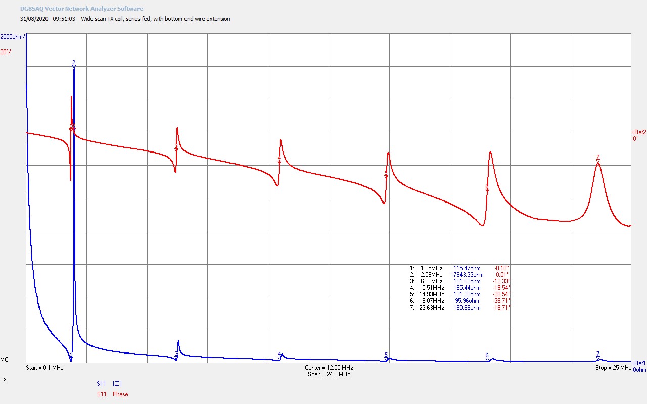
Fig 1.1. Shows a wide frequency scan up to 25Mc for the series fed secondary coil only, and with the bottom-end of the coil connected to a 2m wire extension to lower the impedance at the bottom-end, and hence ensure a λ/4 resonant mode. The fundamental resonant frequency ƒSS (secondary – series) of the secondary at marker M1 is at 1.95Mc in the 160m amateur band as per the cylindrical coil design. ƒSS corresponds to the transverse λ/4 series resonant mode for the coil, and is determined by the wire length of the secondary coil, and hence the overall inductance of the coil, combined with the coil self-capacitance. At ƒSS the series connected inductive reactance and capacitive reactance cancel out to leave the series resistance of the coil of 115.5Ω, with a phase Ø of ~ 0°. The series point of the secondary resonance can be clearly identified at ƒSS at the impedance minimum, which corresponds to the frequency at which an impedance phase change takes place, ƒSØ, and is generally characteristic of a series resonance. Above ƒS the second odd harmonic at 3λ/4 occurs at M3 at 6.29Mc, and with the higher order harmonics, 3rd, 4th etc. representing nλ/4 where n is an odd integer, and up to the 6th odd harmonic at M7 at ~ 23.63Mc. This wide frequency scan is typical of a high-Q, free-resonant, Tesla coil secondary, measured with minimal loading in a series-fed exciter circuit.
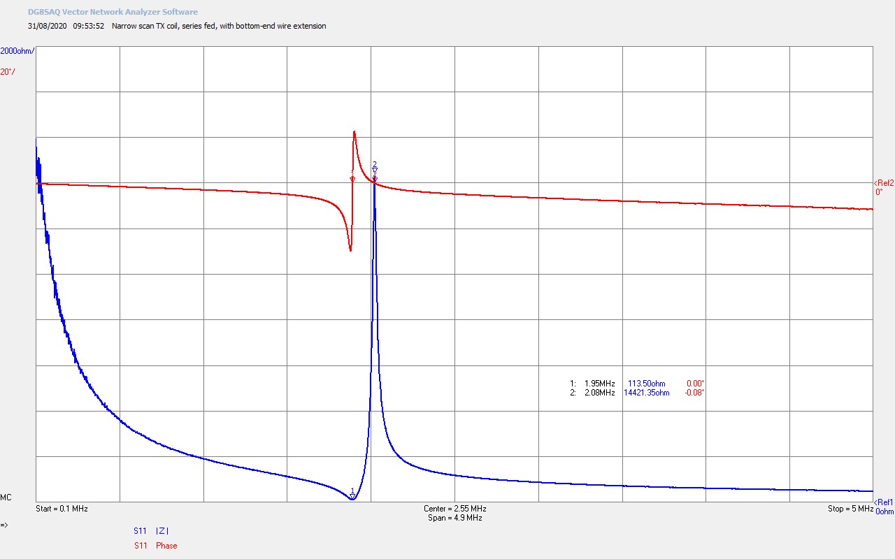
Fig 1.2. Here we see a narrower frequency scan up to 5Mc, which shows only the fundamental resonant mode of the secondary coil. It is here that we can start to get a better view of the true resonant nature of a Tesla coil secondary. The phase change, which is characteristic of a resonant circuit, is clearly defined marker at M1. This resonant circuit formed by the secondary has two modes associated with it. A series mode or point, at M1, where the impedance of the coil falls to a minimum, and a parallel mode or point at M2, where the impedance of the coil is maximum. This should not be interpreted as two separate resonant circuits with two independent resonant frequencies, as there are not two distinct resonant phase changes. A truly dual resonant circuit would be characterised by two resonant phase transitions which in principle move through 180° as the reactive impedance swings from inductive to capacitive and then back to inductive again.
In this cylindrical coil secondary, and in fact in all Tesla secondary coils that I have measured, a single resonant phase change is accompanied by a series mode, and a parallel mode. The impedance minimum of the series mode corresponds exactly to the resonant phase change, as can be seen in the scan at M1, where the series mode results from the inductance of the coil (λ/4 wire length), combined with the total self-capacitance of the coil to the surrounding medium, or in transmission line terms the self-capacitance to ground, combined with the total wire inductance. When the series inductive and capacitive reactance cancel, the series resistance is left at the minimum impedance point at M1, ƒSS = ƒSSØ = 1.95Mc.
In addition to the series mode, we also see here a parallel mode, which is not an independent resonant circuit, but an inter-dependent resonant mode formed within the secondary coil geometry. It is conjectured here that the mutual inter-turn inductance and the mutual inter-turn capacitance, that result from the geometry of the cylindrical coil, form a parallel resonant mode along the length of the secondary coil from top to bottom. It is further conjectured that this parallel mode is most directly related to coupling energy into the longitudinal magneto-dielectric (LMD) mode. The mutual inter-turn inductance combined with the mutual inter-turn capacitance form a distributed parallel mode at frequency ƒSP (secondary – parallel), which is inter-related to and inseparable from, the fundamental resonant frequency ƒSS defined by the phase change at M1 , and where ƒSP ≠ ƒSS.
At resonance, the distributed parallel mode inductive and capacitive reactance cancel out to leave a high resistance between the top and bottom-ends of the coil. This can be see in Fig. 1.2. at the parallel point marker M2 where Ø ~ 0°, so both the series and parallel points have a phase of zero, yielding a purely resistive secondary coil, minimum at the series point at ƒSS, and maximum at the parallel point at ƒSP. It is conjectured that this distributed parallel mode is directly responsible for the formation of the longitudinal mode in the secondary coil, and results directly in the formation of a high resistance longitudinal cavity between the top and bottom-ends of the coil. The inter-turn mutual inductance and capacitance are in the same plane along the length of the coil, and hence the dielectric and magnetic fields of induction, Ψ and Φ, form into the LMD mode, where a pressure wave-front, (or travelling wave), traverses backwards and forwards along the cavity.
The series mode at M1 corresponds to the secondary coil resistance minimum, and relates directly to the transverse mode of conduction between Ψ and Φ at ƒSS = 1.95Mc and series resistance RSS = 113.5Ω resistance. The parallel mode at M2 corresponds to the secondary coil resistance maximum, and is conjectured to relate directly to the longitudinal mode of conduction between Ψ and Φ at ƒSP = 2.08Mc and parallel resistance RSP = 14.4kΩ. Hence it is clear to see that the transverse and longitudinal modes resonate at different frequencies in a Tesla coil secondary.
It is suggested here, that the measured and observed phenomena in a Tesla coil secondary appears to result directly from the characteristics of the series and parallel modes, and hence the balance between the transverse and longitudinal modes, and the overall balance between the magnetic and dielectric fields of induction. This also has importance on which frequency or frequencies are used to drive the Tesla coil, and hence the generator type, and its tuning and matching to the coil system. I will take a more detailed look at this later in this post.
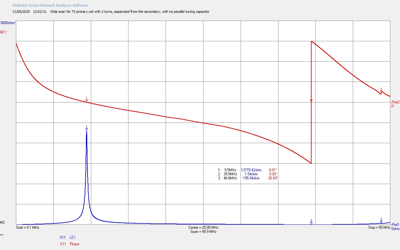
Fig 1.3. Shows the wide frequency scan up to 50Mc for the 2-turn primary on its own with no parallel connected tuning capacitor. The secondary has been moved completely away from the primary so that no coupling occurs between them, and hence the primary is not influenced by the resonant circuits in the secondary coil. The primary is parallel connected to the VNWA and forms a λ/2 resonator with series self-resonance occurring at ƒPS (primary – series) @ M2 = 39.5Mc and Ø ~ 0°, and where the phase change of the series resonant circuit corresponds with the impedance minimum, a series resistance RPS = 1.5Ω.
The primary coil resonant circuit also shows a series mode and a parallel mode similar in form to the secondary coil, but much more widely spread in frequency, and with the parallel mode below the series mode, rather than in the secondary where the parallel mode was above the series mode in frequency. The parallel mode ƒPP (primary – parallel) @ M1 = 9.5Mc and Ø ~ 0° has a parallel resistance RPP = 13.8kΩ.
The wide spacing between the series and parallel modes in the primary arises from the very significant imbalance between the inductive reactance of the coil and very small capacitive reactance, and results in a significant imbalance in the dielectric and magnetic fields of induction Ψ and Φ, where clearly Φ is strongly emphasised from the predominantly reactive impedance of the coil at frequencies below ƒPS.
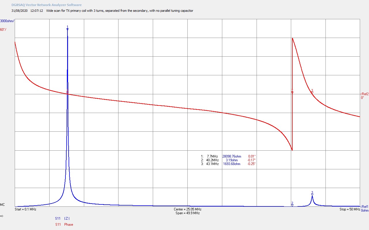
Fig 1.4. Here an extra turn has been added to the primary to make it 3 turns in total. There is a noticeable and interesting change in the both the series and parallel modes associated with the self-resonance of the primary. ƒPS the series mode at M2 has moved upwards from 39.5Mc to 40.2Mc, and with an expected increase in the series resistance RPS = 3.2Ω. Given that the extra turn has increased the inductive reactance we would expect ƒPS to have moved down in frequency. However, if we consider the series mode point carefully, the total end to end capacitance of the coil has reduced, as the ends of the λ/2 coil have moved further away from each other reducing the total self-capacitance of the coil. The combination in this increase in inductive reactance combined with a larger decrease in capacitive reactance has moved ƒPS to a higher frequency.
In contrast the parallel mode ƒPP @ M1 has moved down significantly from 9.5Mc to 7.7Mc, and accompanied with a significant doubling of parallel resistance RPP from 13.8kΩ to 28.1kΩ, giving the impression that the parallel mode has been strengthened or intensified as a result of adding an additional turn. In considering the possible origin of the parallel mode in the resonant circuit, this would appear to make sense, if the parallel mode results from the inter-turn mutual inductance and inter-turn mutual capacitance, we would have expected both of these to have increased by adding an additional turn, reducing the frequency ƒPP. The intensification of the parallel mode results in a stronger parallel resonance increasing the parallel resistance RPP, and it is conjectured increases the intensity of the longitudinal mode, and the amount of energy that can be coupled to this mode.
It can also be noted a small upper parallel mode has developed at 43.1Mc @ M3, Ø ~ 0°, and with a parallel resistance of 1.7kΩ. The emergence of another inter-connected mode shows the complexity of the distributed inter-action and inter-dependence of different vibrational modes in the coil.
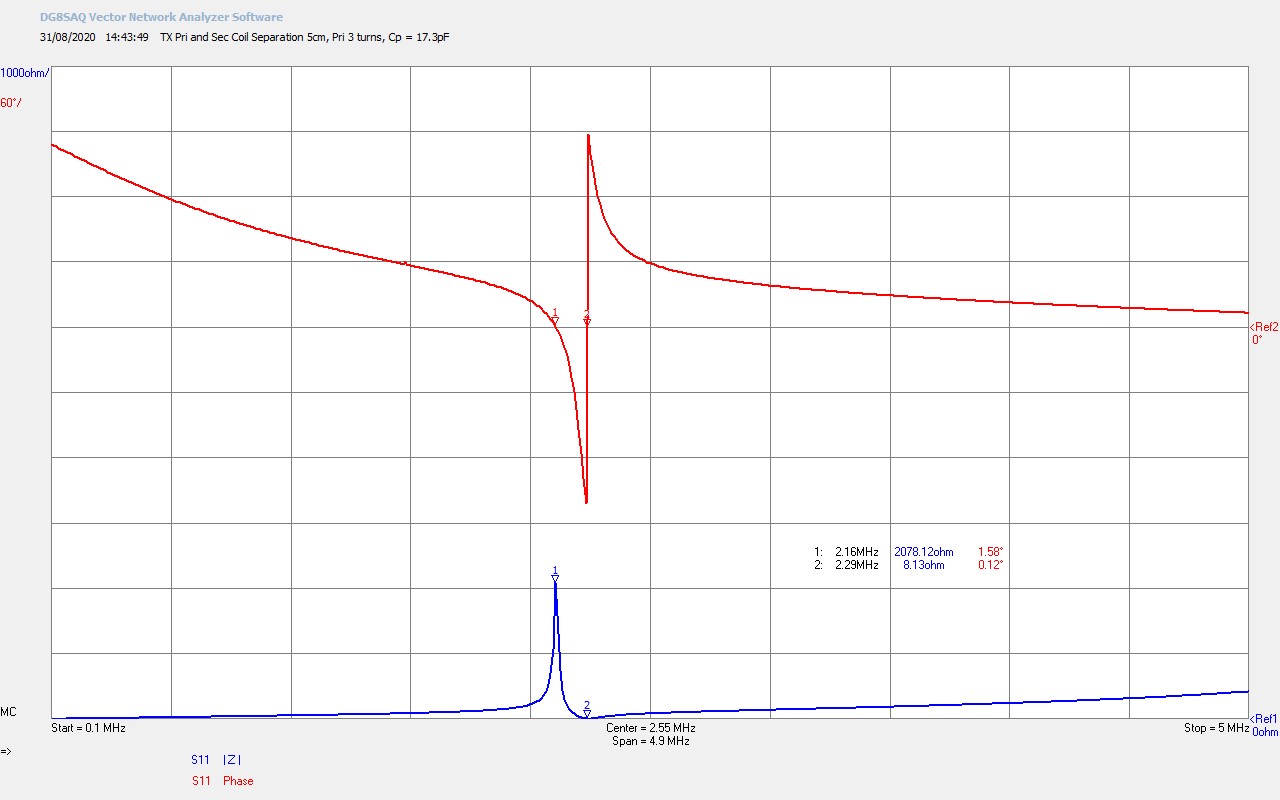
Fig 1.5. Now the primary coil and the secondary coil have been positioned in close proximity where the high-end (front) of the primary coil is 5cm behind the bottom-end (back) of the secondary coil. The primary is not interleaved inside the secondary, and the primary vacuum variable tuning capacitor has been connected to the primary but left full open at the minimum capacitance of CP = 17.3pF. Coupling coefficient is expected to be ~ 0.25, and will be covered in detail in my next post, Cylindrical Coil Transfer Impedance – TC and TMT Z21.
The primary and secondary coil now inter-act with each other, and the characteristics of the secondary coil are transformed back through into the primary circuit, where the input impedance Z11 is now reflective of the combined characteristics of the two coupled coils. The series resonant mode ƒCS (combined – series) which comes from the secondary coil has shifted up from 2.08Mc (free-resonator when unloaded series-fed), to 2.29Mc @ M2, Ø ~ 0°, and the series resistance RCS has been transformed down from 113.5Ω to 8.1Ω, a step-down impedance ratio of ~ 14:1.
The parallel resonant mode has gone through a particularly interesting transformation, and one that is key to understanding the inter-action between two coupled coils in a Tesla coil arrangement. It was conjectured that the parallel mode results from the inter-turn mutual inductance and capacitance in the coil geometry, producing a parallel resonator at a frequency different from the series mode. This occurs in both the primary and secondary coils that are now coupled, which means the parallel modes in both coils will inter-act and impact on each other.
This will change the parallel mode in both coils, and in this case the pressure of the higher frequency parallel mode from the primary ƒPP, has pushed the parallel mode from the secondary ƒSP down below the series mode. Where ƒSP > ƒSS for the uncoupled secondary coil, ƒSP < ƒSS when coupled to the primary. This is actually an extension of two inter-acting resonant circuits, which when coupled generate beat frequencies, which leads to frequency splitting, where both frequencies are shifted away from each other. As the coupling increases the splitting increases and the frequency span between ƒSP and ƒPP would increase. When the coupling reduces to 0, ƒSP and ƒPP can be at the same frequency, with no splitting. In this case ƒSP has moved to 2.16Mc @ M1 and below ƒSS @ M2. The parallel resistance RCP has been transformed down from 28.1kΩ to 2.1kΩ, a step-down impedance ratio of ~ 14:1, the same as for the series mode.
Another important implication of inter-active parallel modes is that the longitudinal cavity in the secondary can also extend to the primary circuit. So energy coupled into the parallel mode in the primary can be transferred directly into the secondary parallel mode and into the longitudinal cavity. This mechanism, along with energy transfer between the modes that occurs through constructive and destructive interference in the secondary cavity, allows the longitudinal mode to be pumped and driven by the tuning arrangement of the parallel modes in the primary.
This also establishes the requirement for tuning to an optimal balanced impedance match for the parallel modes, in order to transfer maximum power to the longitudinal mode in the cavity. Optimal operating conditions appear to arise from matching the generator for maximum power transfer to the transverse series mode frequency ƒSS, whilst balancing RSP = RPP for maximum transfer to the longitudinal mode. This will be looked at in more detail later in this post on generator tuning and matching, and is also an area that warrants considerable further research and investigation.
It is conjectured here that the optimal operating point corresponds to the best balance between the dielectric and magnetic fields of induction within the system, extending from the generator, through the primary circuit, through to the secondary circuit, and then continuous into the load or transmission medium circuit. Maintaining optimum balance between Ψ and Φ across the entire TC or TMT system will yield the highest transference of electric power efficiency, whilst providing the very best balanced equilibrium as a departure point, for the study of non-linear transient phenomena resulting from displacement.
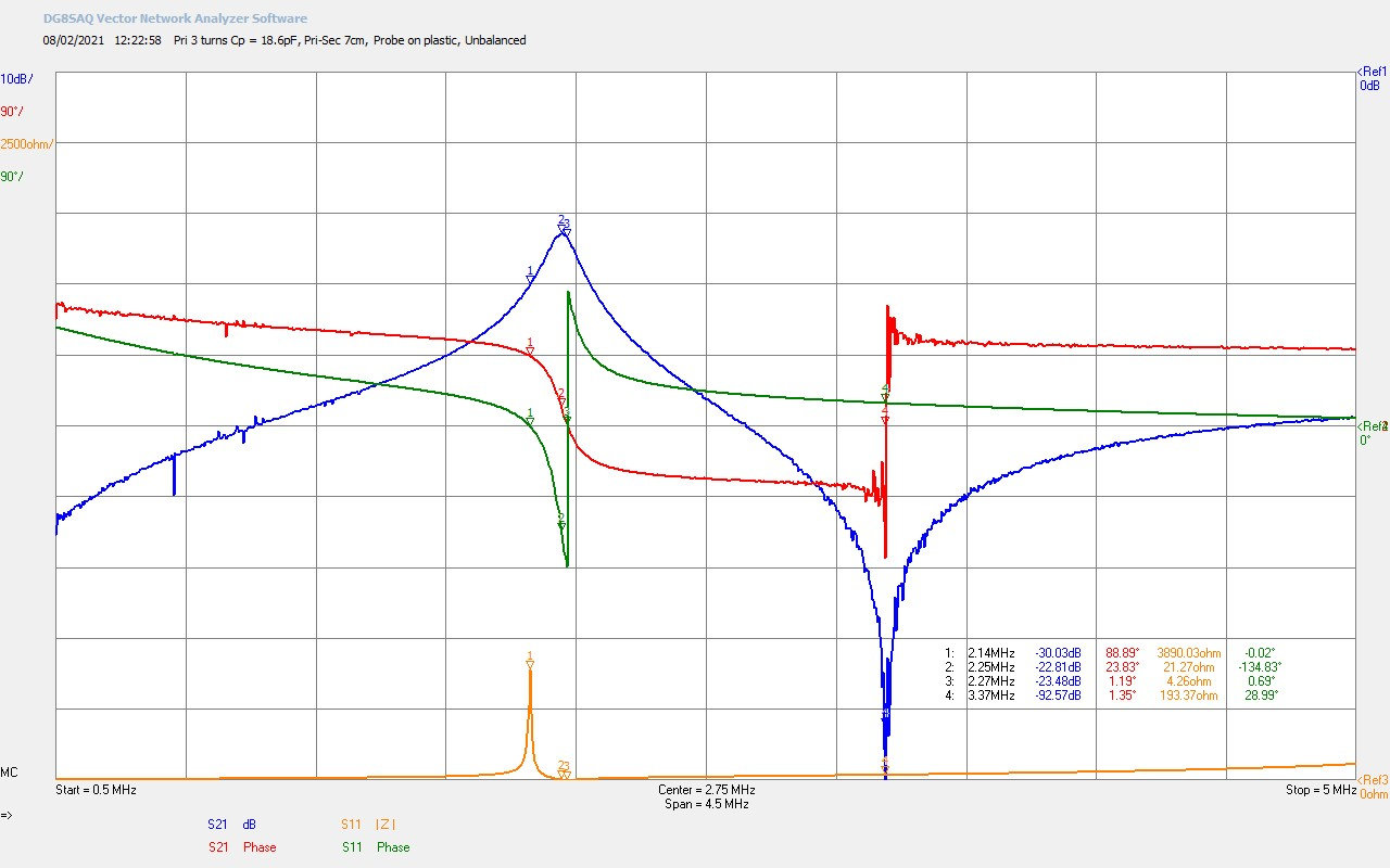
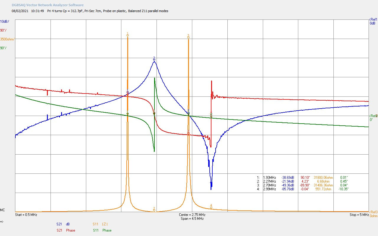
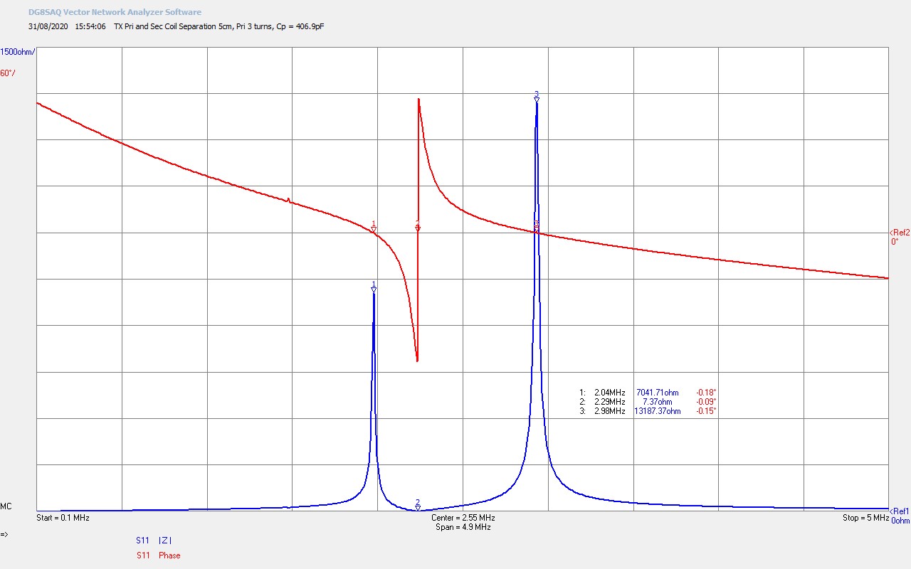
Fig 1.6. Here the primary variable vacuum capacitor has been adjusted to increase the primary capacitance CP = 406.9pF. As can be seen in the videos, the effect of increasing the tuning/loading capacitance in the primary circuit is to shift down ƒPP, (primary parallel mode frequency). It can be seen that CP has been adjusted to bring ƒPP into the scope of the secondary fundamental resonator modes. This also has the effect of pushing ƒSP down further away from ƒSS. In this way the characteristic TC input impedance result is obtained, and consists of three fundamental points:
1. One series mode from the secondary ƒSS = ƒO , the fundamental resonant frequency of the TC, where the 180° phase change occurs, (unwrapped phase).
2. One parallel mode from the secondary. When ƒPP > ƒSS, the lower parallel mode frequency of the TC, ƒL = ƒSP from the secondary.
3. One parallel mode from the primary. When ƒPP > ƒSS, the upper parallel mode frequency of the TC, ƒU = ƒPP from the primary.
The adjustment of CP makes large changes to ƒL and ƒU, whilst ƒO remains relatively constant. ƒO as previously described, is predominantly determined by the wire length of the secondary coil, and hence the overall inductance of the coil, combined with the coil self-capacitance. This does not significantly change with adjustments to CP, and therefore the resonant circuit phase change frequency remains unchanged at 2.29Mc (ref. fig. 1.5). The series mode resistance minimum RCS at ƒO is slightly influenced by the two parallel modes, and hence RCS has reduced from 8.1Ω (ref. fig. 1.5) to 7.4Ω.
It can be seen here that the upper parallel mode resistance RU = 13.2kΩ is both higher and dominant over that of RL = 7.0kΩ, and any direct generator match to the parallel mode, via for example a vacuum tube feedback oscillator, will oscillate stably at the upper frequency, ƒU. This will be considered in more detail later in this post as part of generator matching.
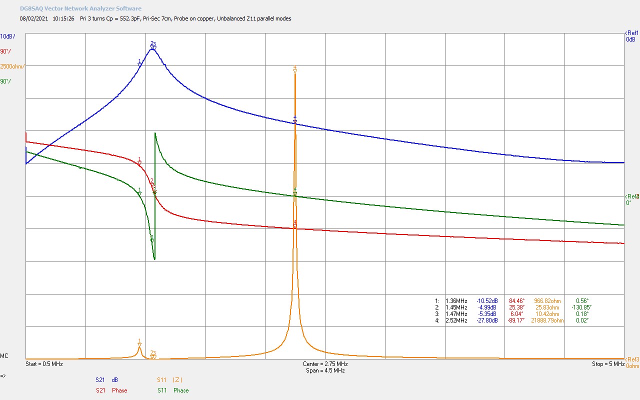
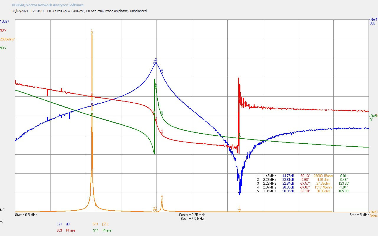
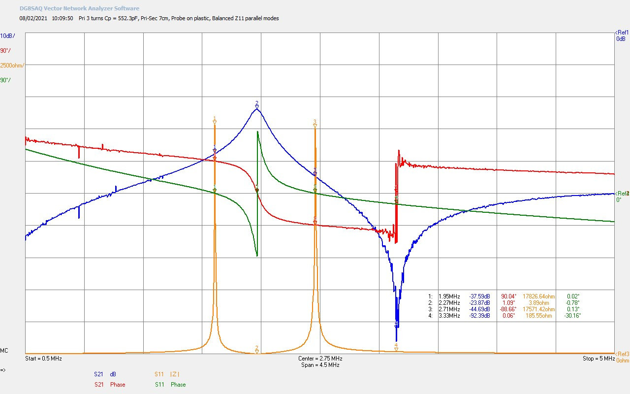
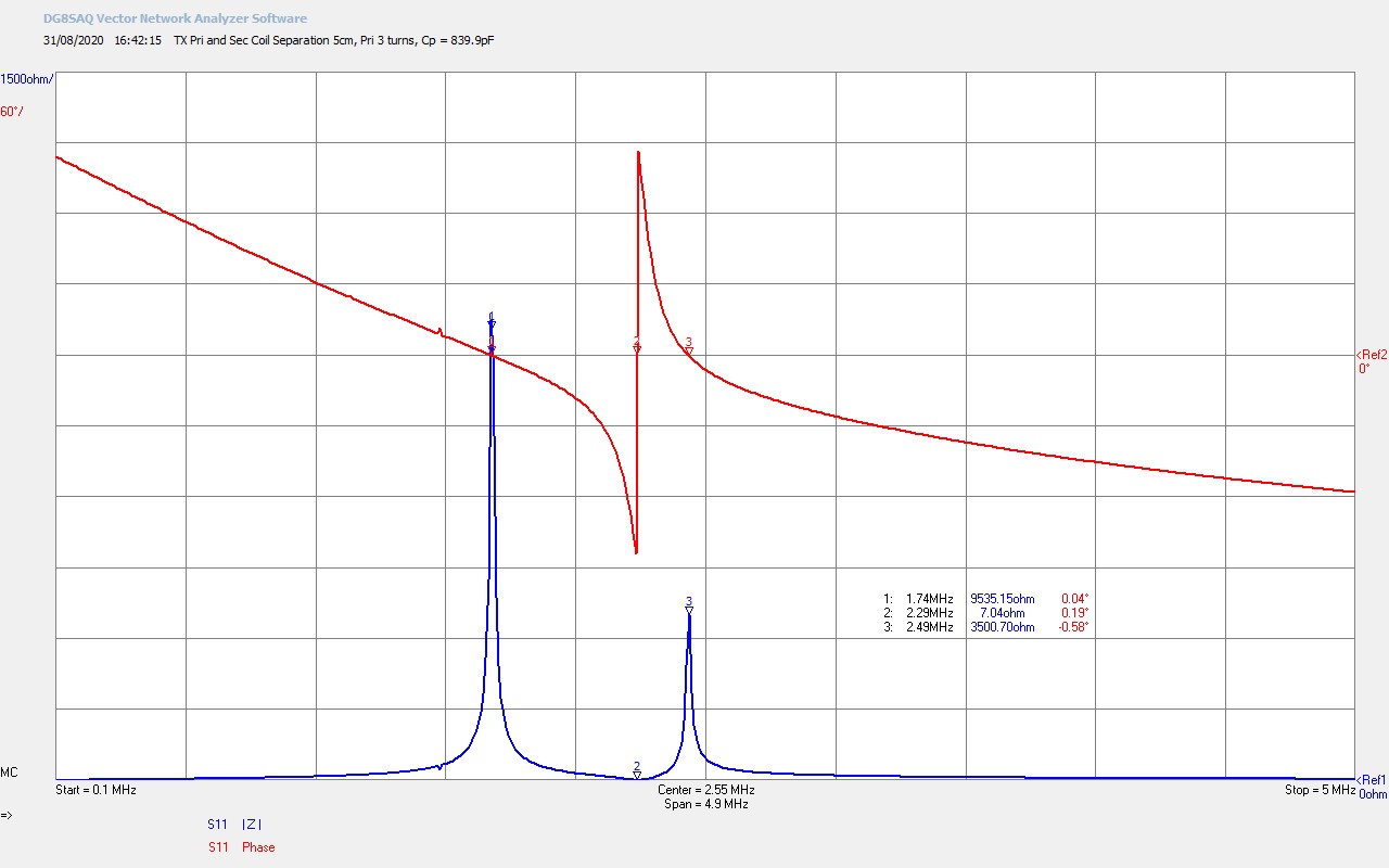
Fig 1.7. Shows the effect of adjusting the variable vacuum capacitor to increase the primary capacitance CP = 839.9pF. Here the ƒPP has moved through and is at a lower frequency than ƒSS. The three characteristic TC input impedance points are now:
1. One series mode from the secondary ƒSS = ƒO , the fundamental resonant frequency of the TC, where the 180° phase change occurs, (unwrapped phase).
2. One parallel mode from the primary. When ƒPP < ƒSS, the lower parallel mode frequency of the TC, ƒL = ƒPP from the primary.
3. One parallel mode from the secondary. When ƒPP < ƒSS, the upper parallel mode frequency of the TC, ƒU = ƒSP from the secondary.
In other words the parallel mode points (2 and 3) have now reversed, so that the primary point ƒPP dominates at the lower frequency, and the secondary primary point ƒSP is diminishing at the upper frequency. It can be seen here that the lower parallel mode resistance RL = 9.9kΩ is both higher and dominant over that of RU = 3.5kΩ, and any direct generator match to the parallel mode, via a vacuum tube feedback oscillator, will oscillate stably at the lower frequency, ƒL.
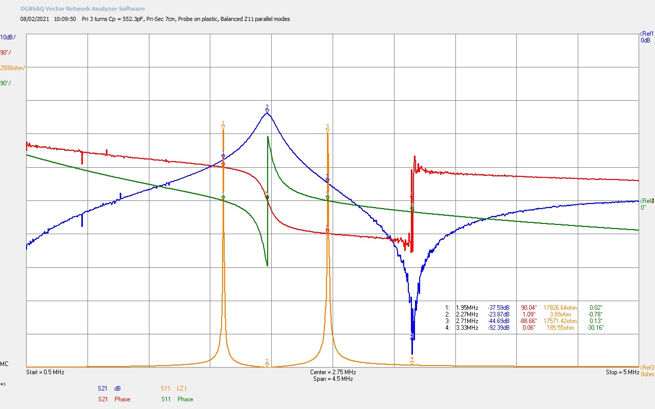
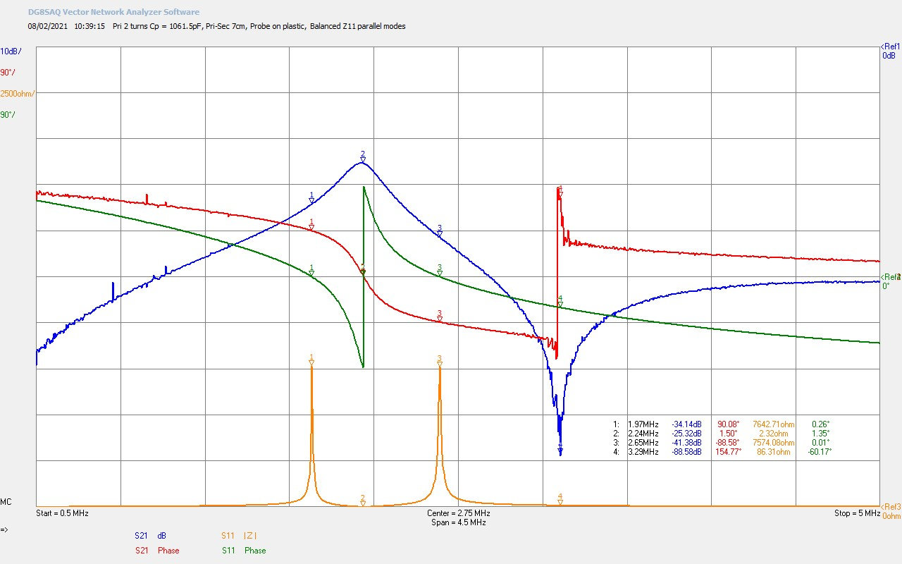
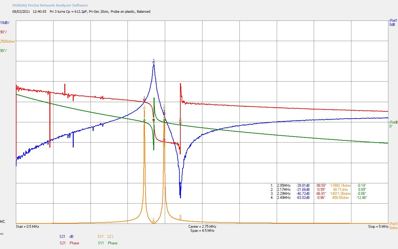
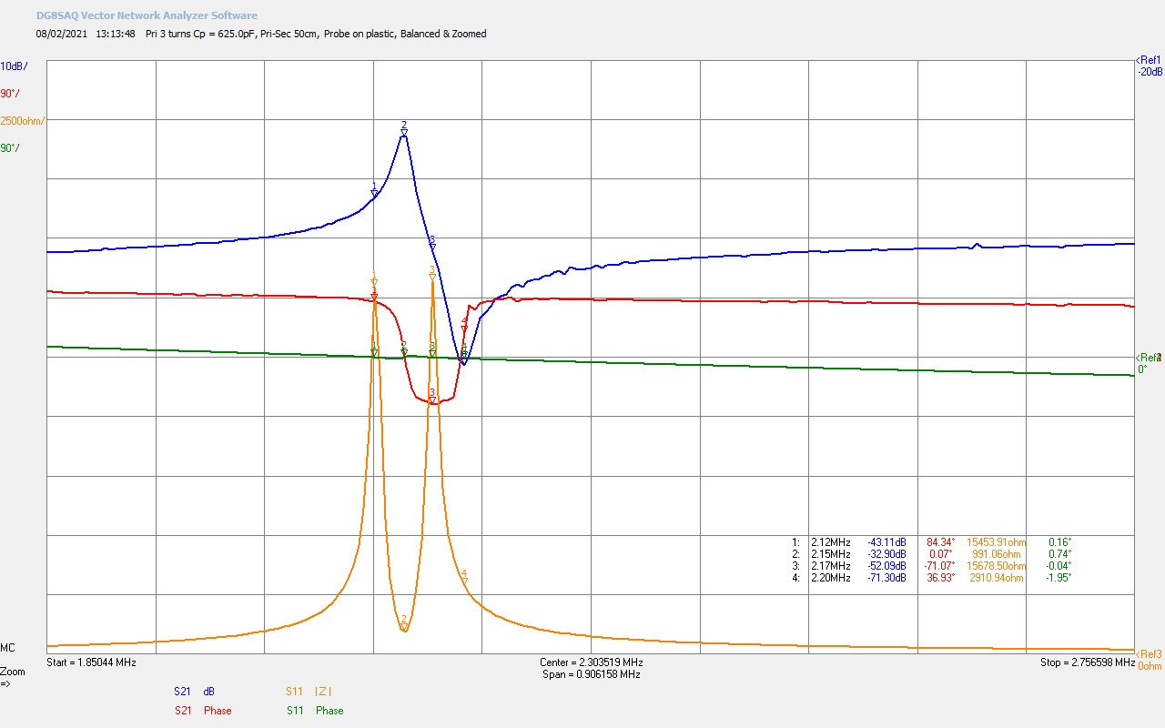
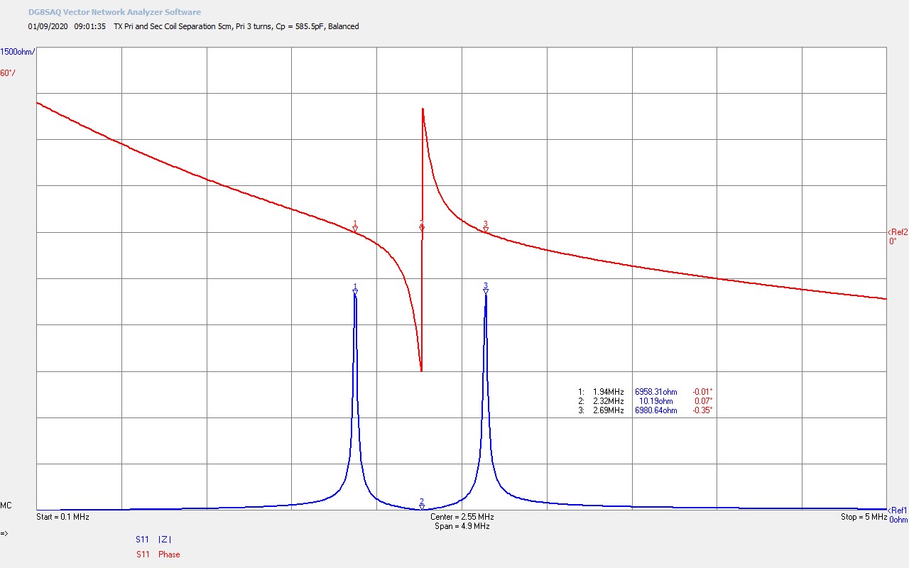
Fig 1.8. Here the primary tuning capacitor has been adjusted to balance the magnitude of the upper and lower parallel modes, CP = 585.5pF. This condition arises when the parallel mode from the primary is at the same frequency as the parallel mode from the secondary, ƒPP = ƒSP, and if the primary and secondary where uncoupled from each other completely (k = 0), and individually measured, then the parallel mode could be observed at the same frequency in both coils. This can be seen in the video where the secondary is finally moved out of coupling range of the primary, and the twin parallel modes collapse together to leave just a single parallel mode from the primary.
This point of tuning appears to be an optimal operating point when working with experiments on the transference of electric power, efficiency in power transfer can be measured to be a maximum across the system, and in TMT systems with suitable and designed coil geometry the LMD mode is well established, with a clear null in the centre of the single wire transmission medium. This operating point is not suitable when driving the system with a vacuum tube feedback oscillator as the frequency will flip unstably between the upper and lower parallel mode frequencies, as neither is dominant in this state of tune. At this operating point it is better to use a frequency controlled generator such as a linear power amplifier, or a spark gap generator with a tuned tank circuit.
It is conjectured here that this balanced and tuned impedance condition establishes the best balance between the dielectric and magnetic fields of induction across the system, extending from the generator, through the primary circuit, through to the secondary circuit, and then continuous into the load or transmission medium circuit. With a correctly matched generator for its type, maximum power can be transferred from the source to the load, and the LMD mode is at its greatest intensity in the cavity of the TMT system. The primary and secondary parallel modes are equal magnitude facilitating maximum power to be coupled and transferred into this mode of vibration.
There are also distinct differences in the observed characteristics and phenomena based on the type of generator used when driving this balanced operating condition. Generator types that produce a wide band excitation e.g. a spark gap or impulse generator can supply energy to all three coupled modes simultaneously, whereas a single frequency oscillator or linear amplifier will couple at one of the three modes, relying on mixing and cross-mode coupling to excite the other modes. This will be looked at in more detail later in this post.
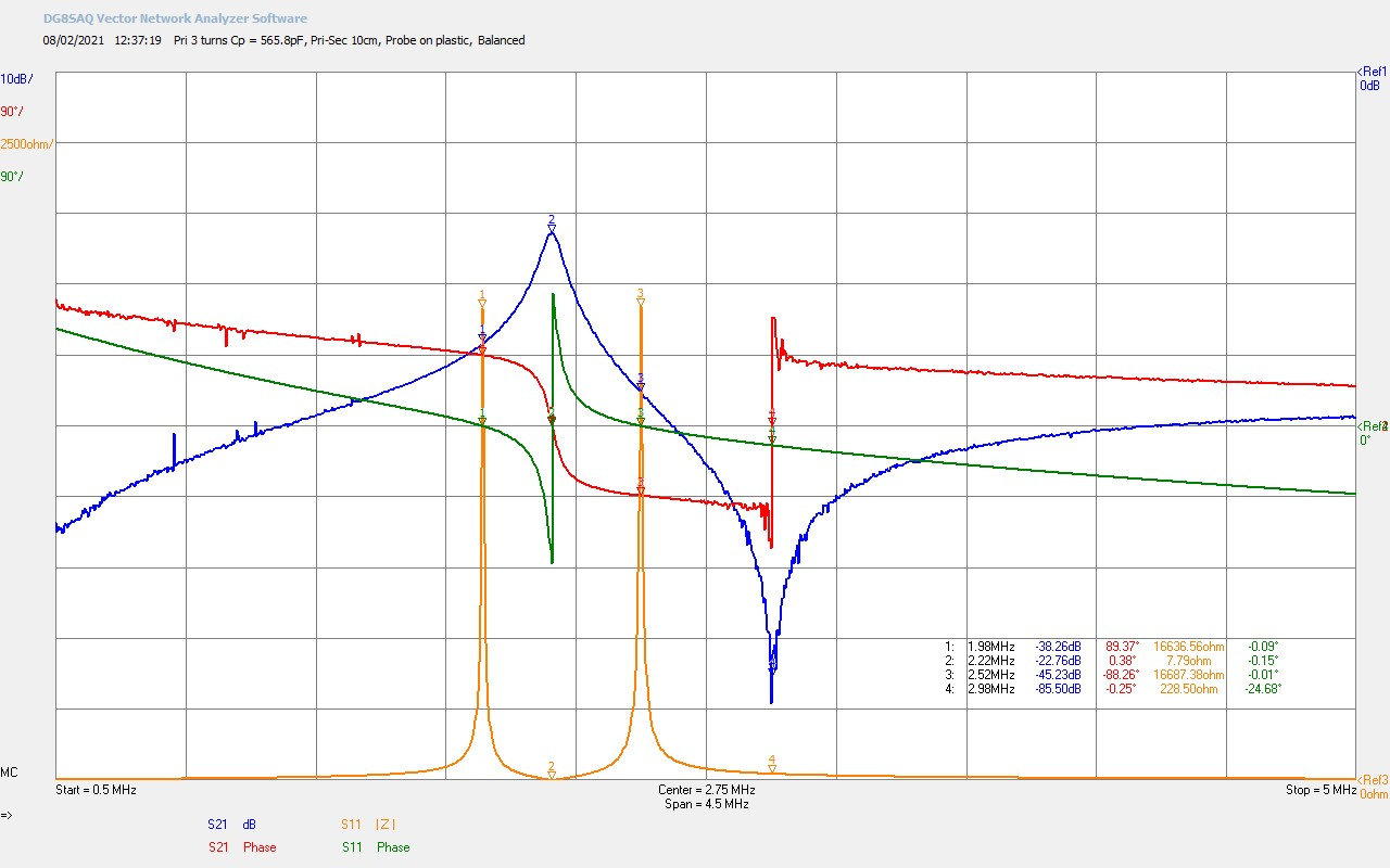
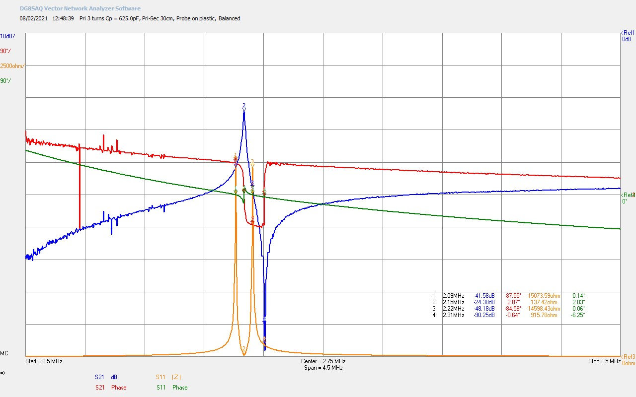
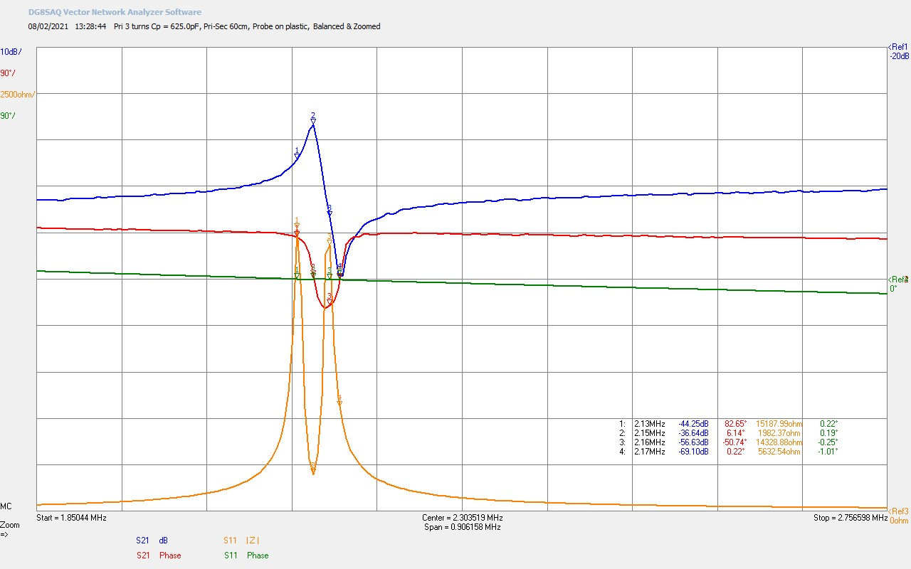
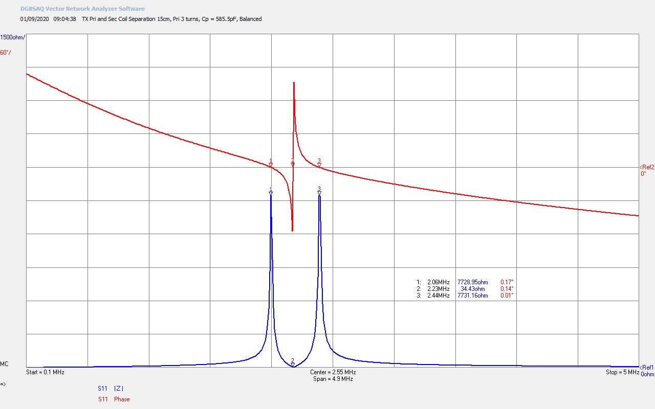
Fig 1.9. Shows the effect of reducing the coupling between the primary and secondary by increasing the distance between the on-axis coils to 15cm. The balanced tuning point has been maintained without readjusting the tuning capacitor at CP = 585.5pF. It can be seen that the two parallel modes at M1 and M3, either side of the series resonant mode at M2, have moved towards each other, narrowing the frequency gap between them. The series mode resistance RS = 34.3Ω at M2 has started to increase as the secondary resonance starts to move to a point where it will be out of coupling range of the primary. Coupling at this distance where k <~ 0.1 is not efficient for most experiments involving Tesla coils or for TMT systems. Empirically I have observed in my research that a coupling coefficient k between ~ 0.2 – 0.3 appears to yield optimal results, balancing power transfer, phenomena, and tuning, based on type of experiment, generator, and coil geometry used.
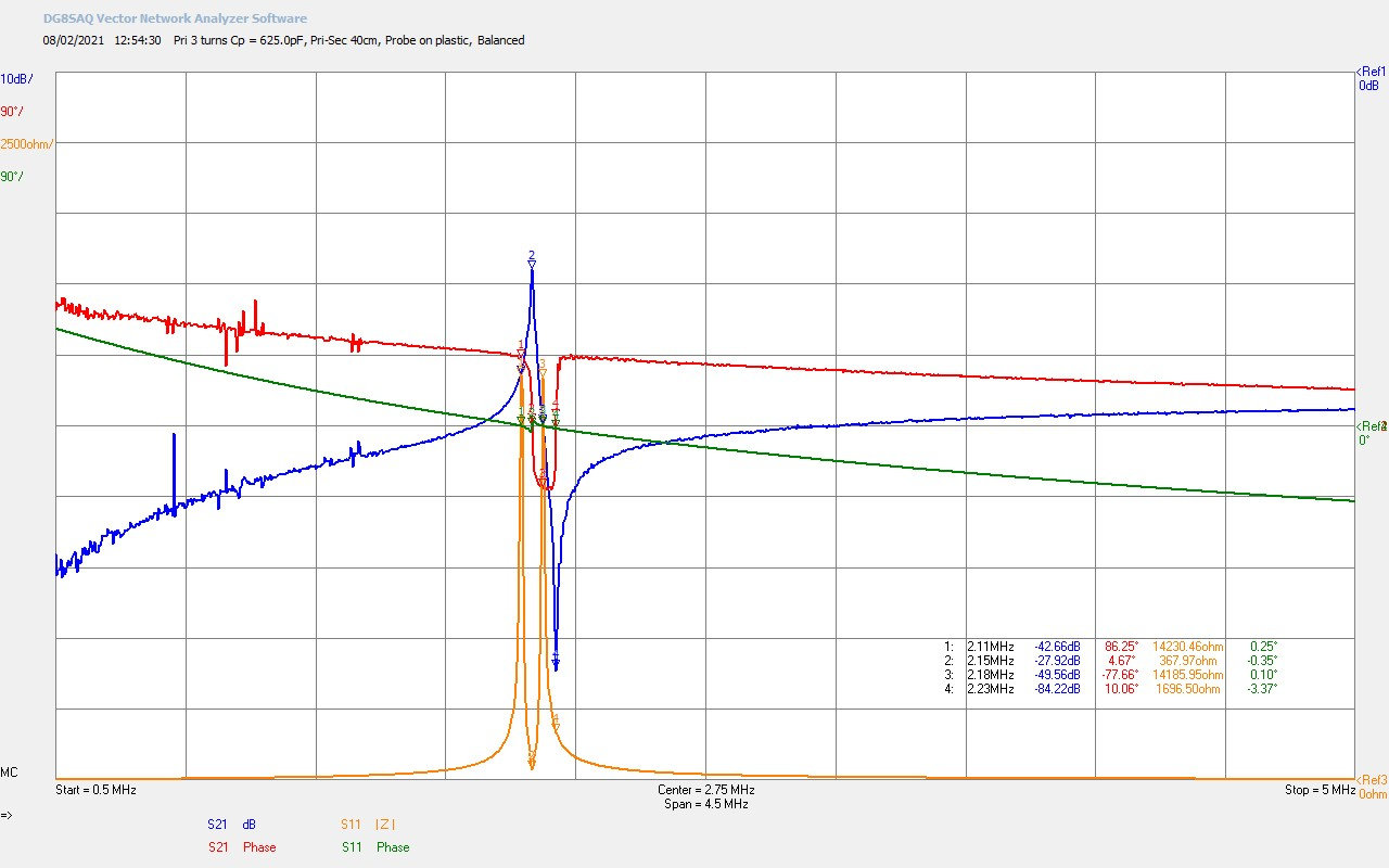
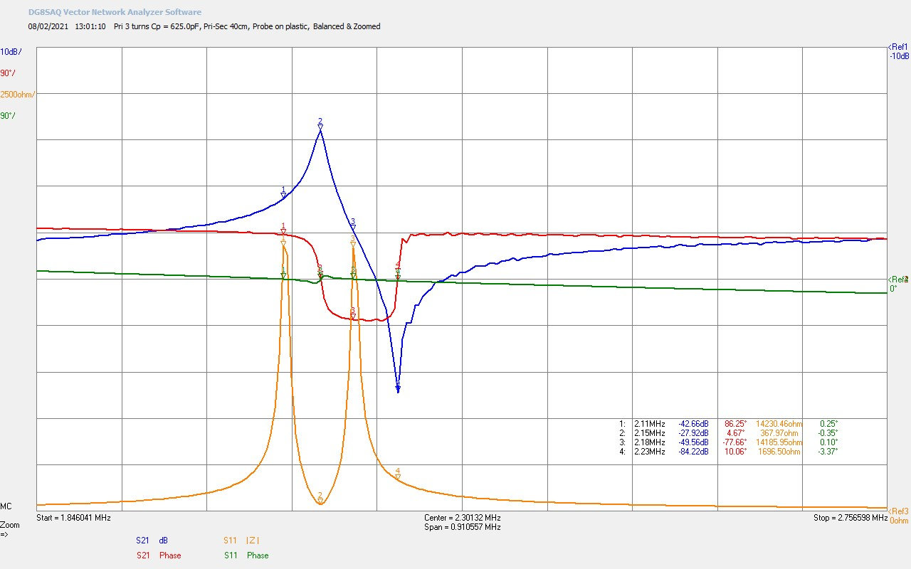
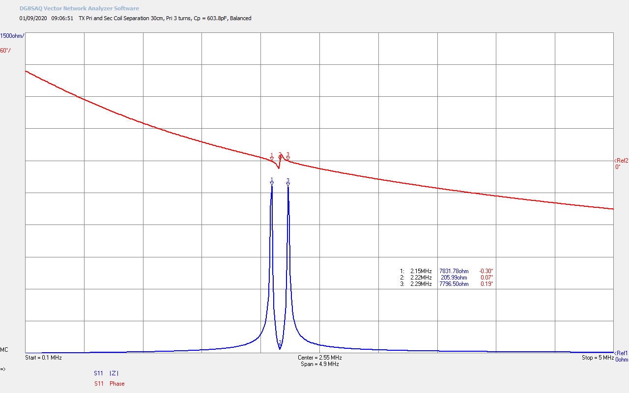
Fig 1.10. Here the distance between the primary and secondary has been increased to 30cm, and the coupling reduced to a very low level K <~ 0.05. In order to maintain the balance between the two parallel modes the primary tuning capacitor has been adjusted slightly to CP = 603.8pF. The parallel modes have collapsed further towards each other, and with further reduction in coupling the secondary will no-longer be coupled to the primary, and only a single parallel mode will remain from the primary coil, as can be seen in the video. The series resonant mode from the secondary is also diminishing, the phase change has become very small, and the series resistance RS has risen to 206Ω.
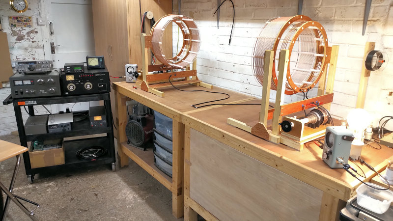
Figures 2 below show the key Z11 impedance measurements that were presented in the videos for two cylindrical Tesla coils combined into a TMT system, where the transmitter and receiver secondary coils are bottom-end connected with a single wire transmission medium.
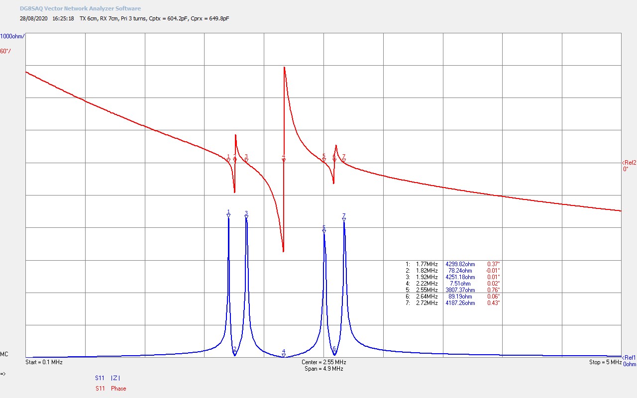
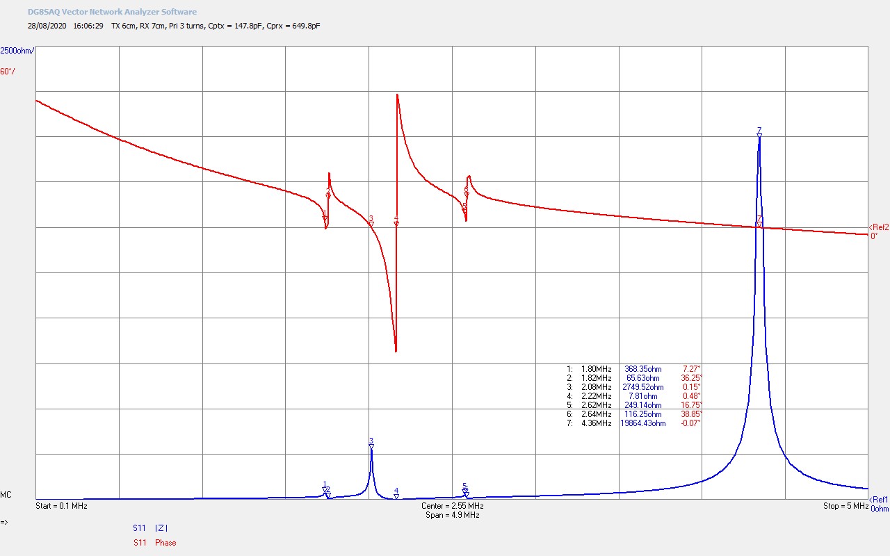
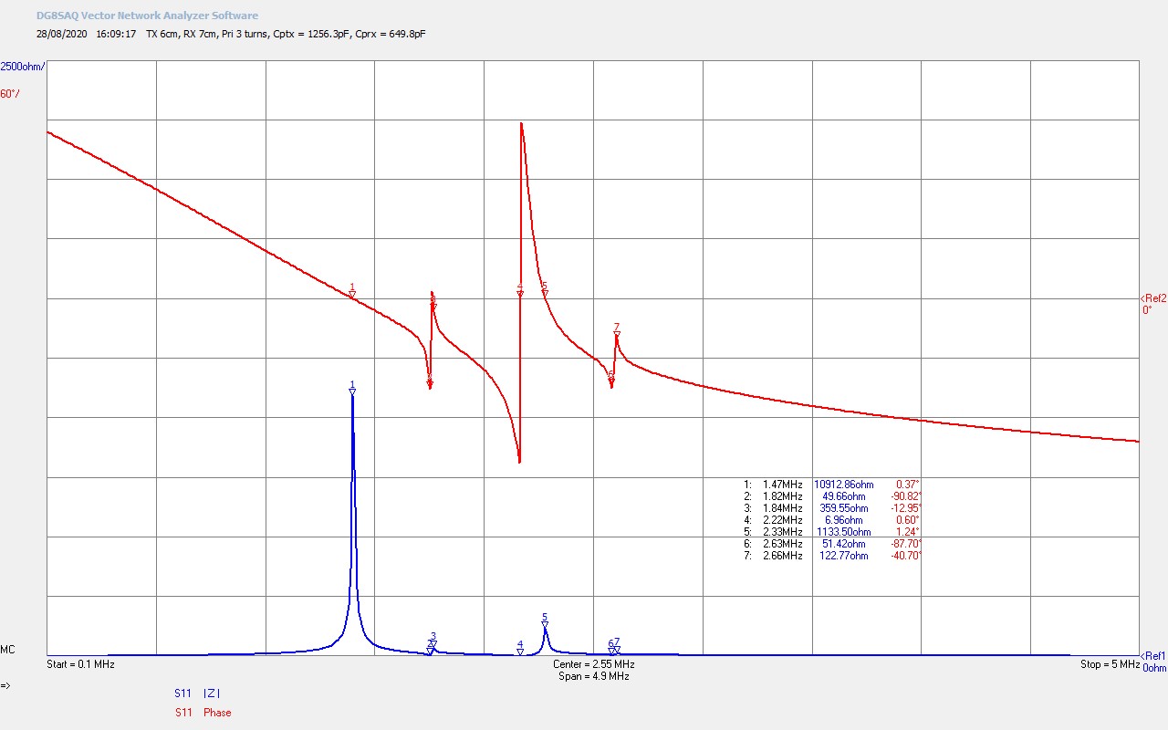
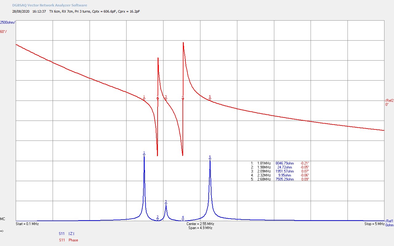
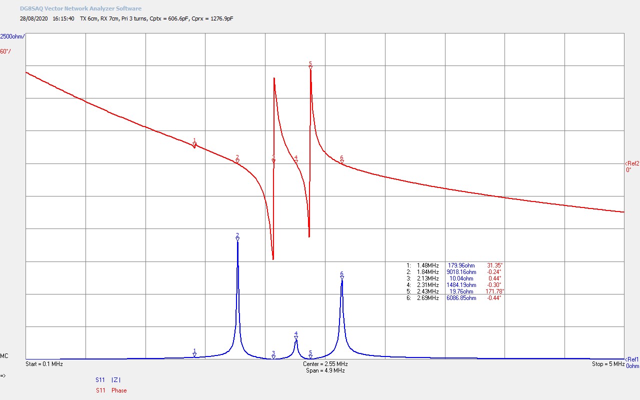
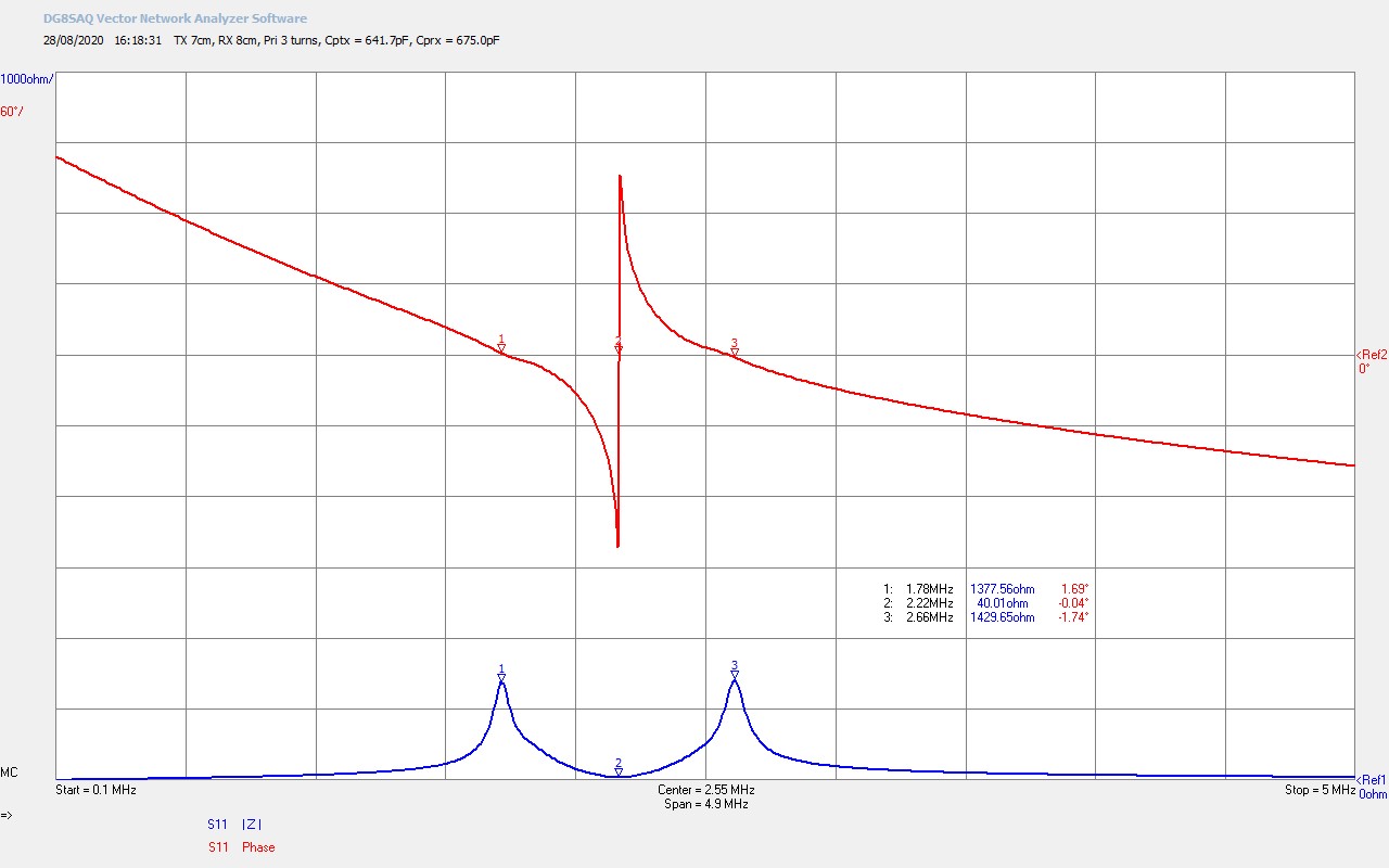


Fig 2.1. The TMT system measured here is two high-Q cylindrical Tesla coils, joined by a single wire transmission medium, in the near to close mid-field region. The separating distance between the TX and RX secondary coils in this case is 1.5m ~ 3 x the secondary diameter, which puts both coils well outside the region for direct magnetic field induction. The coil systems are counter-wound, the TX wound clockwise from the front, and the RX counter-clockwise from the front, which forms a reciprocal cavity between the two coil systems.
If the single wire is removed from either coil the impedance characteristics revert to that shown for the TX coil in fig. 1.6 – 1.8, the position in frequency of the three characteristic TC input impedance points being dependent on the tuning of the TX primary tuning capacitor CP. This confirms that there is no direct magnetic induction field coupling between the two coil systems in this measurement, and the TX and RX coils are not behaving as a conventional air-cored transformer. Inter-action between the two coils is only via the single wire transmission medium, and the overall input impedance at the TX coil primary reflects the combined resonant circuits and modes from both the TX and RX Tesla coils.
It can be seen immediately from the impedance scan that the individual TC characteristics of the TX and the RX have been combined, and that the upper and lower parallel modes have both split into two, revealing 4 parallel modes in total, 2 from the TX coil, and 2 from the RX coil. This splitting has occurred in the same way as for the individual TC, in that two coupled modes cannot resonate at the same frequency, they cause beat frequencies together and hence frequency split, where the split distance is based on the strength of the coupling between the two modes. In the balanced case shown here M1 and M5 originate from the TX coil, and M3 and M7 originate from the RX coil.
The central series mode resonance at M4 has only shifted very slightly from 2.29Mc (ref. fig. 1.6 for the TX), to 2.22Mc for the TX and RX combined, which indicates that the total wire length of the series resonant circuit remains approximately constant, with two counter-wound secondary coils of equal wire length connected together by a single wire. The transformed down series resistance present in the primary of the TX @ ƒO, RS4 = 7.5Ω, and is the lowest drive resistance of the overall TMT system characteristics. An interesting feature of combining the two coils is that the series resonant mode has also split to yield two resonant phase changes at M2 and M6, where the series resistance RS2 and RS6 are an order of magnitude higher than the RS4 at 78.2Ω and 89.2Ω respectively.
The TMT has been adjusted to be in reasonable balance so that the parallel mode resistance is equal, by adjusting the TX tuning capacitor CPTX = 604.2pF and the coupled distance, and the RX tuning capacitor CPRX = 649.8pF and the coupled distance. The very high-Q of the TX and RX resonators make this balanced adjustment very sensitive and very fine adjustments to each of the four tuning elements is required, as demonstrated in the video experiment. Tuning of this system becomes easier when a resistive load is added to the output of the primary of the receiver, which reduces the Q, and makes adjustment less sensitive. Empirically in my research, this balanced tuned position shown here appears to yield the highest efficiency in experiments on the transference of electric power. There are multiple possible generator matching points to this TMT impedance characteristic, which depend on both the type of generator being used, and the type of experiment being undertaken.
A summary of the seven key mode points, which are all series or parallel modes, and where the input impedance at each point is a pure resistance (Ø ~ 0°), is as follows:
M1 (1.77Mc, 4.3kΩ) – Lowest parallel mode from the TX secondary.
M2 (1.82Mc, 78.2Ω) – Lowest series mode from the TX secondary.
M3 (1.92Mc, 4.3kΩ) – 2nd parallel mode from the RX secondary.
M4 (2.22Mc, 7.5Ω) – Fundamental series mode from the TX – RX reciprocal wire length, ƒO. Generator match point for highest efficiency in transference of electric power between the generator and the receiver load.
M5 (2.55Mc, 3.8kΩ) – 3rd parallel mode from the TX primary.
M6 (2.64Mc, 89.2kΩ) – Highest series mode from the RX secondary.
M7 (2.72Mc, 4.2kΩ) – Highest parallel mode from the RX primary.
Parallel modes at M1, M3, M5, and M7 are best driven and explored with a tracking feedback power oscillator, whereas series modes at M2, M4, and M6 are suitable drive points for an impedance matched fixed frequency oscillator, linear amplifier, or tank tuned spark gap or impulse generator. More detail on this in the next section.
Fig 2.2. Shows the imbalance caused by reducing considerably the transmitter capacitance CPTX = 147.8pF. The parallel modes from the TX primary have shifted right up in frequency and become very dominant, whilst causing the parallel modes from the two secondary coils to become very suppressed. The fundamental series mode resonance remains unchanged, with some small shifts to the outer series modes. This is not in any way a desirable state of tune for operating the TMT system, but shown here to illustrate the effect of large imbalances in the primary tuning at the transmitter end.
Fig 2.3. Shows the imbalance caused by now increasing to maximum the transmitter capacitance CPTX = 1256.3pF. Here the lower parallel modes dominate with the upper suppressed. Again, this is not in any way a desirable state of tune for operating the TMT system.
Fig 2.4. Here we see an important change in all the characteristics of the TMT system from reactive loading at the receiver end. This has been caused by reducing to minimum CPRX = 16.2pF, but could also occur from increasing CPRX to maximum, or by the introduction of a significant reactive load to the output of the primary. Indeed, even adding a 500W incandescent load which has both series resistance and inductive reactance to the receiver output will cause parallel modes in the receiver to be suppressed or significantly reduced, the balance between the TX and RX to become skewed, and the series resonance modes in the transmitter and receiver to become separated into two distinct minima at M2 and M4.
ƒO at 2.32Mc at the upper series modes is still the optimum match point to gain the lowest transformed series resistance within the primary circuit RS4 = 9.95Ω, although driving at M2 @ 1.98Mc RS2 = 24.7Ω is still perfectly possible, and may in this case be preferred as M2 is directly within the 160m amateur band. This means that most filtered amateur transceiver and linear amplifier equipment will have maximum power gain in the designed band. Operating outside the designed band with commercial and unmodified equipment often produces restrictions on power due to out-of-band filters. Matching to this characteristic on the parallel modes is still possible using the vacuum tube series feedback oscillator, or other suitable generator specifically matched to the high impedance of this mode.
Overall by significantly loading the output of the TMT either reactively or resistively will significantly change the balanced and reciprocal nature of the TMT cavity, skewing the impedance characteristics towards the transmitter, and requiring a change in matching according to loading changes. When driving from a matched and selected frequency generator, such as a linear amplifier, it is worth bearing this in mind that sudden and rapid load changes can cause significant mismatch issues at the generator end.
Fig 2.5. Shows the other end of reactive loading at the receiver end of the TMT by maximising the capacitive loading on the primary. The general characteristics are very similar to fig. 2.4, although the series modes are now shifted upwards and reversed, so ƒO is now at the lower series mode at M3, 2.13Mc, and RS3 = 10.04Ω . Again both series and parallel modes can be matched and driven according to experimental requirements.
Fig 2.6. Here a 100W incandescent resistive load has been added to the receiver output of the TMT. The reactive load is not sufficient to cause the shift in characteristics seen in figs. 2.5 and 2.6, but rather here the resistive load has reduced the Q of the system, causing the upper and lower parallel modes to merge together with a reduced resistance at the peaks of the modes. This it typical for a TMT with a resistive load and actually makes it considerably easier to balance and tune. Generator drive matching can readily be achieved at all three points, the parallel modes at M1 and M3, and the fundamental series mode at M2. For most experiments in the transference of electric power this would be the typical impedance characteristics, with a resistive load at the output of the receiver primary, and/or a resistive load in the single wire transmission medium for tuning and power load-split tests.
Tesla Coil System Input Impedance and Generator Matching
Generator matching to a Tesla coil and TMT system is a most important and yet often unreported or overlooked area of the overall system design. Correct impedance matching between the generator and experimental system ensures optimal power transfer between the two, and hence maximises the available power to be delivered to the experiment and load. Matching also reduces energy loss through excessive dissipation in circuit elements, and reflected power from the experiment back to the generator, leading again to significant energy loss, and minimising possible damage to the generator, matching circuits, and tuning components.
TC and TMT systems, suitable for laboratory experiments, are usually designed to run from 10W – 10kW. As the power levels go up, and especially in the order of a few hundreds of watts and above, correct impedance matching becomes crucially important, as significant reflected and dissipated power can easily lead to discharges, excessive heating, and ultimately destructive permanent damage to circuit components and elements, as well as excessive over-heating and fire risks. In addition, matching plays a crucial role in driving a TC and TMT system at different operating points in its impedance characteristics, which in turn facilitates different types of electrical experiment, phenomena, observations, and measurements.
In this section we are going to take a more detailed look at how to match different types of generators to the cylindrical coil TC and TMT, and using the small signal input impedance characteristics Z11 measured previously in this post. The types of generators, matching, and operating conditions explored here are based on what I have investigated throughout my own research so far, and that I use in my own lab on a daily basis. Impedance matching is vast and detailed subject both theoretically and experimentally, for further reading and study of the subject area I recommend RF Design Basics by Fielding[2], and for the vacuum tube aspects, Valve Amplifiers Explained also by Fielding[3]. I will be focussing on the empirical and experimental aspects of matching a range of different generators directly to the cylindrical coil, at different operating points, and the advantages and limitations inherent within each approach.
Fig 1.8 shows the balanced tuned characteristics for a single cylindrical Tesla coil, and the three fundamental serial and parallel modes present in a primary tuned coil. One of the most basic measurements of resonant frequency for a Tesla coil is to attach a signal generator or other variable oscillator directly to the input of the primary coil, and then measure the output, using a probe or wire in close proximity to the high-end of the secondary, and attached to the input of an oscilloscope. By adjusting the input frequency it is easily possible to maximise the amplitude of the sine wave measured on the oscilloscope. It is important not to connect the oscilloscope probe directly to the high-end as this will load the secondary coil and change its frequency characteristics leading to a lower measured resonant frequency. Also magnification of the input needs to be considered, so that a small signal at the input e.g. 1VPP does not overload the input to the oscilloscope based on the voltage magnification of the TC.
When this method is used, maximising the amplitude of the secondary output signal yields point M2 on the Z11 characteristics of fig. 1.8, the fundamental series resonant frequency of the secondary, ƒO. Adjusting the signal generator around points M1 and M3, the parallel points, shows no discernible change in the oscilloscope output. In other words, the parallel points appear as though invisible to this basic measure of resonant frequency. This is not a limitation for matching certain types of generator to the coil, as in most cases the TC is to be driven directly at the transverse series resonant frequency, and this is all that matters. For example, in the case of a TC designed to maximise streamer discharge using a vacuum tube linear amplifier as the generator, (a VTTC or vacuum tube Tesla coil), and where from fig. 1.8, ƒO = 2.32Mc, and the primary resistance at this point RS = 10.2Ω, these are the only important details necessary to optimise the generator match, and transfer maximum power through to the secondary coil.
For more sophisticated experiments and exotic phenomena with Tesla coils, e.g. for transference of electric power in a TMT system, plasma discharge phenomena, or Tesla’s radiant energy and matter, the type of generator, how it is matched, and what operating points are chosen is most important. Due to the very high voltages and currents usually present in a Tesla coil, spark discharge and vacuum tube based generators tend to be far more robust and reliable over a wide range of operating conditions. Although I have designed, built, and operated different types of semiconductor based generators for use with Tesla coils, I do not generally use them in my research into the inner-workings of electricity.
Semiconductors do not go at all well together with high-voltage, or with rapidly changing impedance in a high-Q system where voltages can easily swing from low to very high, or with high reflection coefficients and large voltage standing wave ratios (VSWR), any of which can easily destroy semiconductors from over-voltage conditions very quickly. A good quality power vacuum tube is usually very tolerant to these types of changes in operating conditions and matching in a Tesla coil system, and therefore my generator of choice is usually vacuum tube based, or a well-built spark-gap or impulse generator, dependent on the type of experiment at hand.
The choice of type of generator for the type of experiment is also very important. Some generators produce controlled single frequency linear oscillations at high voltage, others produce bursts of oscillation, others disruptive discharges with very high currents, or high-current short duration impulses. Different phenomena, observations, and measurements will result from matching a particular type of generator output, to a specific type of experiment, with a specific type of coil geometry. What follows is an introduction and initial consideration of the major types of generator that I have used to power my research experiments, the type of experiments and phenomena they are best suited to, how best to setup the matching for this generator and system, and which operating points in the impedance characteristics yield the best results for the required operating conditions.
Vacuum Tube based Series Feedback Oscillator
The Vacuum Tube Generator (VTG) covered in a previous post, and which has been used to drive many experiments in my research so far, is primarily configured as a tuned plate class-C Armstrong oscillator, which derives automatic feedback from a pick-up coil placed close to the secondary coil. This arrangement of vacuum tube oscillator is ideal for driving a TC or TMT system at the resonant frequency parallel modes e.g. at points M1 or M3 in fig. 1.8. Positive feedback derived from the secondary coil via the pick-up coil, energises the grid circuit of the tubes, causing the anode circuit to oscillate. The great benefit of this feedback method is that as the parallel modes shift in frequency through tuning and coupling changes, the oscillator will track the parallel mode frequency change, providing a highly adjustable and versatile generator drive to these modes. The circuit diagram for the VTG and peripherals is shown in Figure 3 below, or click here to view the high-resolution version.

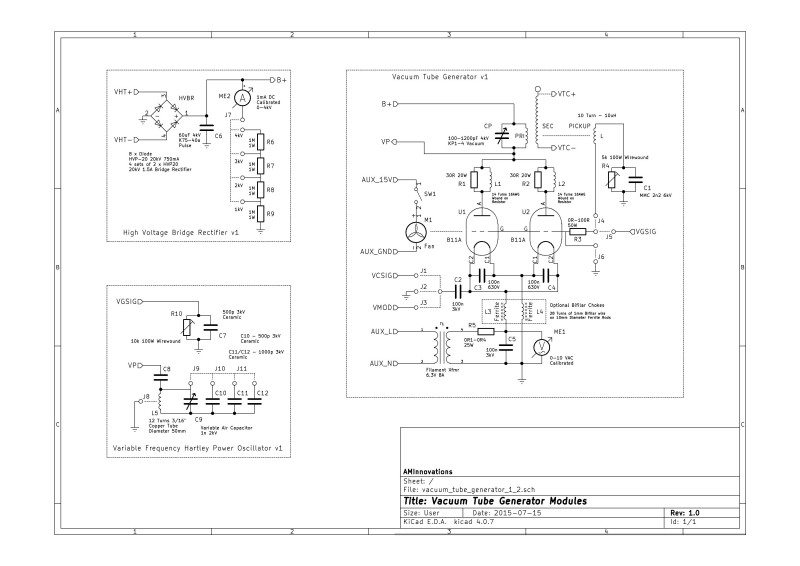
From the circuit diagram we can see that the primary tank circuit of the TC, consisting of the primary coil (PRI) and primary tuning capacitor (CP) in parallel, is in series with the vacuum tube plate circuit, and fed directly by the high-voltage plate supply B+. This arrangement makes the primary tank circuit the series load in the plate circuit of the oscillator. Fig 1.7 shows the tuning condition where the lower parallel mode frequency ƒL @ M1 has been arranged to be dominant where ƒL = 1.74Mc and RP = 9.5kΩ. At this tuning point and using the VTG as the generator, the system would be stably oscillating at 1.74Mc. The typical plate resistance of the 811A tube close to maximum operating ratings for an RF oscillator of VP = 1200V and IP = 150mA, is RA = 8kΩ. Two tubes in parallel will reduce the plate resistance to ~ 4kΩ, so the series plate circuit consists of the following. A resistive load from the TC tank circuit of 9.5kΩ, in series with the 811A tube resistance of 4kΩ.
At resonance the tank circuit is resistive only, with no reactive components, and so the tube oscillator sees a straight resistive load, where the actual load resistance is in the same order of magnitude as the plate resistance of the tubes. By adjusting B+ and the amount of grid feedback, (via grid storage resistor R4, and grid limit resistor R3), the combined plate resistance of the tubes can be adjusted to match the tank circuit parallel mode resistance where RA = RP. In this optimum matching condition, maximum power can be transferred from the generator to the parallel mode resonance of the TC. In practise this form of series feedback oscillator is very tolerant of the operating point, and can be adjusted over a wide tracking range of ƒL and ƒU, without any need to continuously adjust or tune the grid feedback. When the desired operating frequency has been established, the grid feedback can be adjusted slightly to match the plate resistance of the generator, to the actual load resistance of the TC primary tank circuit, and ensuring maximum power transfer at the desired operating frequency.
For this cylindrical coil design ƒL can be adjusted and driven stably in the range ~ 1.6Mc – 2.1Mc by adjusting CP. Energy is coupled to the secondary circuit through the lower parallel mode and directly into the longitudinal cavity of the TC or TMT system. When the operating point of the system is adjusted to Fig 1.6 the system is tuned for ƒU to be dominant, and the generator will track with frequency in the range ~ 2.5Mc – 4.0Mc. In the same way energy is coupled to the secondary circuit, although this time through the upper parallel mode. The range of tuning compatible with the series feedback oscillator appears to be ~ 500kc for ƒL and ~ 1500kc for ƒU.
This form of feedback oscillator is not suitable for driving the system at the series resonant mode at M2, ƒO = 2.29Mc. Here the impedance of the TC falls to the minimum resistance for the system RS = 7.4Ω, and represents only the series resistance of the secondary coil transformed down through the primary. When driven as the series load the voltage developed across the load is very small, with almost all of the plate supply B+ across the non-conducting, and hence non-oscillating, vacuum tubes. No power is transferred from the primary to the secondary and the primary tank circuit is not energised to oscillate.
The transition between driving the lower parallel mode at M1 and the upper parallel mode at M3 represents a region of significant instability for this type of generator. If CP is first adjusted to stably oscillate at ƒL, then by decreasing CP the generator will track the increasing frequency parallel point at M1, until it starts to become close to the balanced condition as shown in fig. 1.8. Around this point the oscillator will flip rapidly backwards and forwards between the ƒL and ƒU, and never stably oscillating at ƒO. If CP is still further increased then the system passes through this point of instability and stably settles oscillating at ƒU, which can continue up to 4Mc and even slightly above in the presented system. In practise it is possible to get this generator stably oscillating right at the top-end of the band for ƒL, or right at the bottom-end of the band for ƒU, and hence by close proximity couple considerable power to the series mode at M2. This is particularly the case when driving a resistive load in the single wire transmission medium, or at the output of the receiver primary, in a TMT system. This extra stability results from the reduction in Q of the overall system when loaded with a heavy resistive load, and is clearly demonstrated in the video experiments in Transference of electric power – Part 1.
Overall this form of generator provides an extremely flexible, tolerant, and robust way of experimenting with the parallel modes, and in some limited cases the series mode of a TC and TMT system. It is easy to setup, and a reasonable generator-to-experiment matching is inherent due to the high internal impedance characteristics of vacuum tubes. With grid feedback adjustments at a specific frequency this generator can be optimally matched to transfer maximum power from the generator to the TC system parallel modes, which in-turn enables a wide range of tunable experiments on the transference of electric power, dielectric charging effects, and some plasma phenomena. With non-linear transients, bursts, or impulses provided by SCR switching in the B+ supply, no B+ supply tank, or cathode switching and modulation, limited experiments on displacement, and radiant energy and matter are also possible.
Vacuum Tube or Semiconductor based Linear Amplifiers
This form of generator is best suited for exploring the series resonant modes of a TC and TMT system. It is completely adjustable in frequency and power from the exciter circuit, and does not rely on feedback from the secondary circuit. It can be tuned to any frequency in the impedance characteristics provided a suitable match can be established between the linear amplifier and the primary tank circuit, and hence the voltage standing wave ratio (VSWR) at the generator output is compatible with the drive characteristics of the power amplifier or exciter circuit or both. In practical terms the high resistance of the parallel modes is difficult to match to a linear amplifier and supply any amount of reasonable power > 100W.
For the series modes a very accurate and optimal match can be established between the generator and primary tank, and hence a lot of power can be transferred to the TC or TMT system at a single frequency. This generator type is by far the best for high-efficiency transference of electric power through a TMT system to a load in the receiver. Powers > 500W and up to 5kW can be readily transferred to the receiver load, where the transmission medium is only a single thin wire. With a high-efficiency designed and balanced coil geometry, such as a cylindrical coil TMT system, with or without an extra coil resonator, efficiencies in transference of electric power can be > 95%, and with careful tuning and balancing > 99%.
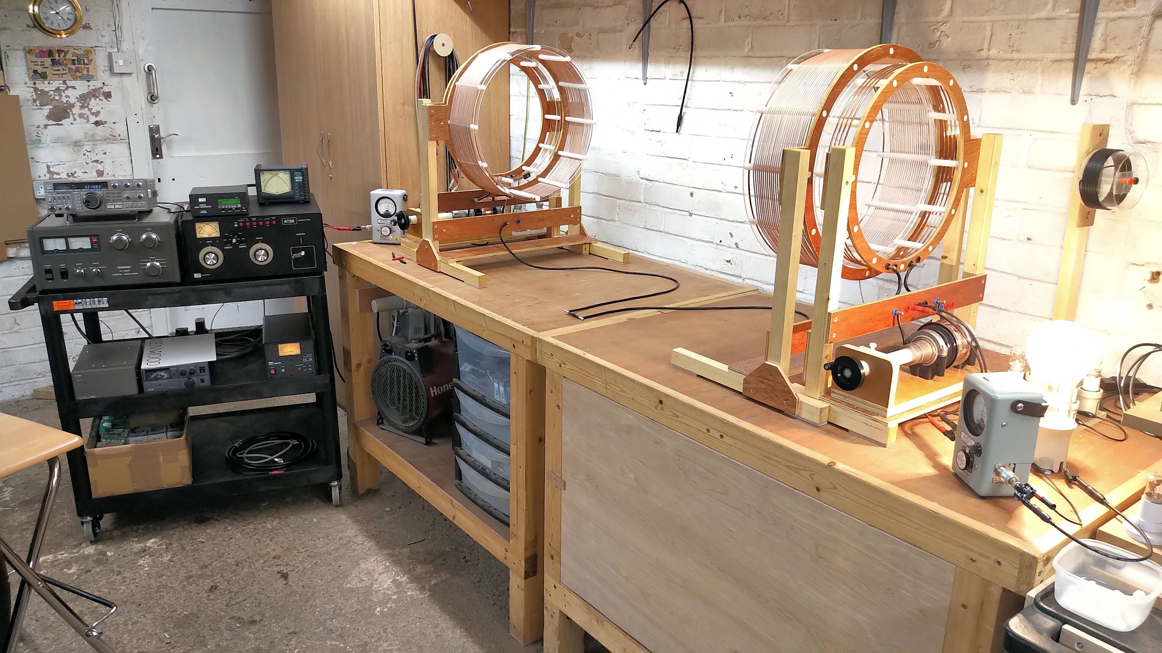
Figures 4 below show a linear amplifier generator setup which is capable of transferring up to 1kW from generator to load. This generator system is coupled to a cylindrical coil TMT system, and with a demonstrated transference of electric power efficiency of > 99%.
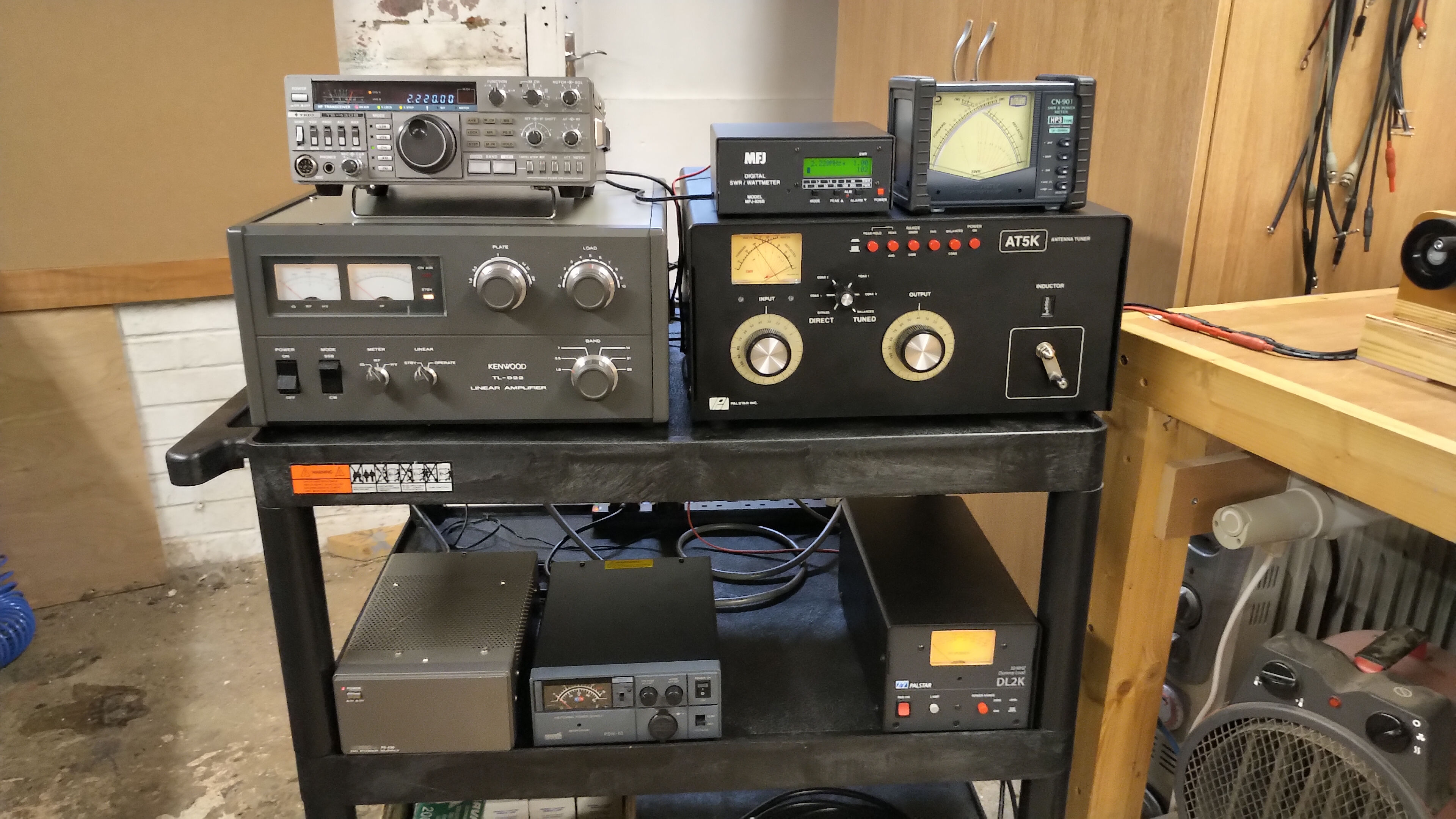
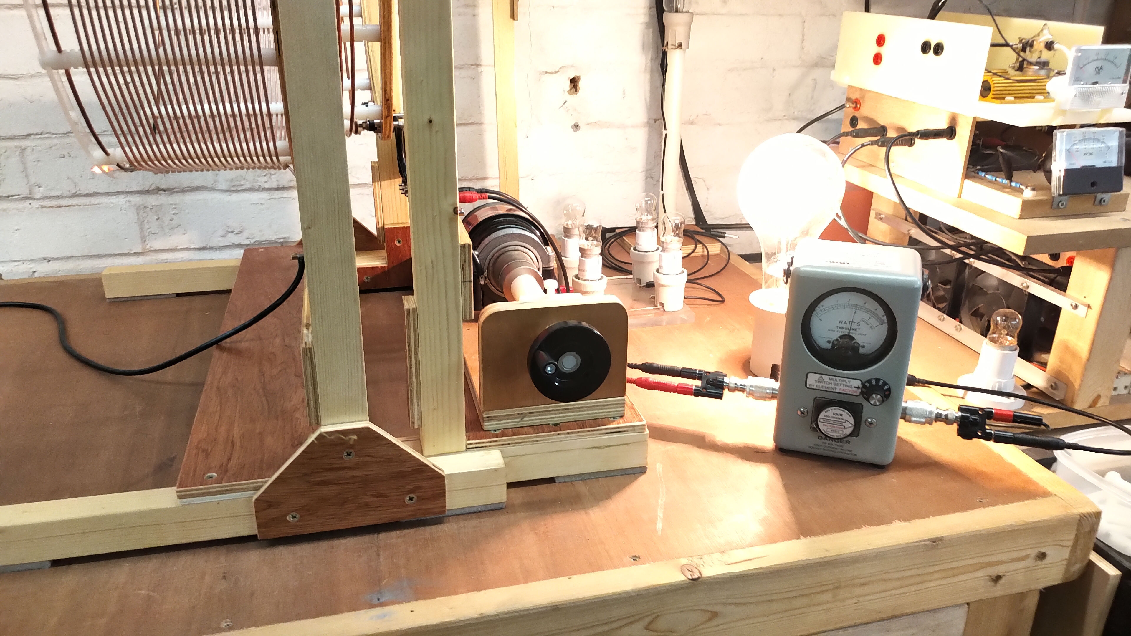
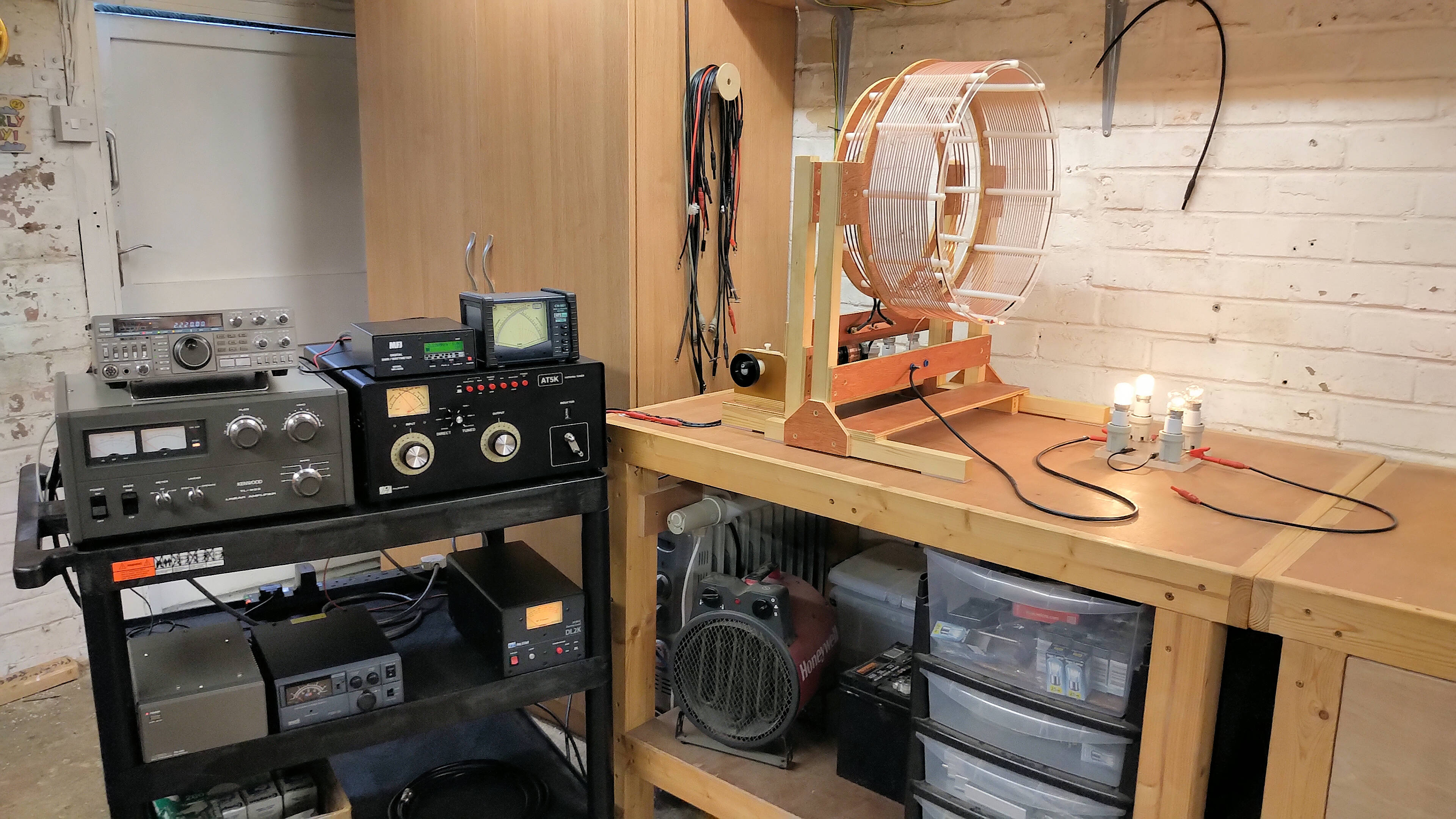


The system in fig. 4.1 consists of the following:
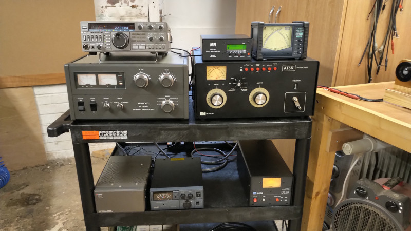
1. The exciter is a Kenwood Trio TS-430S 100W HF amateur radio transceiver. This era of transceiver has digital frequency synthesis, a semiconductor power driver, AM and FM modulation, and easily modified to extend its capabilities. In this case it has been modified to transmit on all frequencies across its tunable range, which makes it into a high-power, up to 100W, bench-top signal generator with modulation capabilities. Here it is set to 2.22Mc just above the 160m amateur radio band. The transceiver system is not connected to any radiating antennas, and hence will not cause out-of-band interference.
2. The exciter is connected directly to a Kenwood TL-922 1kW linear amplifier which is a vacuum tube based, (dual Eimac 3-500Z), HF power amplifier. This linear amplifier has π-network matching circuits on both input and output. Slightly out of band prevents running this linear amplifier at the full 1kW when in the fully matched condition, standing wave ratio (SWR) ~ 1, but can be de-tuned, (SWR <~ 2 ), to the TMT input impedance at the series mode resonance, to output almost 800W of power, and up to 1200W in very short bursts.
3. The output of the linear amplifier is connected through an MFJ-804D digital power and SWR meter to monitor the match at the output of the linear amplifier.
4. The output of the SWR meter is connected to a Palstar AT5K 5kW antenna tuner which handles the impedance transformation from the 50Ω output of the linear amplifier to the ~ 7.5Ω input resistance RS at the fundamental series resonant mode at M4 at 2.22Mc, Fig 2.1. The AT5K is a T-network matching unit, with input and output continuous variable capacitors, and a continuous variable roller inductor. This unit is capable of tuning a very wide output impedance to the 50Ω input required for safe and optimum performance of the linear amplifier.
5. The output of the AT5K can be switched to bypass which connects to a Palstar DL2K 2kW 50Ω dummy load which is used to initially tune the output of the linear amplifier for maximum power output at the exciter frequency. When this is completed the AT5K is switched back to balanced tuned output connected to the primary circuit of the transmitter cylindrical coil.
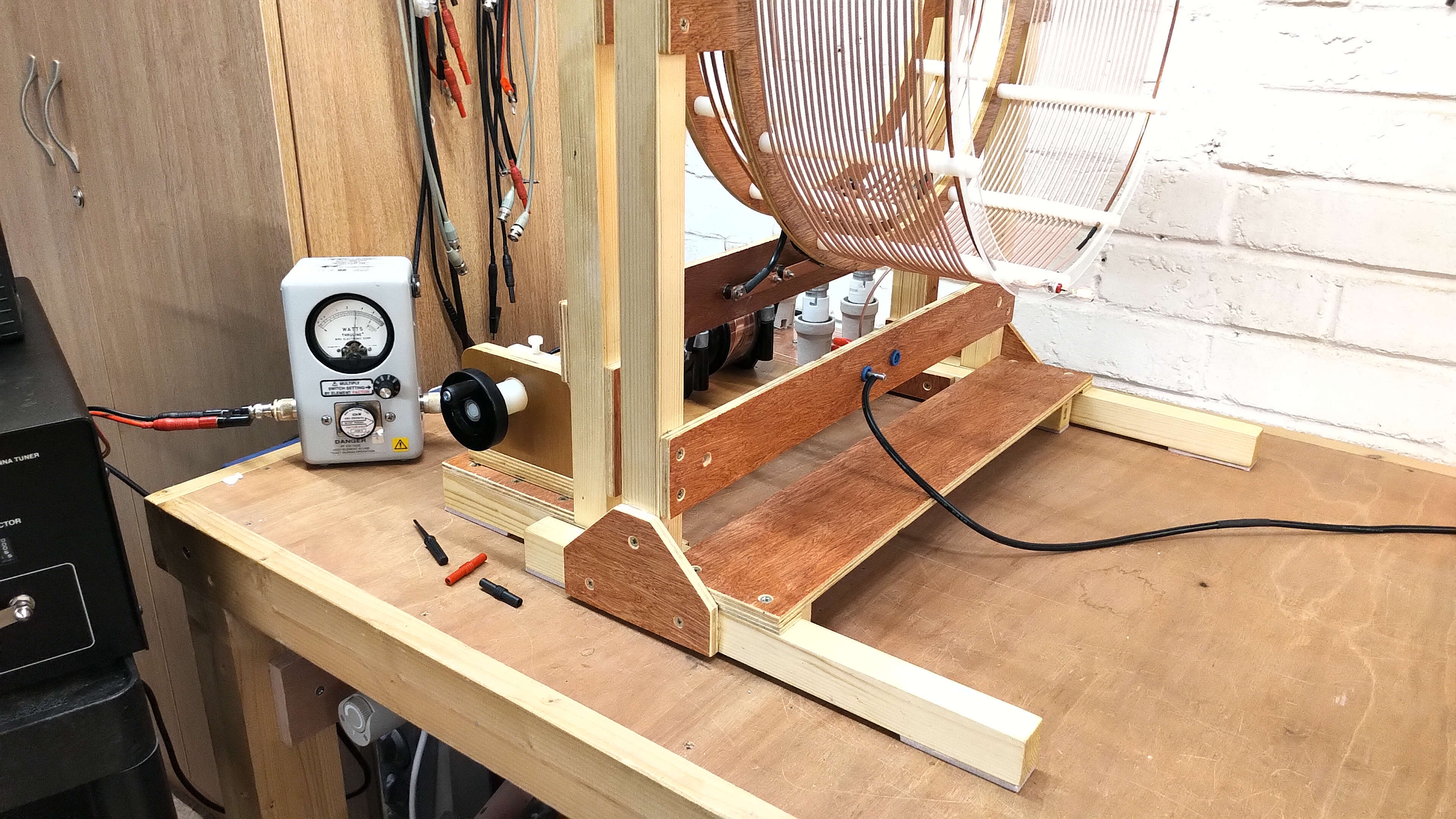
6. Between the output of the AT5K and primary coil is a Bird 4410A Thruline power meter with a 450kc – 2500kc 10kW slug, for measuring the real power actually supplied to the transmitter primary.
7. Between the output of the receiver primary circuit and the 500W incandescent lamp is a second Bird 4410A Thruline power meter with the same rated slug, for measuring the real power supplied from the receiver primary to the load.
8. Both Bird power meters are simultaneously calibrated on the same output power to ensure accurate aligned measurement, and then the transfer power efficiency of the TMT system can be directly measured, and in this experiment case was 98.5% at 380W real input power to the transmitter primary.
The pictures in figures 4 show the linear amplifier generator in high-efficiency transference of electric power experiment, between the TMT transmitter and receiver with a single wire transmission medium, to illuminate a 500W incandescent load in the receiver. The same generator was also used to power a single TC with single-wire power dissipation in a 100W incandescent load. This linear amplifier arrangement can drive the TMT system at all the series mode at M2, M4, and M6 (ref. Fig 2.1), when the output of the generator is carefully matched in order to keep the SWR at the power amplifier output <~2. With a load in the receiver, such as a 500W incandescent bulb, the Q of the TMT system is reduced considerably and the fundamental series mode at M2 (ref. Fig 2.6), becomes the optimum driving point.
In all cases the key to using this form of generator is to keep the SWR at the output of the power amplifier low enough, through careful matching of the input resistance at the required series resonant point. Flexible tuning during high-power operation is not really possible with this form of generator, since as the frequency is varied the linear amplifier tuning, and the AT5K antenna tuning, both need to be adjusted to keep the SWR at a low enough level for safe operation. In practise with this generator type, very high powers can be transferred from the source transmitter to the receiver load, at very high efficiencies, and through a single wire medium, provided the matching is kept very tight and accurate.
Semiconductor Based Switching Inverter
This type of generator is generally more suited to TCs operating at lower frequencies, 25kc – 1Mc, and switches a DC supply, typically the rectified and smoothed line supply, providing a 340V DC supply (UK). A full bridge inverter uses 4 power mosfet or IGBT semiconductor transistors to alternately switch the current through the primary coil in a froward and reverse direction. The switched currents can be very large which leads to a strong magnetic induction field coupling from primary to secondary. The primary circuit is generally not resonant (SSTC solid-state Tesla coil), and the inverter driver matches the frequency from feedback derived from the secondary coil, to match the inverter switching frequency to the fundamental series resonant mode M2 in Fig 1.8. Where the primary is resonated to match the secondary (DRSSTC dual-resonant SSTC) current limiting feedback circuity is required to protect the inverter semiconductors from over-current transient conditions. Other than the protection circuits, no other specific matching is required for this type of generator other than minimising the series resistance of the primary circuit and components, and any inductive reactance in the inverter primary current paths.
This inverter requires a suitable driver, usually a phase locked oscillator or VCO (voltage controlled oscillator), which takes feedback from the secondary coil and adjusts the oscillator output to track the fundamental series resonant frequency. The oscillator output is split into two unipolar drive waveforms that are suitable to drive a full-wave H-bridge inverter, or a half-wave push-pull inverter. Power output is controlled by adjusting the DC supply voltage to the inverter, or in a more complex system via pulse width modulation (PWM) of the drive waveforms. The inverter itself requires various protection circuits for over-voltage and over-current conditions, where semiconductors can easily be destroyed by the high-voltage of the secondary output feeding back into the primary circuit, as well as over-heating scenarios. For these reasons it is generally advisable to have a large box of semiconductors available for the all-to-often burn-out or blown device replacement.
In the case of the cylindrical coil being used here, the series resonant frequency is just too high for using a semiconductor inverter as a generator. Switching losses in the semiconductors start to become very large at higher-frequencies, and the efficiency reduces dramatically, limiting suitable high power mosfet inverters to a maximum of around 1Mc. In my own research I use almost entirely vacuum tube, spark gap, and impulse generators which covers the large majority of experiments I have worked with so far. Vacuum tube and spark gap based generators are generally far more robust than semiconductor inverter generators, and easier on the whole (with practice) to get working reliably with TC and TMT systems.
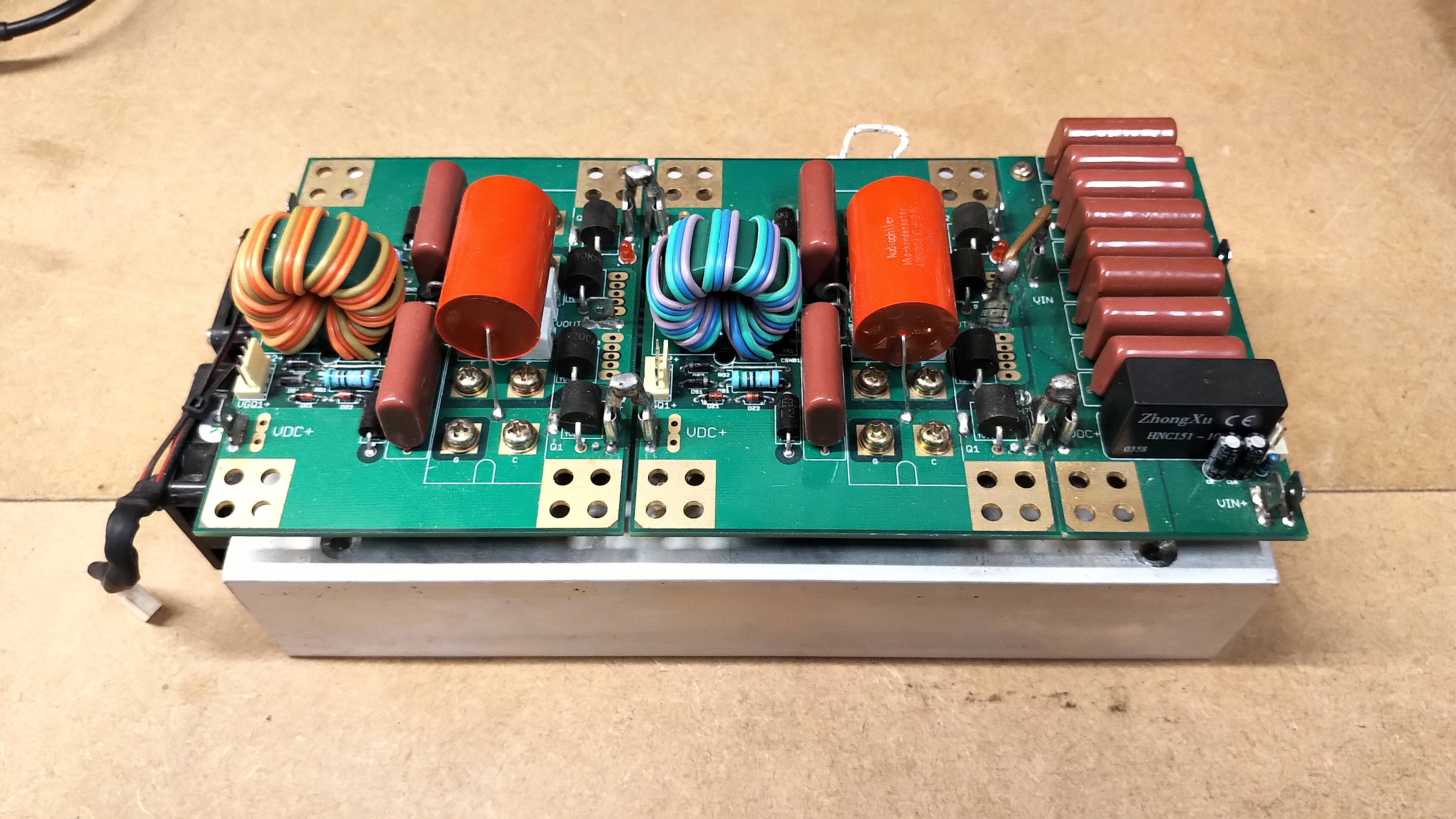
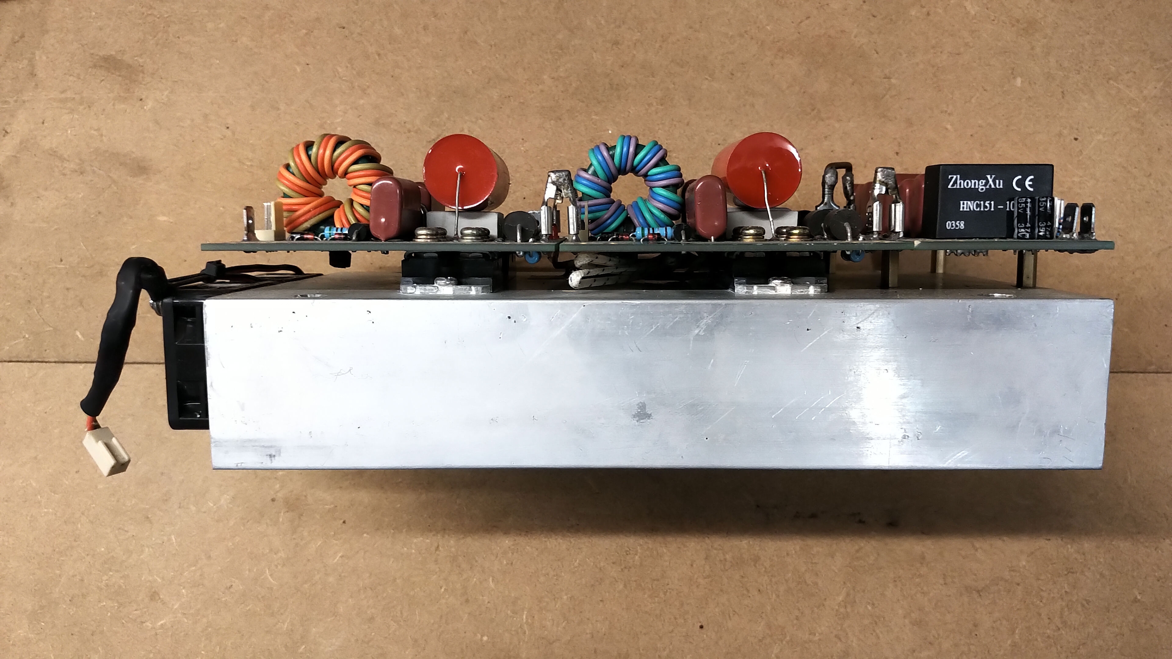
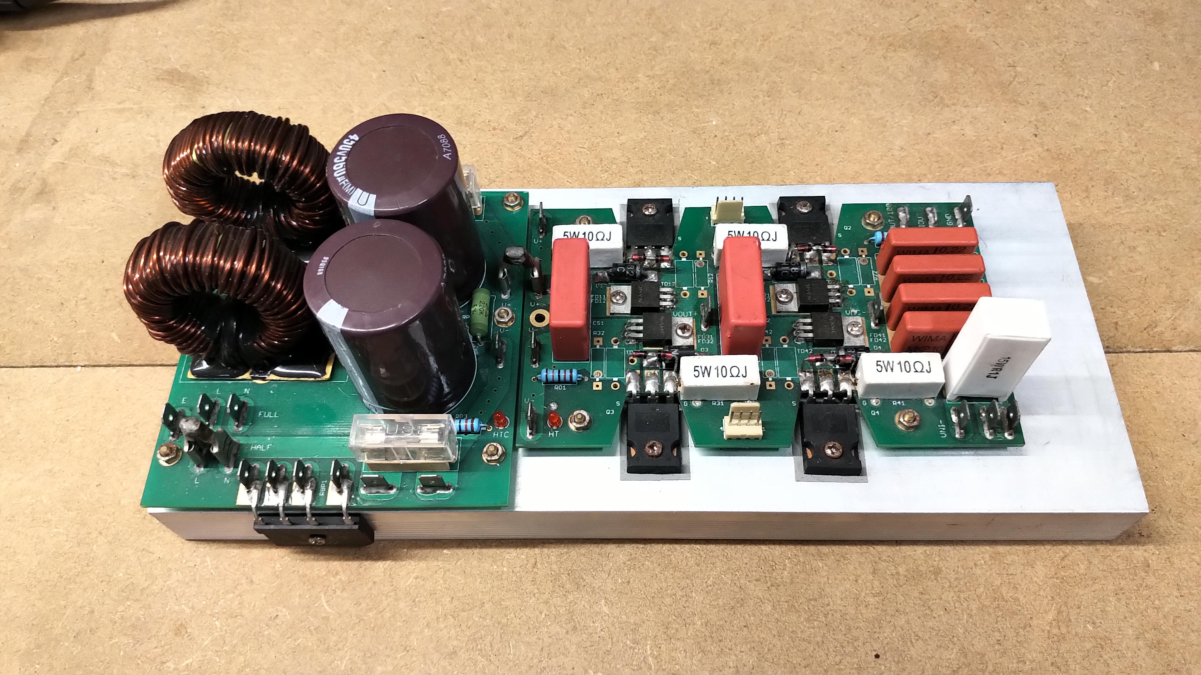
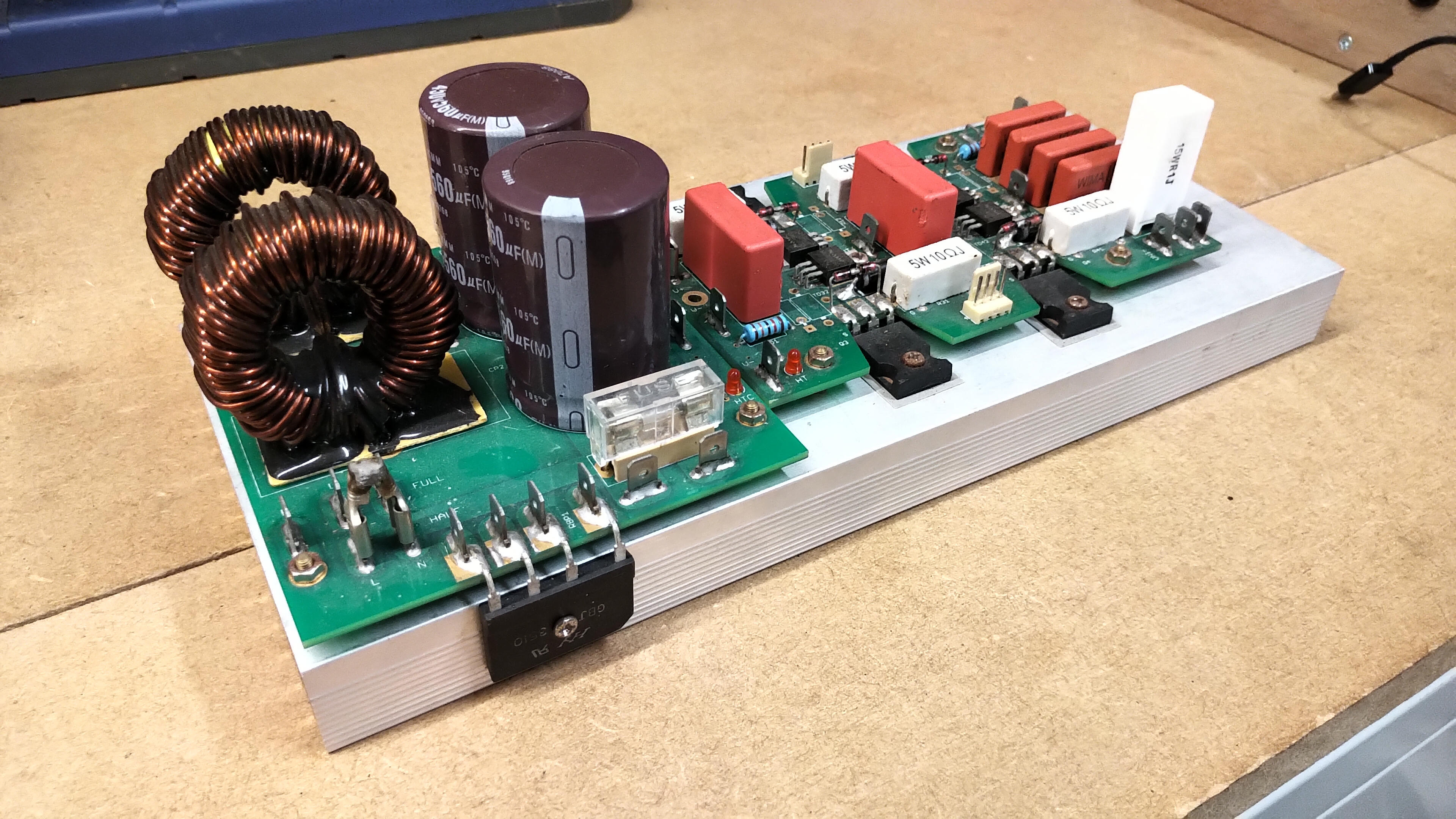
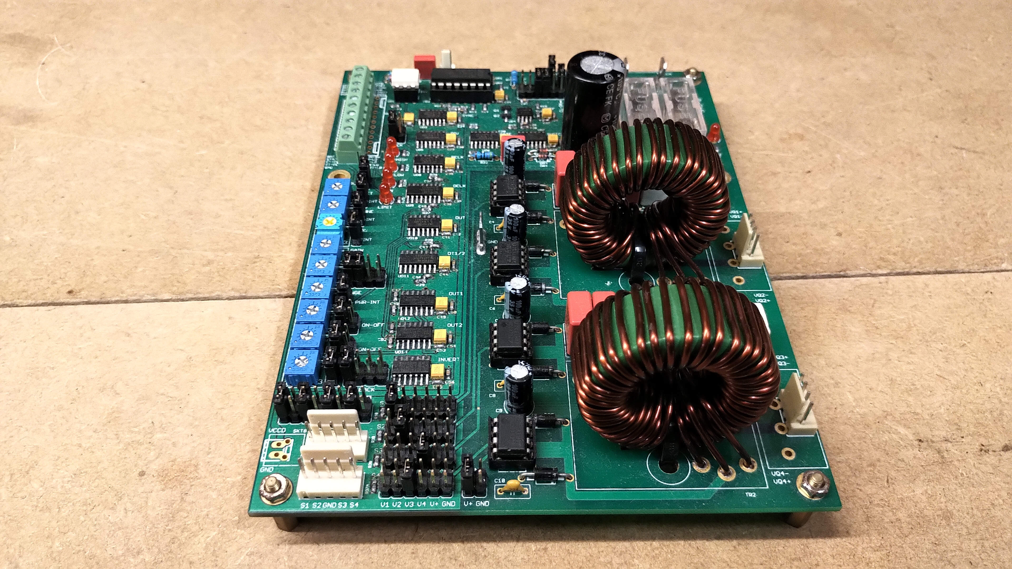
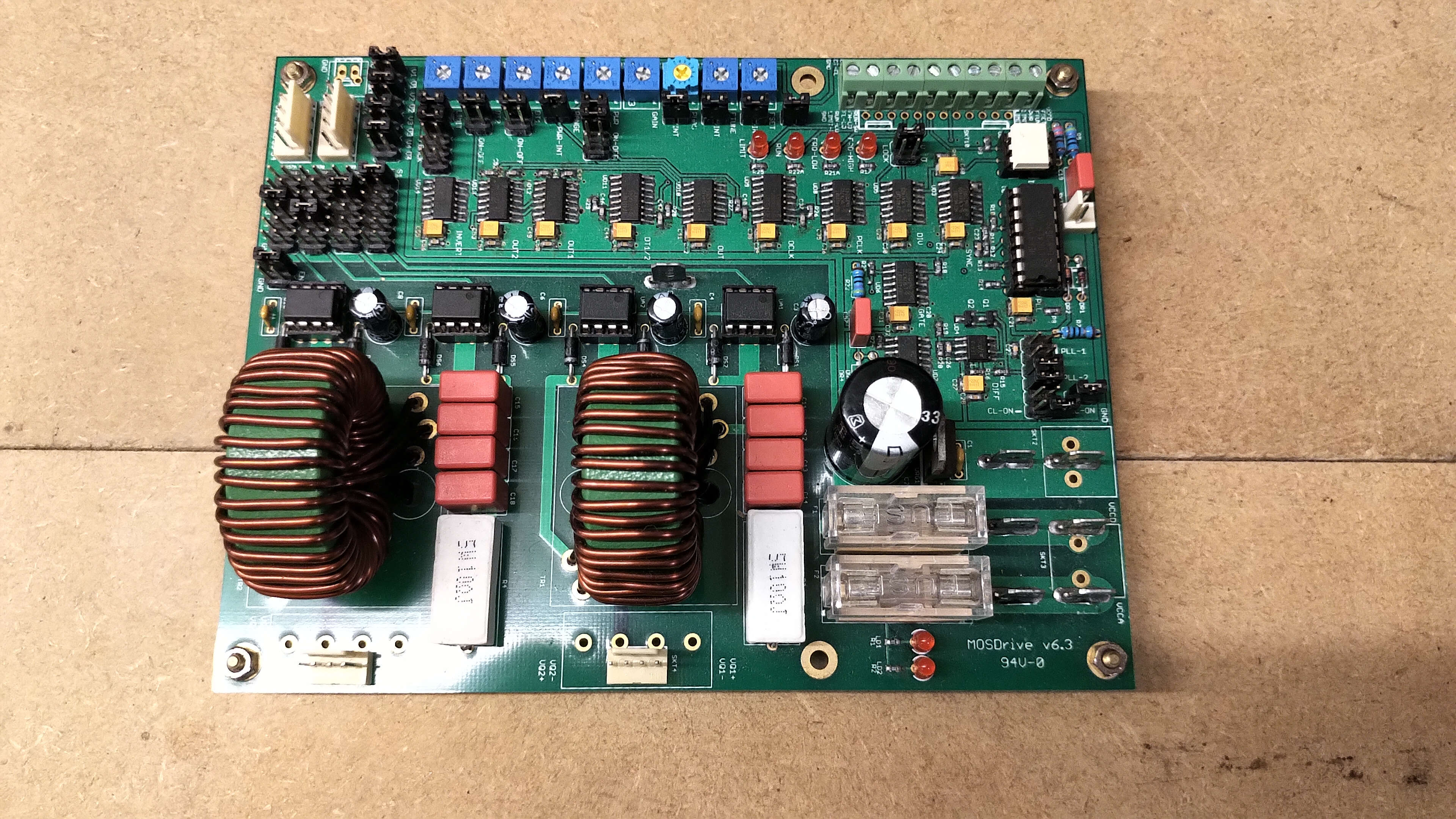
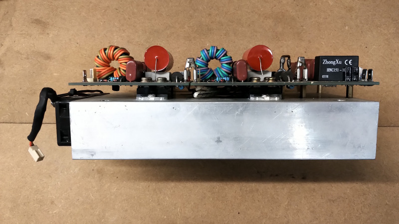
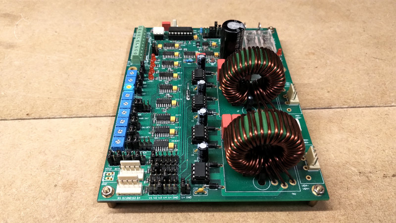
In some limited cases I have used a full-wave H-bridge semiconductor inverter to power a TC for Telluric experiments where ƒO ~ 350kc, and where the high transient primary currents create strong pulses of current into the ground system from the secondary coil. Figures 5 below show my full-wave H-bridge inverters and driver board, suitable for power experiments up to ~ 1kW. When time allows I will add a post to the generators section of the website providing the circuit diagrams, and all the details to build and operate this kind of semiconductor inverter.


Spark Discharge based with Primary Tank Circuit
This form of generator comes in many different arrangements and configurations, where the principle is to discharge energy stored in a tank capacitor in the primary circuit as quickly as possible and with minimum losses. My own implementation of a spark discharge generator, which I use extensively throughout my research is covered in previous posts Spark Gap Generator. The disruptive nature of the discharge produces a very wide-band energy discharge spectrum, and it is usually preferred with this type of generator to utilise as much of the stored tank energy as possible to resonate the secondary at its fundamental series mode resonance M2 in Fig 1.8.
To maximise the discharge currents in the primary, the impedance of the primary circuit is usually minimised just to its series resistance with no reactive components, by arranging the primary to be at series resonance at a frequency equal to, or in the case of a streamer TC just below, the fundamental series mode resonance. This is accomplished with selection of the correct series tank capacity for the primary circuit, and along with primary tuning through tapping the primary coil at the correct point. The tank capacitor is placed in series with the primary coil to form a series resonant circuit. In the case where discharge streamers are to be drawn from a top-load capacity as a power supply or otherwise, the resonant frequency of the primary is selected to be slightly less than ƒO, as a discharge will increase the loading on the secondary coil reducing its resonant frequency slightly.
Operation of a TC or TMT using a spark discharge generator can be very aggressive when the primary series resonance is matched to ƒO. In this condition, and only at moderate powers a lot of sound, light, and heat will be generated at the spark gap, and the engineering of the primary tank circuit, connections, and components, need to be robust, and well designed for sustained operation. For research purposes it is often beneficial to detune the primary some distance away from ƒO, which considerably reduces the aggressiveness of the spark gap and makes it very usable at reasonable powers for long time periods in the lab. This process of detuning and the results it generates are well covered in my posts on the Spark Gap Generator.
Matching the spark gap generator to a TC or TMT system, the fundamental series mode resonance ƒO should be used as the matching point, as this generator type is not suitable for driving the system directly at the parallel modes. The wide-band spectrum of this type of discharge generator means that it is much more tolerant of a poor match, in that you will most likely get some output from the Tesla coil even if the matching is not specifically considered. However, to get a good power output from this generator with maximum energy coupled into the secondary cavity, matching and tuning need to be carefully considered.
The series tank capacitance and tapping point for the primary coil need to arranged to a suitable series resonance either equal to ƒO, or suitably detuned to a lower frequency to smooth the spark discharge. For example, in this case of the cylindrical coil with ƒO @ M2 = 2.32Mc, and for research experiments in the transference of electric power, I often detune the primary in the range ~ 1.2 – 2.0Mc, and typically about 1.7Mc. The detuning is generally better affected to a lower frequency than ƒO, as frequencies above can start to partially energise harmonics of the secondary which leads to more complex modes of transference in the experimental cavity. Otherwise in the primary tank circuit series resistance and inductive reactance should be minimised, to maximise oscillating currents.
Overall this generator is probably the easiest to implement and use, as it is very tolerant of a poor match, which makes it an easy generator to get started with TC and TMT exploration. Properly engineered, matched and tuned, and operated this type of generator is capable of enormous power output, and more than any of the other generators covered here. It was of course Tesla’s own creation and innovation for a generator given the technology and engineering available at the time, from which he designed and constructed discharge generators capable of hundreds of kWs of power transfer[4].
Impulse Discharge Generators
This type of generator in my experience is the most interesting for observing unusual phenomena, and in my own research for working with and exploring Displacement. In its simplest form we would want to take a spark discharge generator, and arrange the tank capacitor in the primary circuit to discharge as much of its stored energy, as quickly as possible, and without creating any oscillations or ring-down in the primary circuit. In other words the discharge is uni-directional, with a discharge time constant as small as possible, with no reversal of current flow in the primary, and no back-coupling of energy from the secondary back to the primary.
In practise of course this is extremely difficult to accomplish in a simple discharge circuit, as it would involve “cutting-off” the discharge after the first maximum or pulse of the oscillation. This is something that Tesla himself claimed to accomplish with his magnetic disrupter, and if accomplished would provide an extremely high-energy, short interval, disruptive impulse. This represents a highly non-linear transient change in the system, and in my own research this type of impetus is suitable for revealing displacement phenomena and events e.g. a radiant energy emission from an under-lying coherent displacement event, within a system that is balanced and has been tuned to an operating point of maximum dynamic equilibrium and stability.
Another way to accomplish this uni-directional impulse is to use thyratron pulse generator tubes (or equivalent), which are suitable for creating very high-energy short duration pulses. Thyratron generators are more complex in design and run at much higher potentials e.g. 15kV, than high-power vacuum tube generators at ~ 4kV. This in itself makes the design and operation of a thyratron impulse generator, and its matching to a TC and TMT system, a specialised and serious undertaking. I will be covering a range of different impulse generator designs in subsequent posts, and their operation, measurement, and phenomena when used to drive TC systems into the highly non-linear region.
The cylindrical coil input impedance measurements Z11, for both a TC and TMT system, have provided a significant insight into the different modes of resonance present in this fascinating system. The data collected and analysed allows different generators to be optimally matched to different aspects of the system characteristics, including driving the transverse and longitudinal modes directly. The choice of generator combined with the coil system geometry directly effects the type of electrical phenomena that can be observed, explored, and further developed. The linear amplifier generator driven directly at the fundamental series resonant mode, and properly tuned and matched, facilitates very high-efficiency transfer of electric power, with efficiencies > 99% and measured receiver load power up to 1kW, along a single wire transmission medium no thicker than a human hair. This experiment will be video demonstrated and fully reported in a forth-coming post.
Click here to continue to the next part of cylindrical coil measurements, looking at the transmission gain S21 for a Tesla coil.
1. Tesla, N., Apparatus for Transmitting Electrical Energy, US Patent US1119732, Dec. 1, 1914.
2. Fielding, J., RF Design Basics, Radio Society of Great Britain, 2007.
3. Fielding, J., Valve Amplifiers Explained, Radio Society of Great Britain, 2017.
4. The history and design of Tesla’s wireless telecommunications facility on Eastern Long Island, Tesla Radio.