Following on from part 2 of the flat coil design it has been establised that the primary and secondary coils will be so arranged to contain equal weights of conductor, dependent on the geometry of the specific conductors being used, and so to ensure the continuity of conductor boundary conditions and hence the balance, continuity and coherence of the electric and magnetic fields of induction between the primary and the secondary coils.
It is important in the primary to maximise the current carrying capability of the coil, which will allow the generator or tank circuit to provide strong oscillations, bursts, and impulses, according to the type of experiment to be undertaken. This means that the inductive reactance of the primary should be as low as possible within the band of frequencies required, allowing a large current to flow, and whilst also allowing for a practical value of tank capacitor with sufficient adjustment to tune above and below the frequencies of interest. In this case it is intended to use a variable high voltage vacuum capacitor in the range 100pF – 1500pF, with the desired fundamental resonant frequency change at 2400kc/s occurring at a tank capacitance in the range 900pF – 1100pF which allows for good adjustment for the variable vacuum capacitor, but also for the ease of use of a fixed high voltage capacitance of 1000pF (1nF). For the tank capacitance to be 1000pF, and in the ideal theoretical case, the inductance of the primary would be 4.4uH.
Accordingly, and in consideration of the 20 turns in the secondary designed in part 1, the number of turns in the primary will be fixed at nominally 2, and with the ability to tap the primary, (for use with bare metal primary materials only e.g. copper tube or strip), slightly above or below the exact 2 turns mark should a finer resolution of tuning be required. This gives a voltage magnification in the magnifying transformer according to the secondary-primary turns ratio of 10, which is high enough to magnify the generator voltages to a more usable level in the observation and measurement of displacement events, and yet still low enough to allow high voltage generators to be used in the tank circuit without causing excessive breakout and discharge, and hence dissipation of energy to the surrounding environment, from the secondary.
Wire spacing between the turns of the primary is to be arranged to avoid any possibility of electric discharge through sparking when the primary is driven at resonance from a high voltage generator such as a vacuum tube oscillator or linear amplifier, a static or rotary spark gap generator, or other high voltage generator such as a vintage diathermy machine or electro-therapy generator. This means that the wire spacing in the primary should be safe for potentials up to 20kV applied across the primary terminals by a generator, and contacts to the primary and the primary conductor size should be able to support total input powers up to 2.5kW. With this considered the nominal distance between the start of the outer turn and the end of the second inner turn was set at 25mm, which gives a turn spacing of 12.5mm. The generally accepted dielectric strength of air at normal temperature, pressure, and humidity is 30kV/cm. When using a bare copper 3/16″ or 4.8mm tube this leaves the gap between conductors in the primary of 7.7mm which would have a nominal breakdown voltage in air of ~ 23kV, which is considered adequate for the highest voltage generators currently used in this research. The centre diameter of the primary coil was determined empirically by adjustment in relation to the secondary where the Q of the final coil was maximised, and a coupling factor between the primary and most outer turns of the secondary of ~ 0.15 was achieved.
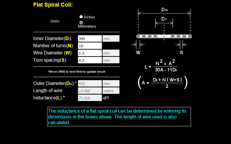
With these characteristics defined the primary wire length could be defined to best match the required characteristics. Again the spiral coil calculator was used to assist in this calculation:
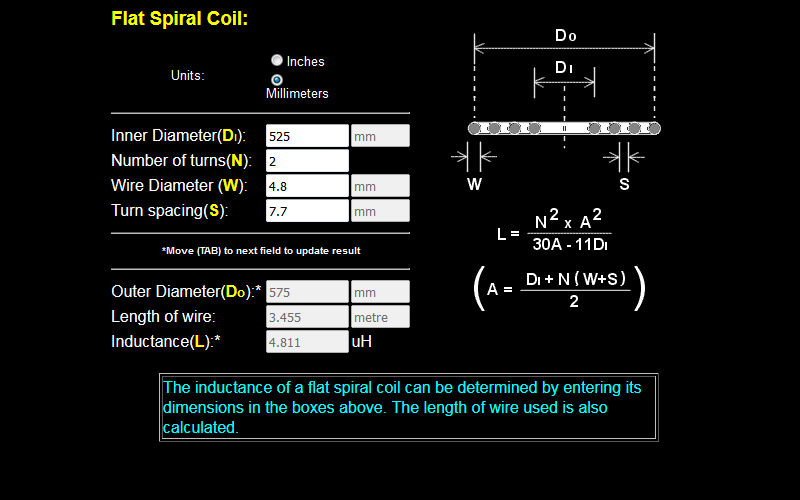

From Fig. 1. the required primary coil wire length is 3.455m, which theoretically yields a coil inductance of 4.8uH. At 2400kc/s for the desired fundamental resonant frequency phase change this yields a tank capacitance of 914pF, which is within the range required in the flat coil design.
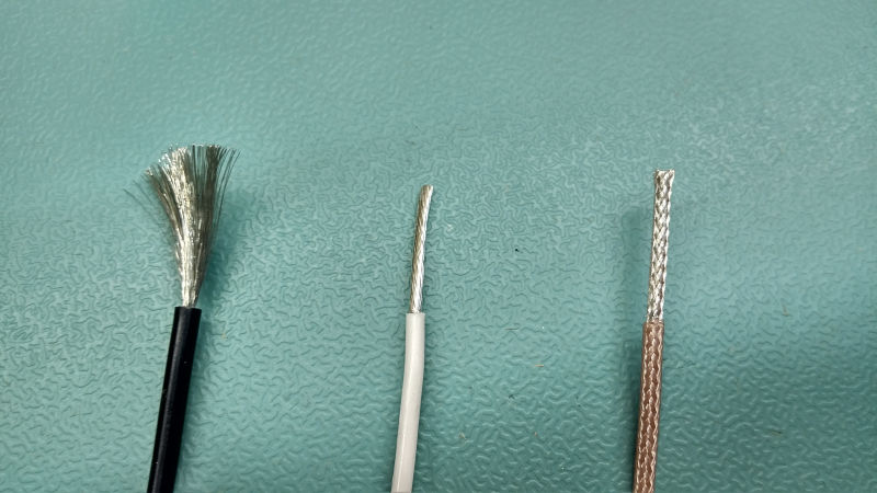
Conductors to be used / tested in the secondary coil include:
1S. PTFE / Teflon coated, silver plated, multi-stranded wire. The strong PTFE coating prevents spark or streamer breakouts from running along the length of the wire, and the silver coating bonds the jacket firmly to the inner wire conductor. Given the secondary coil properties, dimensions, and turn spacing required the wire selected as the most suitable was: Awg16, 19/0.3 (19/29), ID ~ 1.35mm, OD ~ 2.5mm, white PTFE jacket.
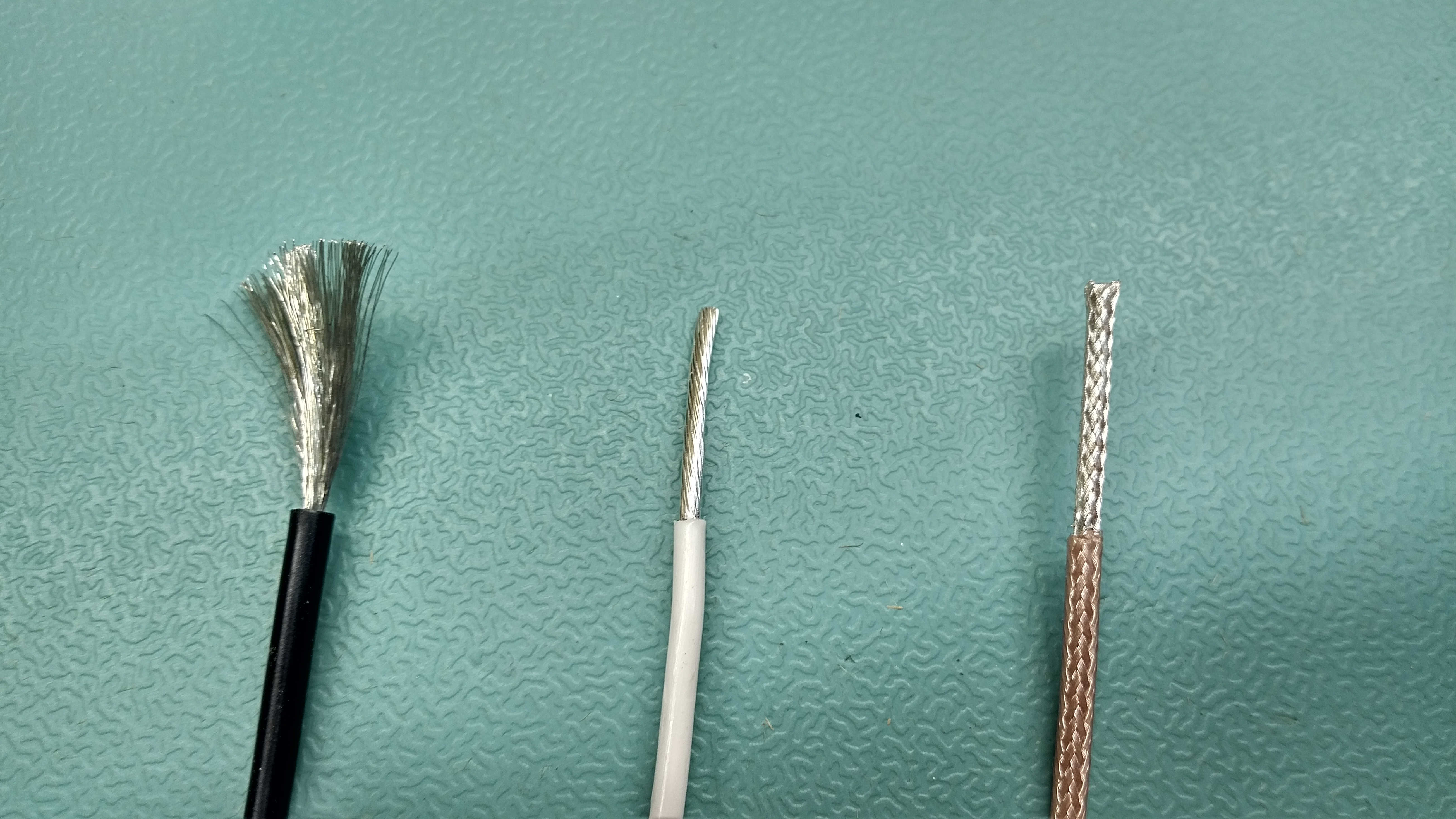
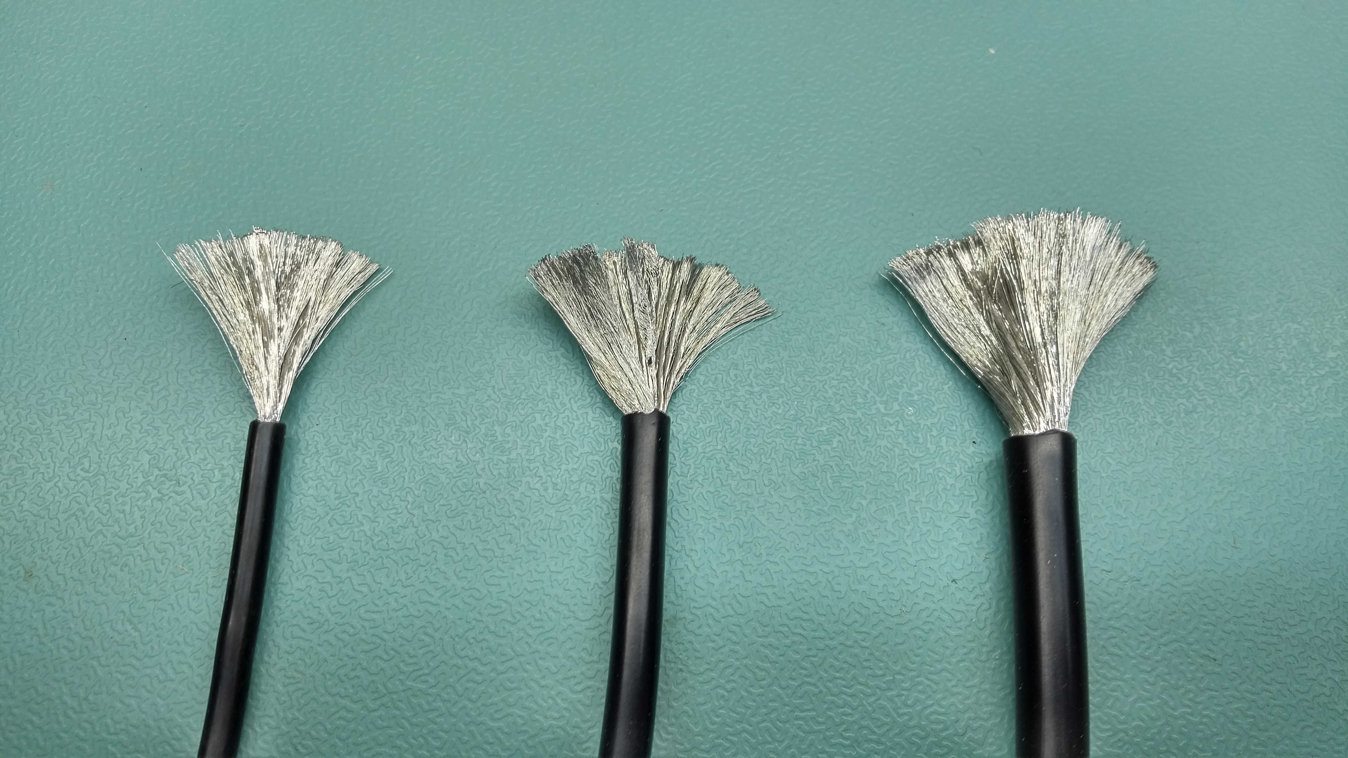
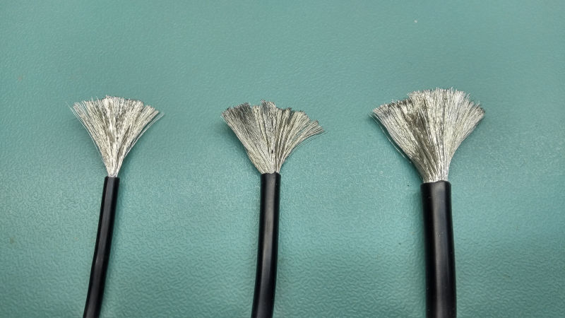
2S. Silicone coated, flexible high density micro-stranded wire. The high number of conductor strands make this wire suitable for a higher frequency, lower-loss winding, and the silicone coating makes the wire very flexible with good high voltage and temperature properties. Given the secondary coil properties, dimensions, and turn spacing required the wire selected as the most suitable was: Awg16, 252 strands, ID ~ 1.5mm, OD ~ 3.0mm, black silicone jacket.
3S. Braided shield coaxial cable. The outer shield to be used as the conductor with many strands maximising the inter-turn capacitance, and the conductor surface area, and with the inner coaxial conductor non-connected. Given the secondary coil properties, dimensions, and turn spacing required the wire selected as the most suitable was: RG316 Coaxial cable OD ~ 2.50mm, transparent Teflon jacket.
Conductors to be used / tested in the primary coil include:
1P. Silicone coated, flexible high density micro-stranded wire. The high number of conductor strands make this wire suitable for a higher frequency, lower-loss winding, and the silicone coating makes the wire very flexible with good high voltage and temperature properties.
2P. Flexible copper tubing, with good high current capability and easy primary tapping to the bare conductor surface.
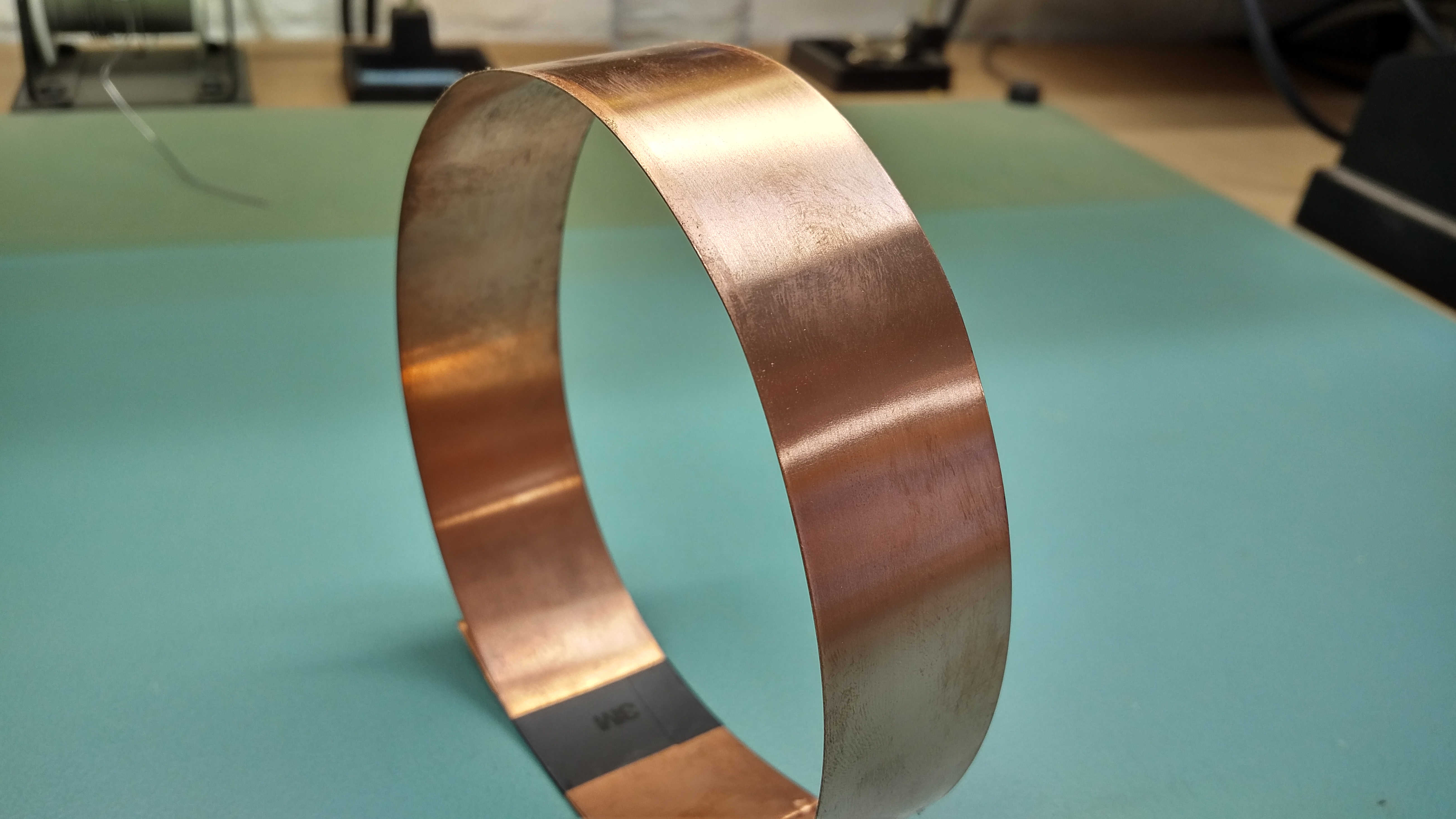
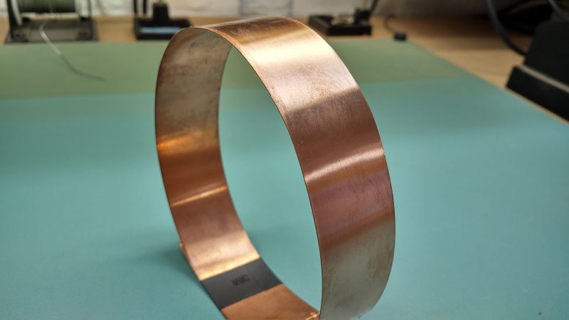
3P. Copper strip, with high surface area, high current capability, and highest Q for the high frequency experiments.

The early versions of the flat coil used wire combination 1S-1P for both the generator and load coil, providing an easy to use coil structure suitable for a wide range of preliminary investigations into the displacement and transference of electric power. This was later replaced by 1S-3P as the best measured for both the generator and load coil for experiments with displacement events. Later experiments in telluric transmission of electric power used the 1S-3P combination as the best measured generator coil, and with 3S-1P as the best measured load coil. The details of these measurements and there results will be reported in the experimental posts.
For calculations of copper weight, volume, and other useful data with respect to solid and stranded wires, and where either exact specification data, or measured data, is not available for the actual wire used, the following wire and cable data from Calmot can be used.
Click here to view or download the Calmot wire and cable data.
1. For coil 1S-1P the equal weight of copper calculation:
Secondary wire length (from part 2): 25.132 m
Specification unit weight of actual wire used: 11.120 kg/km
Secondary wire weight = 11.120 x 25.132 / 1000 = 0.279 kg
Calmot data for 8 AWG 1666 / 40: 81.1 kg/km
Actual primary wire 1P 8 AWG 1600 / 40 = 1600 / 1666 x 81.1 = 77.887 kg/km
Required primary wire length for exact equal secondary and primary weights = 0.279 x 1000 / 77.887 = 3.582 m
Calculated primary wire length from flat spiral coil calculator in Fig. 1: 3.455 m
1P Primary wire length of silicone coated micro-stranded 8 AWG 1600 / 40 = 3.58 m
2. For coil 1S-2P the equal volume of copper calculation:
Secondary wire weight (as above) = 0.279 kg
Measured unit weight of pure copper pipe OD 4.75mm (3/16″), wall thickness 0.8mm: 77.420 kg/km
Required primary wire length for exact equal secondary and primary weights = 0.279 x 1000 / 77.420 = 3.603 m
2P Primary length of 4.75mm (3/16″) pure copper pipe = 3.60 m
3. For coil 1S-3P the equal weight of copper calculation:
Secondary wire weight (as above) = 0.279 kg
Specification unit weight of pure copper strip 30mm wide and 0.3mm thick (standard strip available): 80.450 kg/km
Required primary strip length for exact equal secondary and primary weights = 0.279 x 1000 / 80.450 = 3.467 m
3P Primary length of 30mm x 0.3mm pure copper strip = 3.47 m
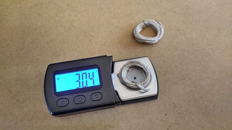
4. For coil 3S-1P the equal volume of copper calculation:
Measured unit weight of RG316 outer braid only: 6.150 kg/km
Secondary wire weight = 6.150 x 25.132 / 1000 = 0.155 kg
Actual primary wire 1P 10 AWG 1050 / 40 = 45.150 kg/km
Required primary wire length for exact equal secondary and primary weights = 0.155 x 1000 / 45.150 = 3.433 m
1P Primary wire length of silicone coated micro-stranded 10 AWG 1050 / 40 = 3.50 m (2% error to allow for 2 complete turns and connection)
All required primary lengths, (other than case 4 where the primary must be extended for 2 complete turns), are longer than the flat spiral coil calculation of 3.455m, which allows for 2 full turns of the primary and connections to be made to the primary capacitor. Connections to the primary capacitor are arranged at the point where the primary length is equal to that required to equal the weights of the secondary and primary coils.
It must also be noted that the primary capacitor introduces a weight of conductor into the primary circuit calculation which has not been accounted for above. In the experimental stage different capacitor sizes and weights will be used to determine the overall induction field mismatch caused by this circuit element and/or other elements in the generator or load. In the case of diminished displacement and transference of electric power results, the primary weight of copper will need to be adjusted through reduced AWG size (P1), reduced tube diameter (P2), and reduced strip width (P3), in order to get the best equal conductor weight match.
This concludes the three design parts for the flat coil with all the necessary parameters for construction of the final coil.
Click here to continue to the flat coil construction post.
1. A & P Electronic Media, AMInnovations by Adrian Marsh, 2019, EMediaPress
2. Dollard, E. and Energetic Forum Members, Energetic Forum, 2008 onwards.