


In this second part on the transference of electric power we take a look at the differences that arise when a spark gap generator (SGG) is used as the power source for the experiment rather than a single frequency oscillator as used in part 1. It is recommended to study part 1 before this second part, in order to gain an underlying understanding of the overall experiment, phenomena, results, and suggested interpretation of the experimental results, that are characteristic to the practical investigations in the transference of electric power.
Unlike a single frequency oscillator or linear amplifier generator, a spark gap generator produces a very broad range of frequencies which result from the abrupt and impulse-like discharge that occurs at the spark gap. Frequencies generated by such a spark gap discharge, range from the very low in the 10s of Hz, all the way up to 100s of MHz, and beyond into GHz frequencies. With such a wide frequency band the stored energy available in the tank capacitors, which are charged at each half-cycle of the HV supply, is distributed across this wide band leading to two significant factors. Firstly that considerably less energy is available from the source at the resonant frequency of the transmitter coil, and secondly, tuning of the TMT transmission system has considerably less effect on the transference of electric power between the generator source and the receiver load.
The experimental work in this part is intended to investigate and demonstrate aspects of the following:
1. Tuning measurements using a vector network analyser to measure Z11, the small signal ac input impedance for the experimental system, from the perspective of the spark gap generator.
2. Tuning indifference when powering a load either in the single wire transmission line or at the output of the receiver.
3. Reduced power available in the single wire transmission line.
4. Reduced power available in the receiver load.
5. Tesla radiant energy and matter phenomena.
6. Transference of electric power between the transmitter and receiver in the near field.
Figures 1 below show an overview of the experimental arrangement which consists of two flat coils used as transmitter and receiver and joined via the base of the secondary coils by a single wire transmission line with an inline 60W four incandescent lamp load, (4 x 15W 240V pygmy lamps). The transmitter primary is connected to the Spark Gap Generator via a matching unit which consists of two compound series tank capacitors, shunted 4 x 1B22 hydrogen-argon spark gap modulator tubes, and a 1200pF vacuum variable capacitor in parallel with the 2 turn copper strap primary.
The receiver primary is tuned by another parallel connected 1000pF vacuum variable capacitor which in turn is connected to a 50W two incandescent lamp load. The outer end terminal of the receiver primary is connected directly to RF ground via a low inductance ground strap. As in part 1 the secondary coils of the transmitter and receiver are positioned facing each other on axis 1.5m apart, and are counter-wound to each other in order to produce a balanced and reciprocal cavity arrangement.
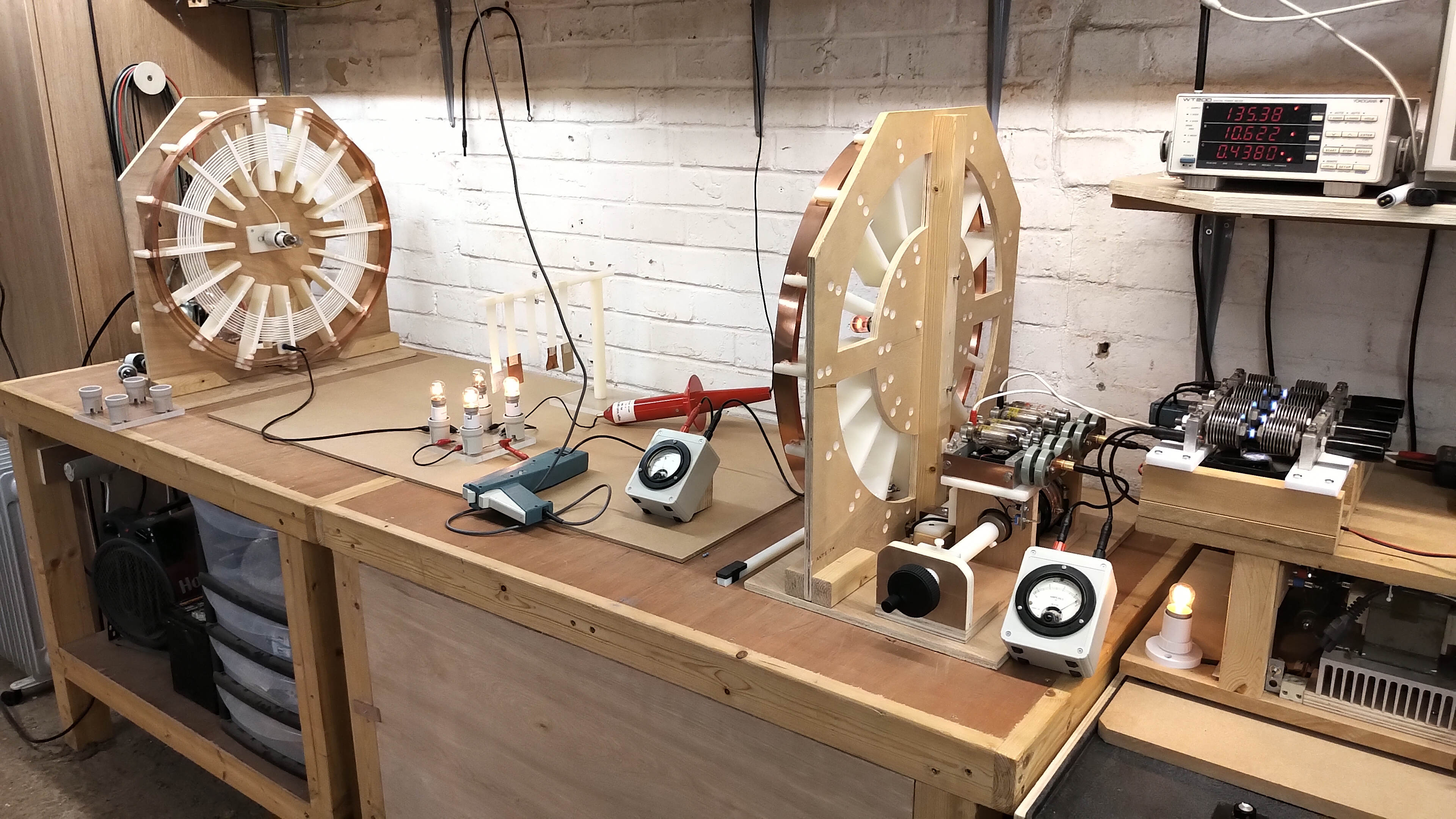
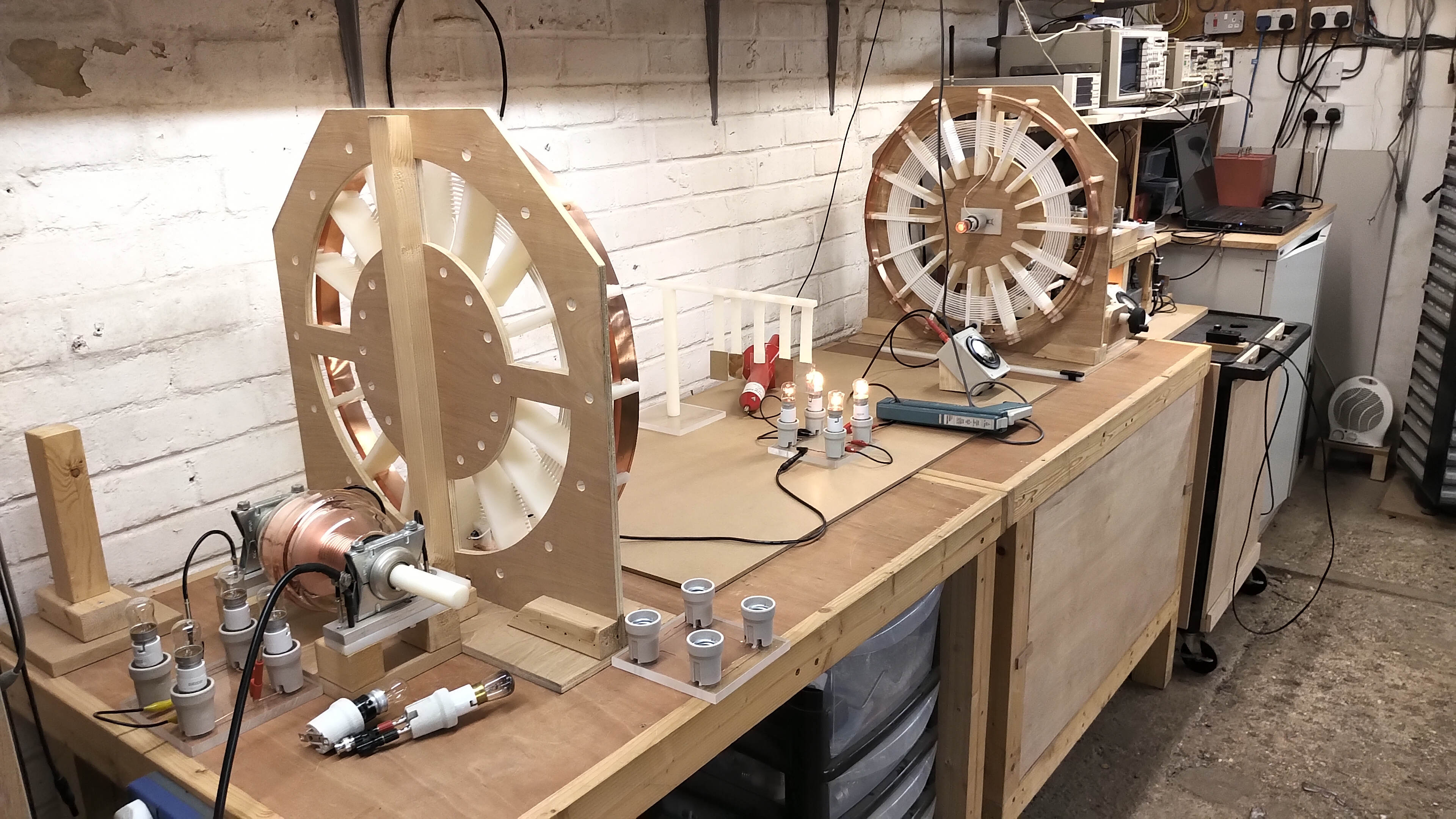
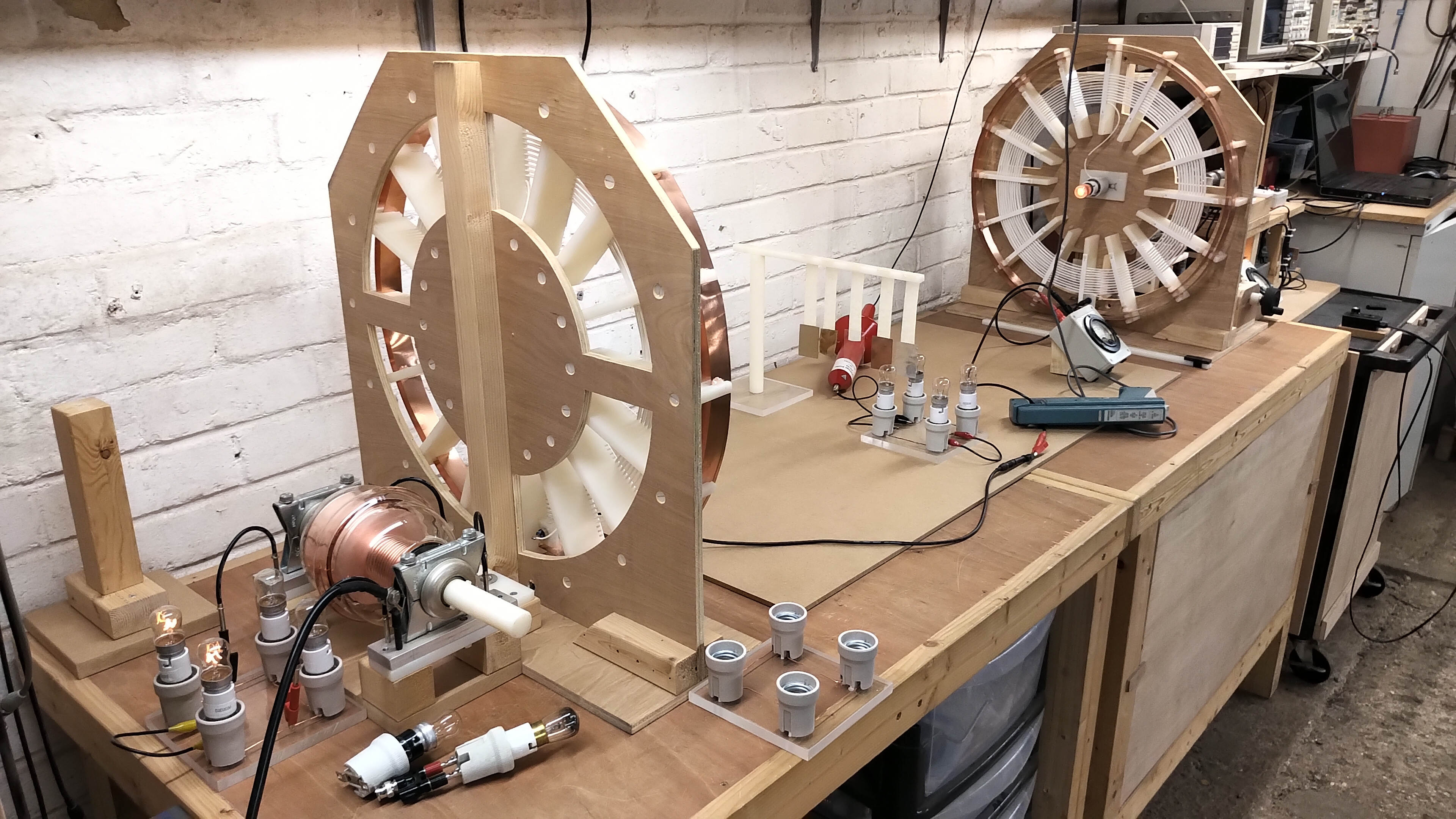
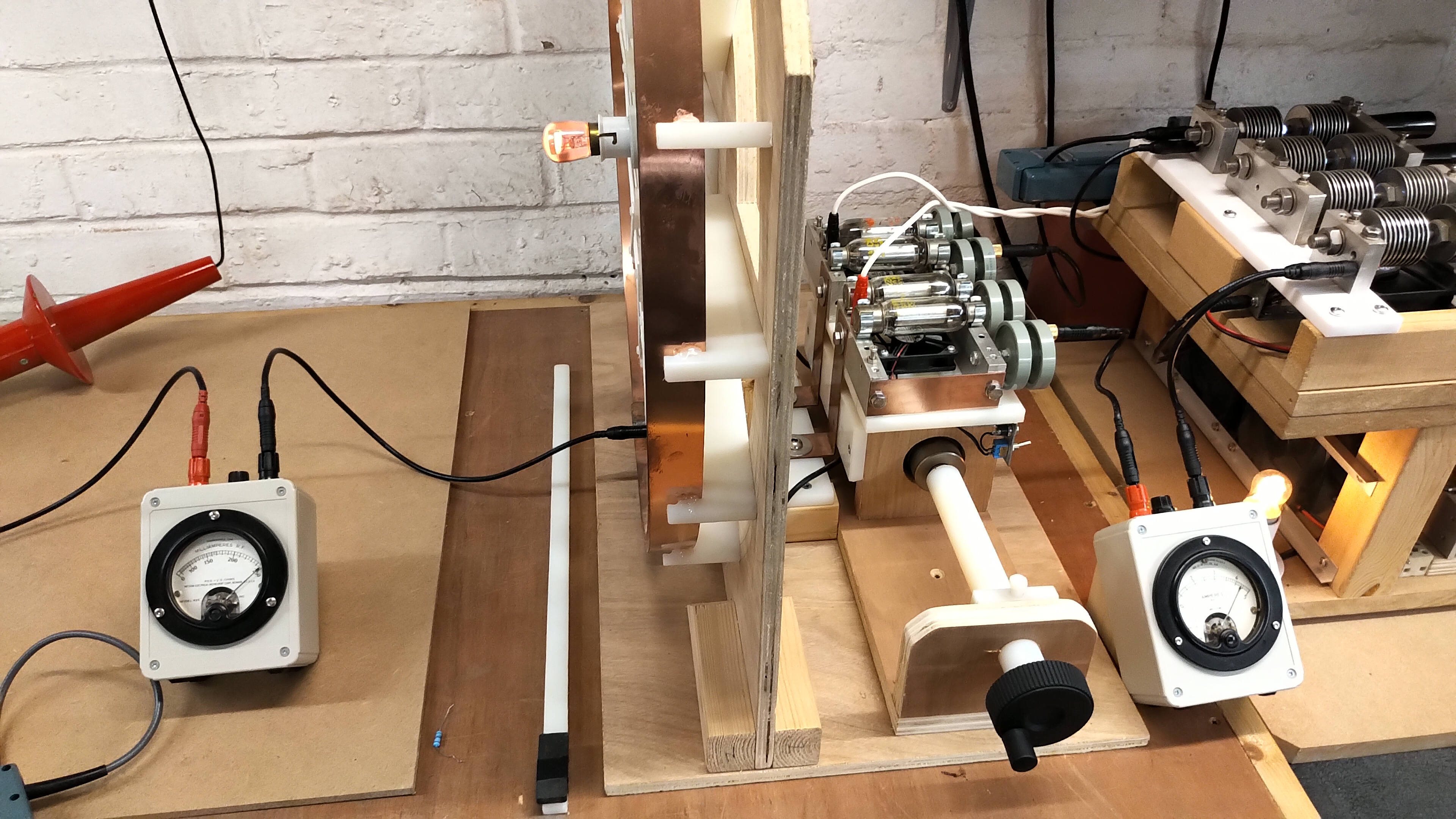
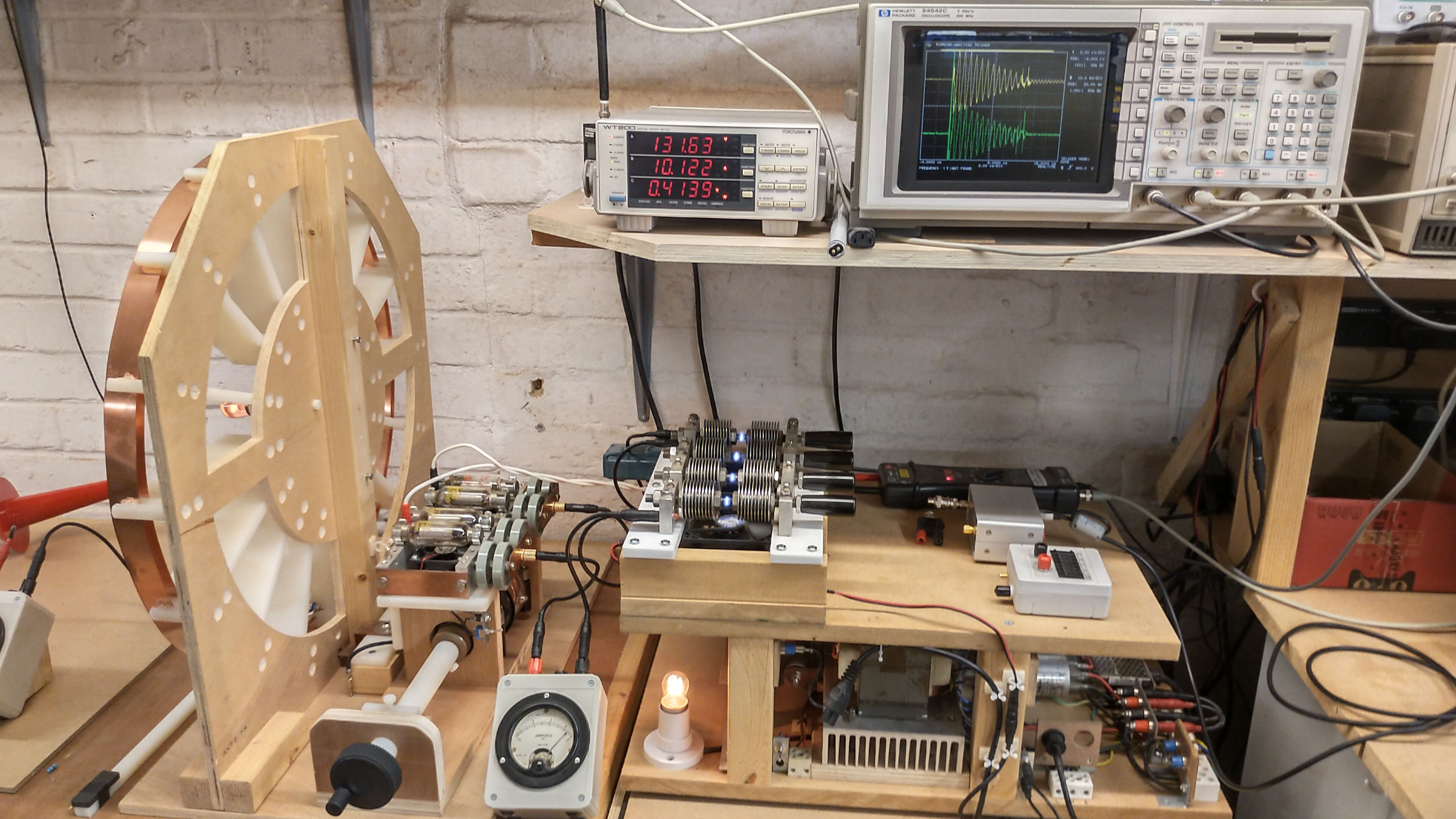
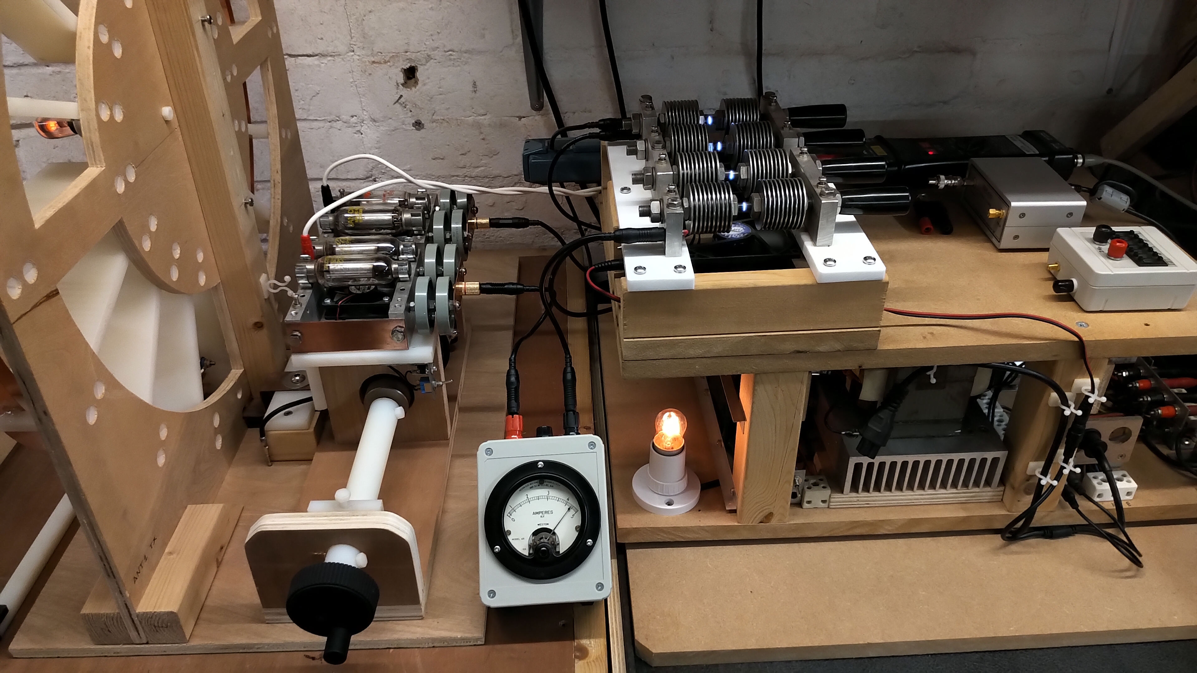


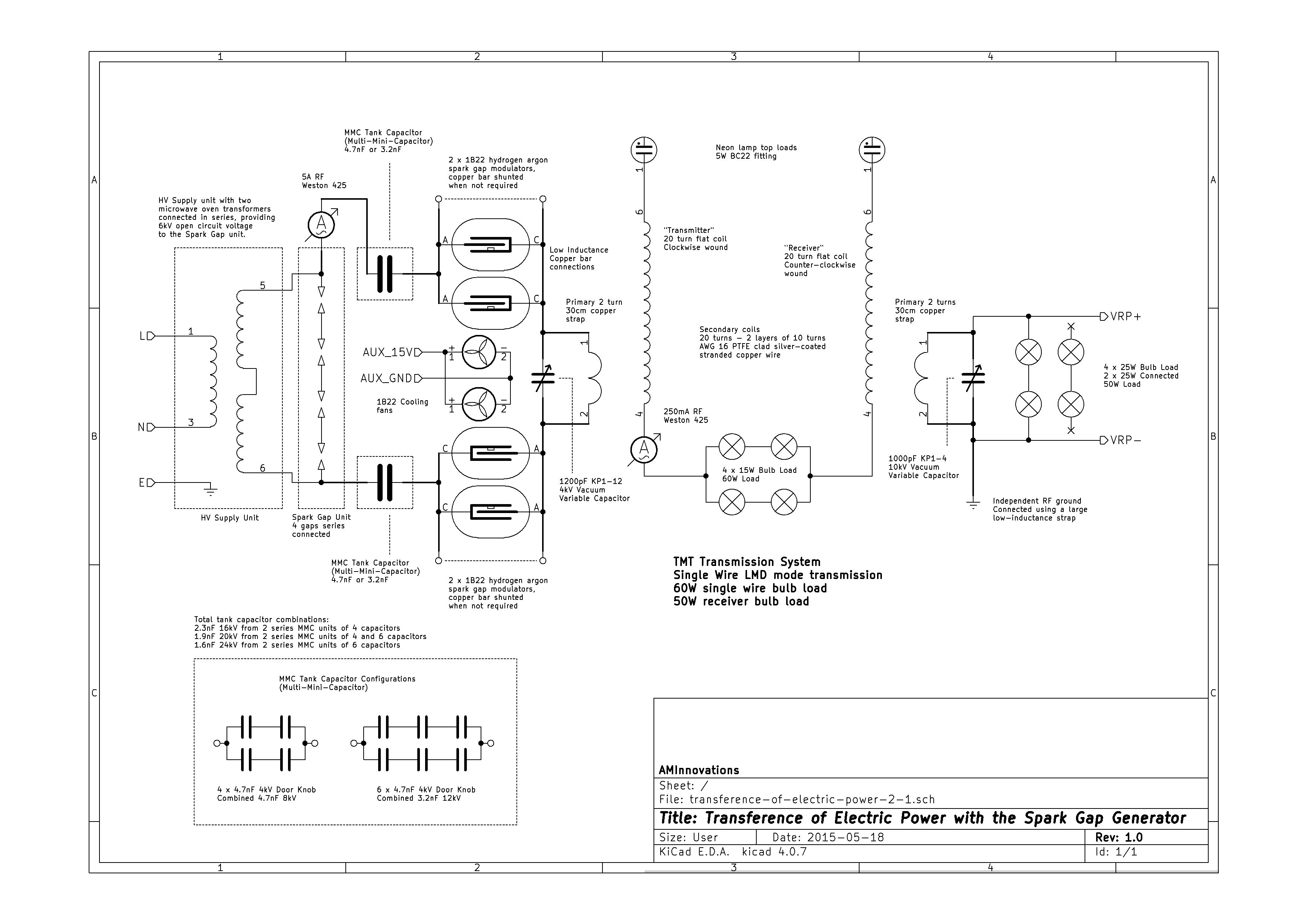
Figure 2 below show the schematic for the transference of electric power experiment powered by the SGG. The high-resolution version can be viewed by clicking here.

The principle of operation and matching requirements are somewhat different between the vacuum tube generator (VTG) and the SGG. In the VTG maximum power transfer between the generator and primary is accomplished when the impedance of the primary resonant circuit is equal to the combined vacuum tube internal impedance, when oscillating at the designed and configured operating point, (class C amplifier), for the tuned primary frequency, and run in CW (continuous wave) mode. In this case the primary circuit is not arranged to resonate at the same frequency as the secondary, where oscillating primary currents would be far too large and lead to destruction of the vacuum tubes. Rather the correct impedance match between the primary and tube oscillator facilitates maximum transfer of power from the non-resonant tube tank circuit to the tuned primary circuit, whilst keeping vacuum tube power dissipation under the maximum combined rating for the tubes.
In the SGG case it is in principle optimal to arrange the resonant frequencies of the primary tank circuit, and the secondary coil to be the same. In this case bursts of very large and maximal oscillating currents are generated in the primary tank circuit, which in turn result in strong magnetic coupling to the secondary circuit, and hence maximum power transfer between the resonant primary tank, and the secondary resonant coil. In practice matched primary tank and secondary coil resonant frequencies cause considerable operating issues when running, as the very high oscillating currents, in the high-Q low impedance primary, result in a very aggressive, unstable, and erratic spark discharge. The de-tuning of the circuit, by deliberate mis-match of the primary tank circuit resonant frequency and the secondary resonant frequency, reduces the Q considerably of the primary, reduces slightly the coupling between the primary and the secondary, whilst considerably stabilising the spark gap discharge to be suitable for experiments in the transference of electric power through a high-Q TMT transmission system.
In the case where a Tesla coil is being used for maximum streamer discharge, it is accepted as best practice to match the primary tank resonant frequency as close as possible to the secondary coil resonant frequency. Here maximum energy is coupled into the secondary and dissipated through the top-load accumulator. In this case the primary frequency is usually de-tuned slightly below the secondary frequency to maximise power transfer during streamer discharge, which leads to very white-hot powerful discharges. For example for a coil arranged to resonate with suitable top-load at 1.7Mc/s the primary resonant tank circuit would be tuned to resonate between ~ 1.5-1.6Mc/s, (~10% lower to compensate for secondary frequency drop on discharge). This case requires a very powerful and robust spark gap that will operate very aggressively, unstably, and producing large amounts of heat, light and noise.
In the case for a TMT transmission system using two or more Tesla coils matched and tuned together in a high-Q narrow bandwidth arrangement, and connected with a single wire and operated in a balanced LMD transmission mode, the primary resonant tank frequency is optimally arranged to be lower in frequency than the secondary resonant coil frequency. In this case there is only a small measured difference in total power being transferred from the generator to the final receiver load as a result of the deliberate primary resonant tank and secondary coil resonant frequency mis-match. For example for a coil arranged to free resonate into a single wire transmission line at 1.7Mc/s the primary resonant tank circuit would be tuned to resonate between ~ 1.0-1.3Mc/s.
The 1B22 hydrogen-argon spark gap tubes were shunted out of the circuit for experiments in the transference of electric power to the receiver load, as their higher internal resistance reduces the primary currents, causing a reduction in the total transmitted power. The shunts are made from copper sheet which remove the tubes from the circuit without increasing the inductance of the primary tank circuit. In experiments relating to Tesla’s radiant energy and matter it is possible to obtain improved results, (amplified phenomena), when the 1B22 tubes are included in the circuit. It is conjectured that the slight dioding action[1,2] as a result of the ionizing radioactive (Radium Ra-226) trigger element, and the improved pulse response of the primary tank circuit, improves the uni-directional energy supply from the tank circuit to the TMT system. This improved uni-directional energy supply increases the intensity of the LMD mode wavefront in the single wire cavity, amplifying radiant energy and matter phenomena.
A correctly triggered and functioning 1B22 will emit a dark purple spark discharge within the aluminium can of the cathode terminal, which is quickly quenched by the rarefied hydrogen-argon gas mix. A defective 1B22 with a leak to air will still work as a spark gap but will generate a brighter green-yellow discharge as aluminium is combusted from the cathode surface. The discharge sustains for longer causing considerable burning of the electrodes, and rapid over-heating causes distortion of the glass tube, with finally destruction of the electrodes.
The following video introduces the experimental setup, instrumentation, and readings, and looks in detail at Z11 the small signal impedance characteristics of the experiment from the perspective of the spark gap generator. It concludes with a range of experiments in the transference of electric power using a spark gap generator, combined with a preliminary introduction to Tesla’s radiant energy and matter experiments.
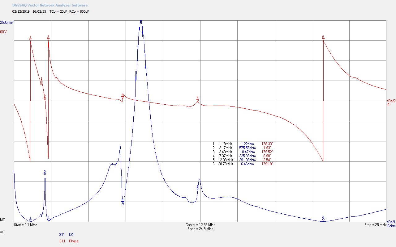
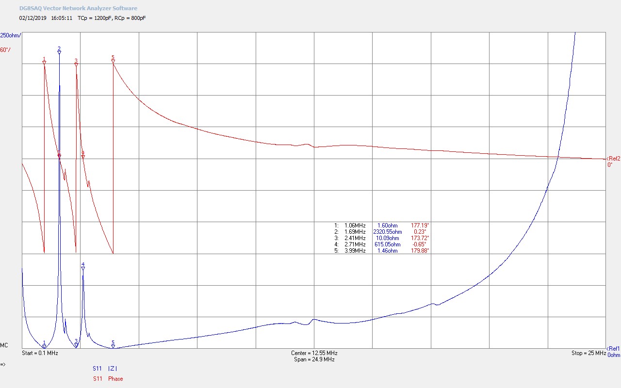
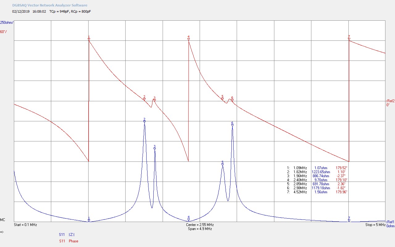
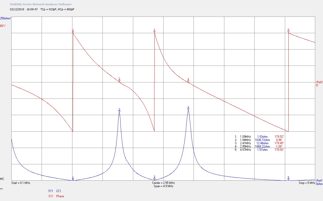
Figures 3 below show the detailed Z11 impedance measurements that were presented in the video, and will be referred to in the consideration of the experimental results.


Figures 4 below show the oscillating voltages and currents in the primary transmitter tank circuit, and also those measured at the single wire load. In both the green and red traces the current amplifier is calibrated at 50A/div, showing the large oscillating currents that occur in the primary, and those transferred to the burst in the secondary.


The principle of operation of the transmitter coil primary tank circuit is explained in detail in the post Spark Gap Generator – Part 2. In fig. 4.2 the current (red) in the single wire medium has become far more impulse-like in nature, rather than the oscillating sinusoidal established in the primary coil ring-down as the tank capacitors discharge in the series resonant tank circuit. It is conjectured that these impulse-like currents may be indicative of the burst wavefront constituting the LMD mode, within the cavity formed between the transmitter and receiver coil top-loads. It may also indicate more clearly why it is possible to observe radiant energy and matter phenomena more easily in a SGG driven TMT system, compared to a VTG or linear amplifier driven TMT system. That is, the nature of the burst currents generated in the primary resonant tank circuit by the SGG generator lend themselves more readily, when induced into the secondary cavity, to the LMD mode in the form of impulse-like, uni-directional bursts. These more uni-directional bursts in turn lead to an intensified wavefront in the cavity and the clearer observation of Tesla’s radiant energy and matter phenomena. This experimental area will be explored in much more detail in subsequent posts, but for now serves as an empirical introduction to these fascinating phenomena.
Fig. 4.1. shows the oscillating voltage and currents generated by the SGG in the primary resonant tank circuit. The oscillating currents (green) are a product of the stored energy in the tank capacitors repeatedly transferred backwards and forwards between the tank capacitors and the inductance of the primary coil. As the stored energy is consumed by transfer to the secondary circuit, and by dissipation as heat, light, and noise in the spark gap, and the series resistances of the primary tank circuit, the envelope of the primary current decays until all stored energy in the current cycle is expended. The oscillating nature of the current when transferred from the primary to the secondary tends to cause “dragging” or “smearing” of the LMD wavefront in the secondary cavity reducing the potency and impact of the pressurised wavefront.
In the most ideal case the wavefront would constitute a single pulse of very large amplitude and with very short pulse width, resembling as closely as possible a true impulse function. This pulse wavefront would traverse the cavity in a uni-directional manner with no reflections or dispersion leading to a singular and positive acting pressure wave with both the di-electric and magnetic fields of induction coherently in phase. In this ideal case the transfer of electric power could be 100% between transmitter and receiver, or if radiant energy phenomena are so arranged by a suitable load or emitter in the single wire transmission medium of the cavity, 100% wireless transfer of electric power could be arranged between many points. The intense radiant energy burst from the strong wavefront may also generate a wide range of unusual and hitherto unexplored electrical and matter phenomena, which may in turn also assist in the experimental exploration of the displacement of electric power, the hidden underlying coherent guiding principle of the undifferentiated electric and magnetic fields of induction.
This most ideal case requires that in the primary tank circuit all the energy stored in the tank capacitor per cycle is transferred to the secondary within the first half-cycle of the ring-down. This would create a single pulse from each cycle where all energy available in the tank circuit is transferred to the secondary, in effect driving the primary with a pulse generator. In order to do this it would be necessary to quench the spark gap after the first half-cycle of the discharge, and also ensure that the impedance of the primary circuit was sufficiently low that all the stored energy in the tank could be discharged in this first half-cycle. Both of these requirements present very challenging practical implementations, and will be explored in more detail in subsequent posts.
Tank circuit capacitance optimisation
In the current primary circuit the tank capacitance was adjusted in three different configurations in order to find the optimum operating point for the experiments in the transference of electric power powered by the SGG. The circuit diagram in figure 2 shows the arrangement of the tank capacitor in these three configurations:
1. 2.3nF 16kV from two series MMC units of four capacitors each. This is the tank capacity used in the video experiment and is very stable with only a very small reduction in the amount of power transferred to the receiver load. From figs. 3.3 and 3.4 the resonant frequency of the series primary tank at M1 is 1.09Mc/s. Good stable operation could be established up to ~800W.
2. 1.9nF 20kV from two series MMC units of four and six capacitors respectively. This tank capacity increased slightly the amount of power transferred to the receiver load over configuration 1, but the unbalanced capacity either side of the primary coil, (4 cap. unit one side, 6 cap. unit the other side), was found to lead to more instability in the spark discharge including “popping” and material ejection at the electrodes at powers only up to 500W. The resonant frequency of the tank circuit in this configuration is ~ 1.2Mc/s
3. 1.6nF 24kV from two series MMC units of six capacitors each. This was found to be the lowest practical tank capacity when running at powers up to 1kW. Lower than this the spark gap became too aggressive and erratic for good accurate measurements and stability in the transference of electric power. The resonant frequency of the tank circuit in this configuration is ~ 1.3Mc/s
Overall, configuration 1 was selected for most experiments in the transference of electric power, providing the best balance between longer-term stable and reliable operation of the spark gap, and with acceptable energy transfer to the transmitter secondary coil.
The other feature of the tank circuit was to minimise the inductance of the connections and components. The optimum condition is for all the current in the tank circuit to contribute to generating a magnetic field only within the primary coil itself, which maximizes the magnetic field coupling to the secondary coil. In practise magnetic fields are also created around the inductance of the tank circuit connections and components, storing some of the available tank circuit energy, and reducing the magnetic field generated within the primary coil. The inductance of the tank circuit components is kept minimum by keeping connection wires short and made from large many stranded conductors, by using copper busbars, and solid aluminium or copper mounting blocks for larger components. In the circuit diagram of fig. 2 the low inductance parts of the tank circuit extend from the spark gap to the primary coil and are indicated by thicker connecting wires.
Tuning indifference when powering a load
One of the most notable differences between the experiments in part 1 and 2, is that power dissipated in the both the single wire load and the receiver load varies only slightly with large changes to the transmitter and receiver primary tuning capacitor. The transmitter tuning capacitor was varied over the range 20-1200pF which in figs. 3.1 and 3.2 shows very large changes to the frequency spectrum of the TMT system. However when powered from a properly adjusted spark gap generator the bulbs in the single wire transmission medium remain well-lit over much of the tuning range. This is in stark contrast to part 1 where power dissipated or transferred in the various loads were very dependent on the tuning condition of the transmitter and receiver, and to the matching conditions of the VTG to the primary of the transmitter.
In fig. 4.2 we see that currents in the single wire transmission medium are much more impulse-like and consist of many narrow pulse excitations and rapid bursts. The spectral content of this time-domain signal will be very wide with energy distributed over a very broad-bandwidth, and consistent with the properties of the spark gap stimulus in the primary circuit. With such a wide bandwidth of frequencies present at the single wire load we would expect the bulbs to be illuminated irrespective of the tuning in the transmitter primary. Many frequencies are being transferred from the primary to the secondary circuit which is characteristic and typical of the properties of this experiment when driven from a spark gap based generator.
Given the above as a broad comparison with the experiment in part 1, tuning around the upper and lower resonant frequencies of the flat coil transmitter causes a slight increase in brightness for the single wire load, showing that more energy is selectively coupled at these frequencies from the generator as would also be expected from part 1, and from the frequency characteristics measured in figs. 3.1-3.4.
Reduced power in the single wire load and receiver load
The spread of energy over a very wide bandwidth results in less energy being dissipated in both the single wire load and also in the receiver load, as compared the single frequency oscillator experiment in part 1.
1. In the case of the single wire load, the bulbs can still be lit to almost full brightness since all the power from all transferred frequencies is being dissipated in this load. The bulb brightness showing the average power dissipation over many bursts coming from the spark gap generator. At an input power of 300W to the HV supply it was possible to illuminate the single wire load to around two-thirds of its maximum rating, so ~45W. At 500W the load could be illuminated fully to ~60W.
2. In the case of the receiver load, much less power could be coupled into this load even when tuned correctly as a complete TMT system, as shown in figs. 3.3 and 3.4. The single wire load had to be first removed to prevent power dissipation at this load, and then the receiver load could be illuminated to maximum ~0.5 of its total power e.g. about 25W. From the wide-band of frequencies available in the single wire transmission medium only a very narrow range at the resonant frequency of the receiver flat coil are transferred from the single wire to the receiver load. It should however be noted that the receiver bulb loads where illuminated dimly over the entire tuning range of the transmitter primary and the receiver primary. This again shows that a little of that wide bandwidth of energy is coupled to the receiver irrespective of the tuning, again tuning indifference based on the spectral content of the source energy.
In this case the spark gap generator is far from optimal for the transference of electric power, where for the same input power as in part 1, less energy is transferred to the single wire load, and very much less energy can be transferred to the receiver load. This proves to be the case even when the TMT system is optimally tuned as shown in figs. 3.3 and 3.4, and by further comparison with the optimal tuning results in part 1 of this experiment.
Tesla radiant energy and matter phenomena
These phenomena form some of the most interesting and unusual aspects of this TMT experiment using a spark gap generator. Whilst these effects can also be observed in the same experiment using a single frequency oscillator, linear amplifier, or other oscillating source they are much reduced in intensity when compared with a spark gap generator, burst oscillator, pulse generator, or properly designed and operated impulse or displacement generator. The exploration of these phenomena in this experiment is only as an introduction to these effects, and properly requires a much more detailed experimentation and consideration, which will be presented in a subsequent post along with very much magnified phenomena results.
The preliminary phenomena observed in this experiment include:
1. Attracting metals to the surface of an incandescent bulb in the single wire cavity, where the bulb acts as an emitter of radiant energy.
2. Amplification or intensification of a radiant energy event by interaction with a living organism, (human hand).
3. Charging a capacitor with radiant energy by bringing it close to the emitting bulb.
4. Radiant matter pressure waves emanating from the emitting bulb and impacting on a living organism, (human hand).
It should be noted here that improving the uni-directional pulse nature of the generator system by, for example, including components such as 1B22 spark gap modulator tubes in the tank circuit, early magnetic quenching of the spark discharge, or other impulse/pulse/burst generation methods, considerably magnifies the observed phenomena. It is also important to note that these types of phenomena are best observed when a cavity has been established using a resonant transformer, such as a Tesla coil, and where a longitudinal pressure wavefront is established within the cavity, preferably in an LMD type mode, or ideally with direct displacement.
Summary of the results and conclusions so far:
The transference of electric power experiment using the tuned TMT flat coil system has produced considerably different results when powered using a spark gap generator, as compared with the single frequency feedback oscillator in part 1. The key differences and results include the following:
1. Tuning indifference occurs due to the wide spectral bandwidth of the energy transferred from the generator to the final receiver load, and impacting on all parts of the TMT transmission system between these points.
2. Considerably reduced levels of transferred electric power both to the single wire transmission medium load, and the receiver load, for the same nominal input power to the HV supply of 300W. Again this is attributed to the diffuse spectral energy content when a wide bandwidth generator is connected to a narrow bandwidth high-Q TMT transmission system.
3. Tank circuit tuning configurations have shown that a de-tuned primary and secondary resonant frequency in the transmitter primary leads to the best balance between transferred electric power, and stable, consistent, and long-term reliable operating conditions.
4. Radiant energy and matter phenomena have been observed in the experiment, and indicate components and optimizations, including different generator configurations, that will intensify and maximise these unusual observations.
5. Generator configurations and types that improve the impulse/pulse/burst nature of the transferred energy may intensify radiant energy phenomena by generating a more uni-directional pressure wavefront in longitudinal system, which may also provide additional insight into the preliminary investigations into the displacement of electric power.
The results for the transference of electric power in the near-field using a spark gap generator indicate that this form of generator is not well suited for energy transmission in the narrow bandwidth high-Q TMT system. A very large and robust spark gap generator would be required to transfer adequate power from generator to load, with considerable losses at the spark gap, huge electromagnetic interference to the surrounding medium, and invasive and unstable operating conditions. However this form of generator does appear to lend itself to phenomena that arise from the longitudinal pressure wavefront generated in the cavity of a resonant transformer, such as a Tesla coil. As such it is conjectured that this form of generator may be useful in the exploration of displacement, the hidden underlying coherent guiding principle of the undifferentiated electric and magnetic fields of induction.
Click here to continue to the next part, looking at High-Efficiency Transference of Electric Power.
1. Dollard, E. & Lindemann, P. & Brown, T., Tesla’s Longitudinal Electricity, Borderland Sciences Video, 1987.
2. Dollard, E. and Energetic Forum Members, Energetic Forum, 2008 onwards.