


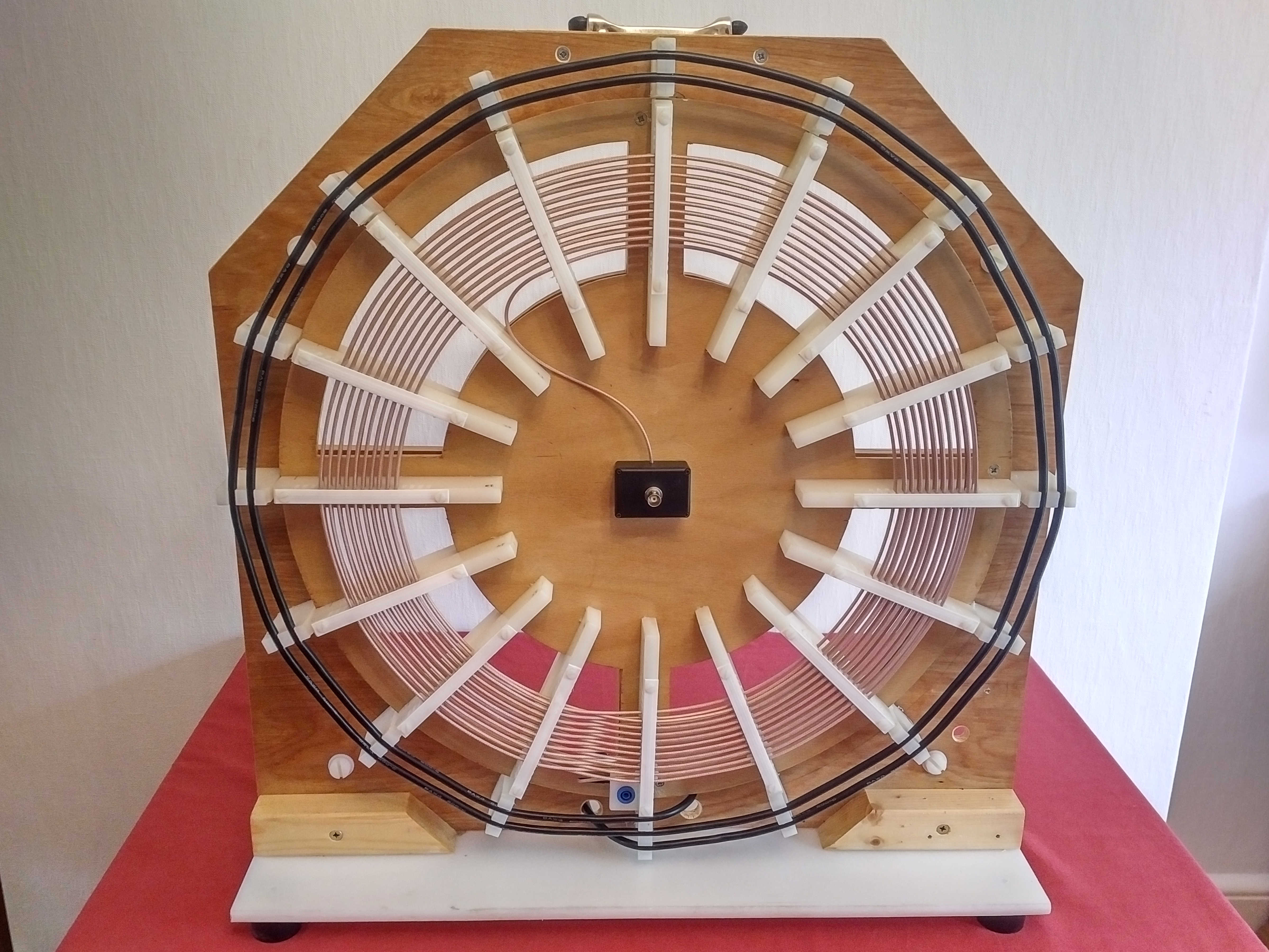
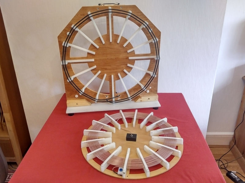
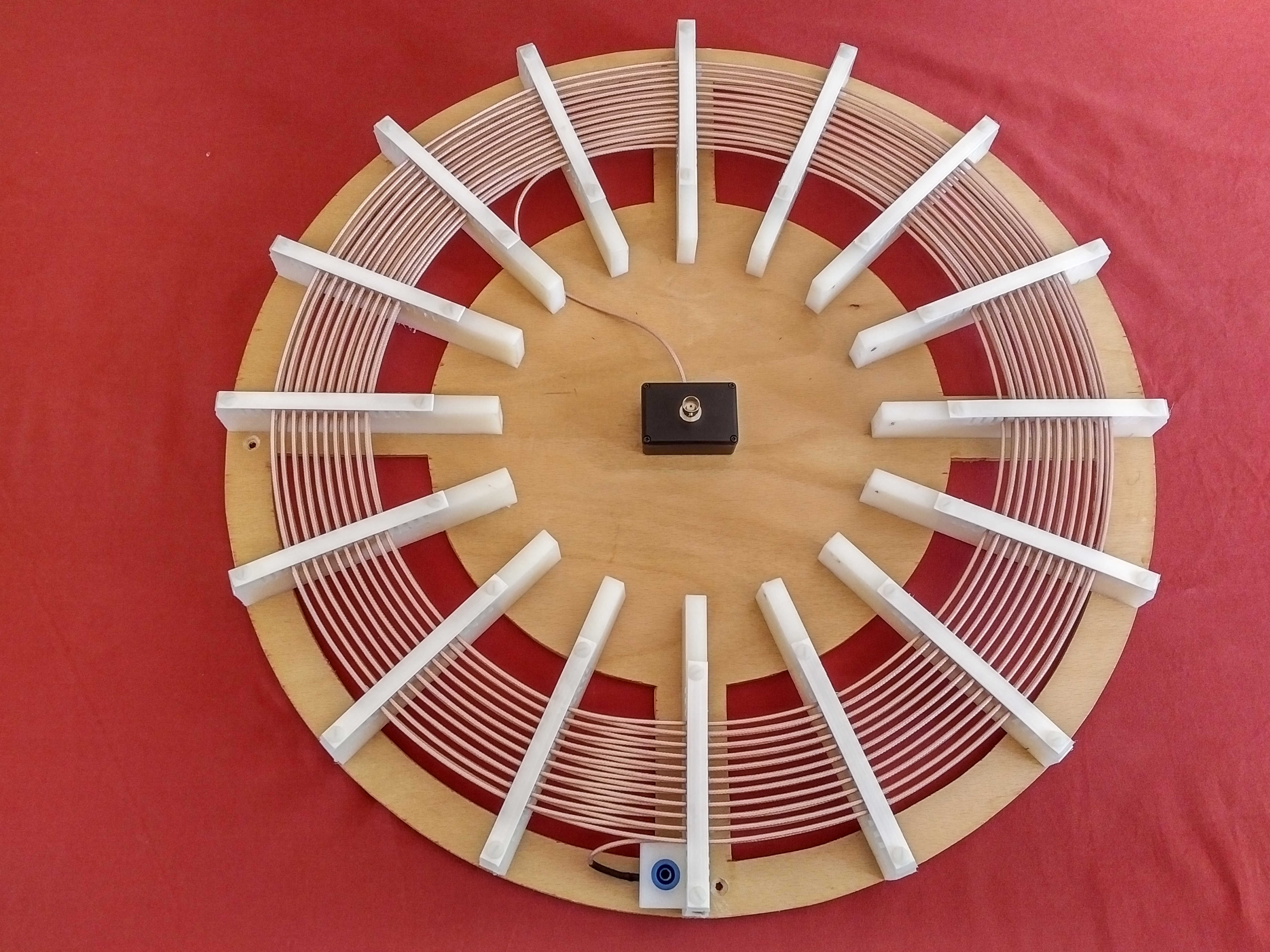
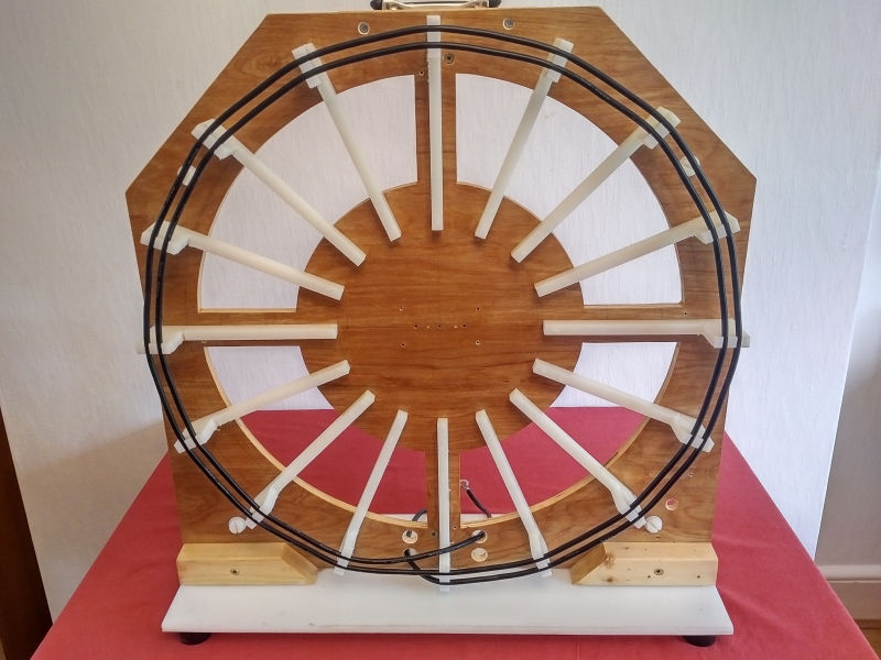
The flat coil design has provided the necessary dimensions and materials for the secondary and primary coil to be constructed. This post will outline construction of the 3S-1P flat coil described in Part 3 of the design. The complete constructed flat coil is shown in Figures 1. below, and gives an overall impression of how the coil has been mechanically designed to accommodate the required electrical coil design for a range of different experimental scenarios.


The overall required specification from the design process is summarised as follows, and can then be considered for the mechanical design and construction:
Secondary specification (3S):
Geometry: 2 spiral coils interleaved per turn
Number of turns: 20
Coil Inner diameter: 345mm
Coil Outer diameter: 455mm
Wire length: 25.132m
Wire type: RG316 braided coax with the outer braid connected only
Calculated inductance (assuming solid wire): 142.8µH
Primary specification (1P):
Geometry: spiral turns in same plane and outside the secondary
Number of turns: 2
Coil inner diameter: 525mm
Coil outer diameter: 575mm
Calculated wire length: 3.455m
Wire type: AWG10 1050 / 40 Silicone coated micro-stranded wire
Calculated wire length to equal primary and secondary conductor weight: 3.50m (2% error from calculated wire length to allow for 2 complete turns and connection)
Calculated inductance (assuming solid wire): 4.8µH
Frequency specification:
Secondary resonant frequency 180° phase change: 2400kc/s
Secondary tuned fundamental resonant frequency: 1810 – 2000kc/s
Calculated parallel primary tuning capacitance to match the secondary 180° phase change frequency: 916pF (assuming 4.8µH primary inductance)
Ideal parallel primary tuning capacitance: 100pF – 1200pF 4kV vacuum capacitor
Fig. 2. below shows the plan for the flat coil mechanical design with the key supports, secondary, and primary coil positions and dimensions indicated.

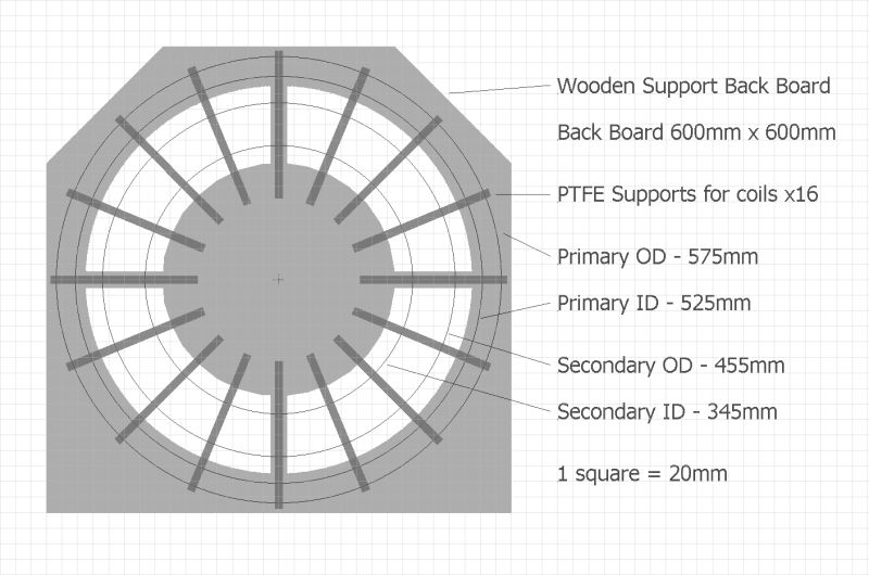
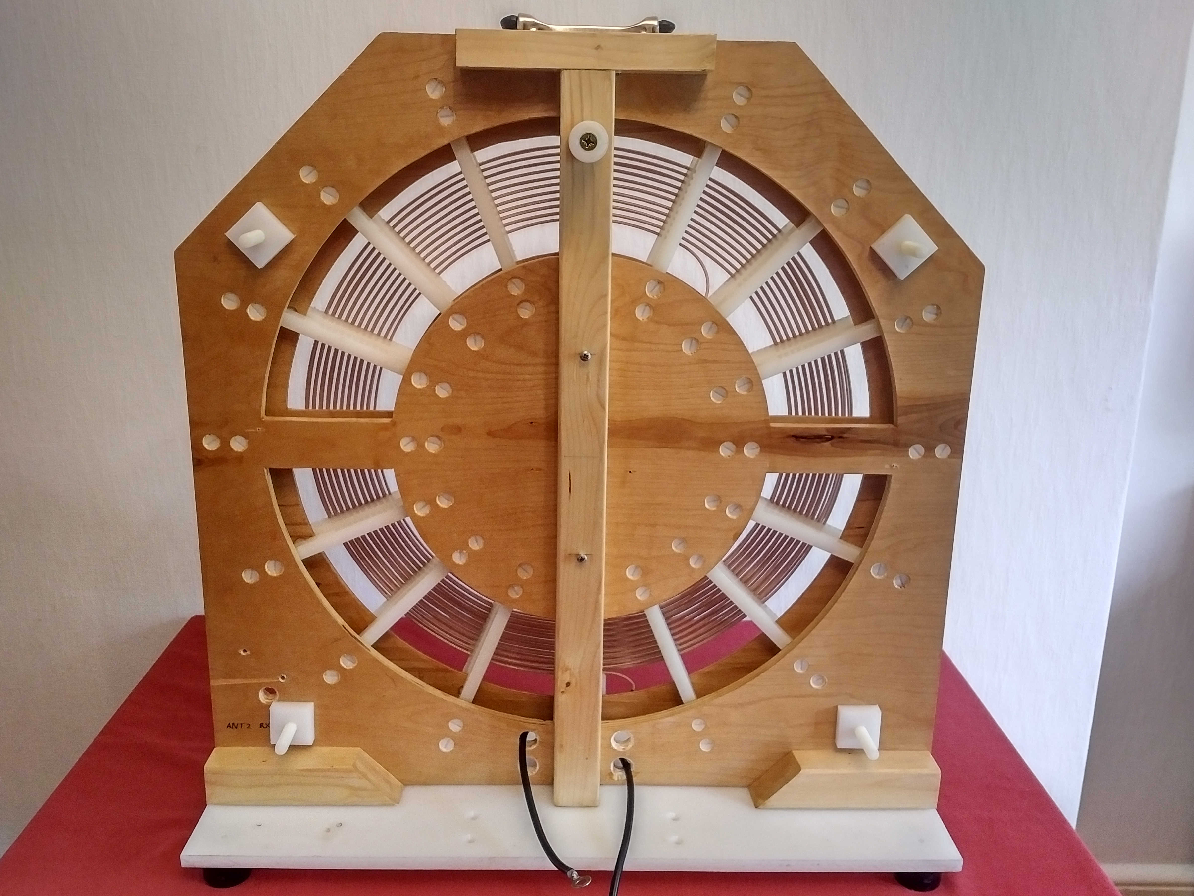
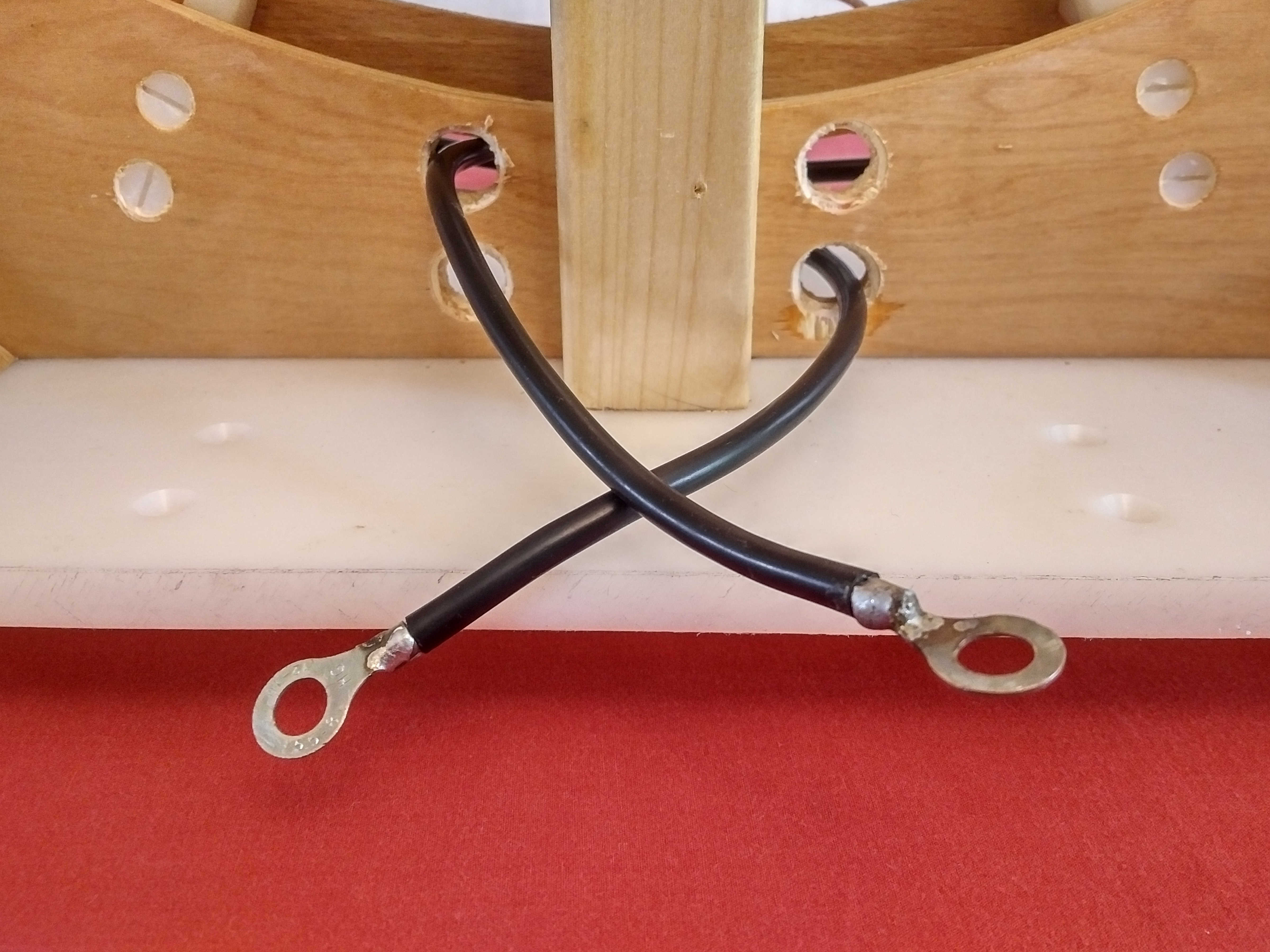
The back board uses 12mm thick finished interior plywood, and has four quarter circle cut-outs to remove the excess material from around the secondary coil. The back board is supported on a plywood or nylon base with a support pillar in the back to prevent warping of the plywood back board over time. It is useful to varnish the back board if the coil is to be used outside, to afford some protection against moisture absorption into the wood.
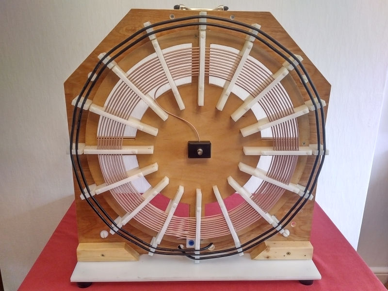
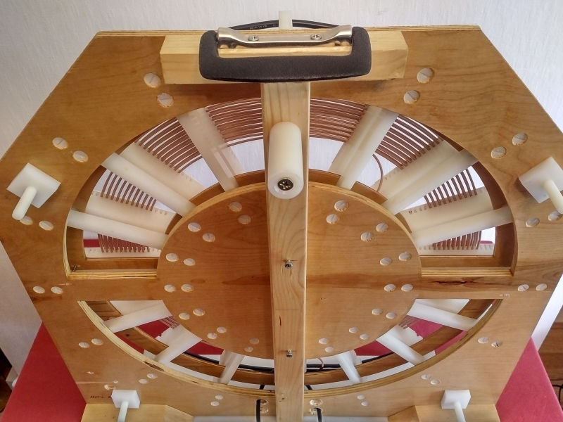
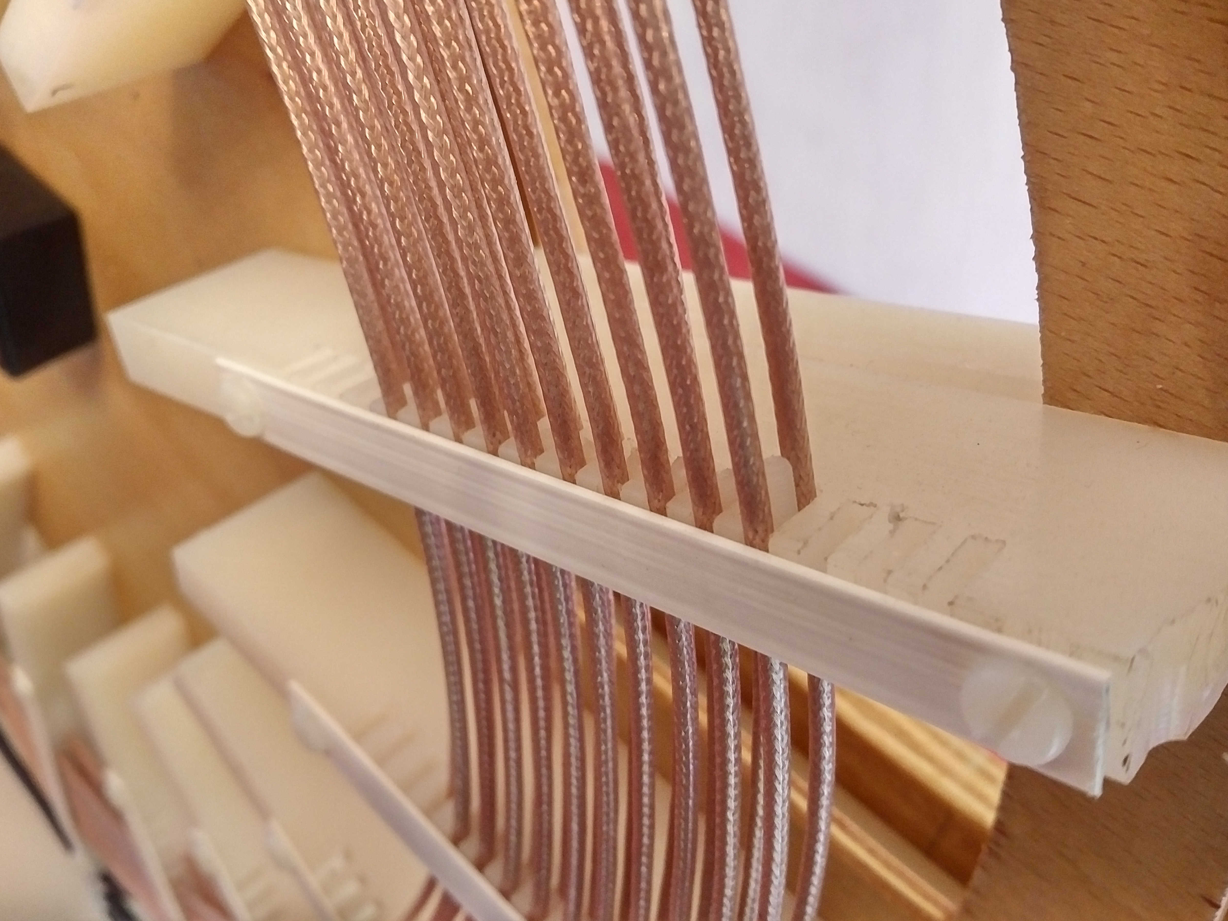
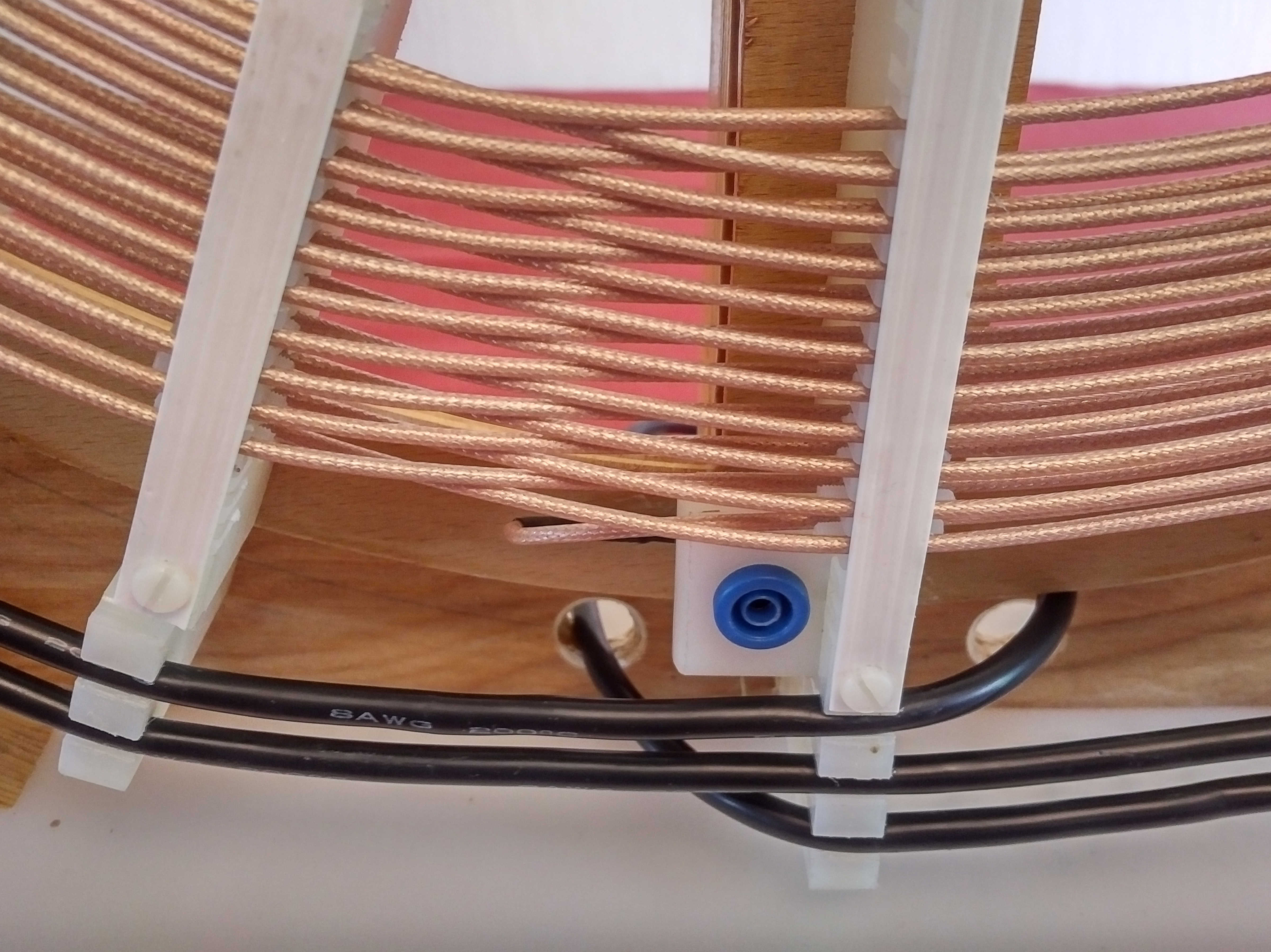
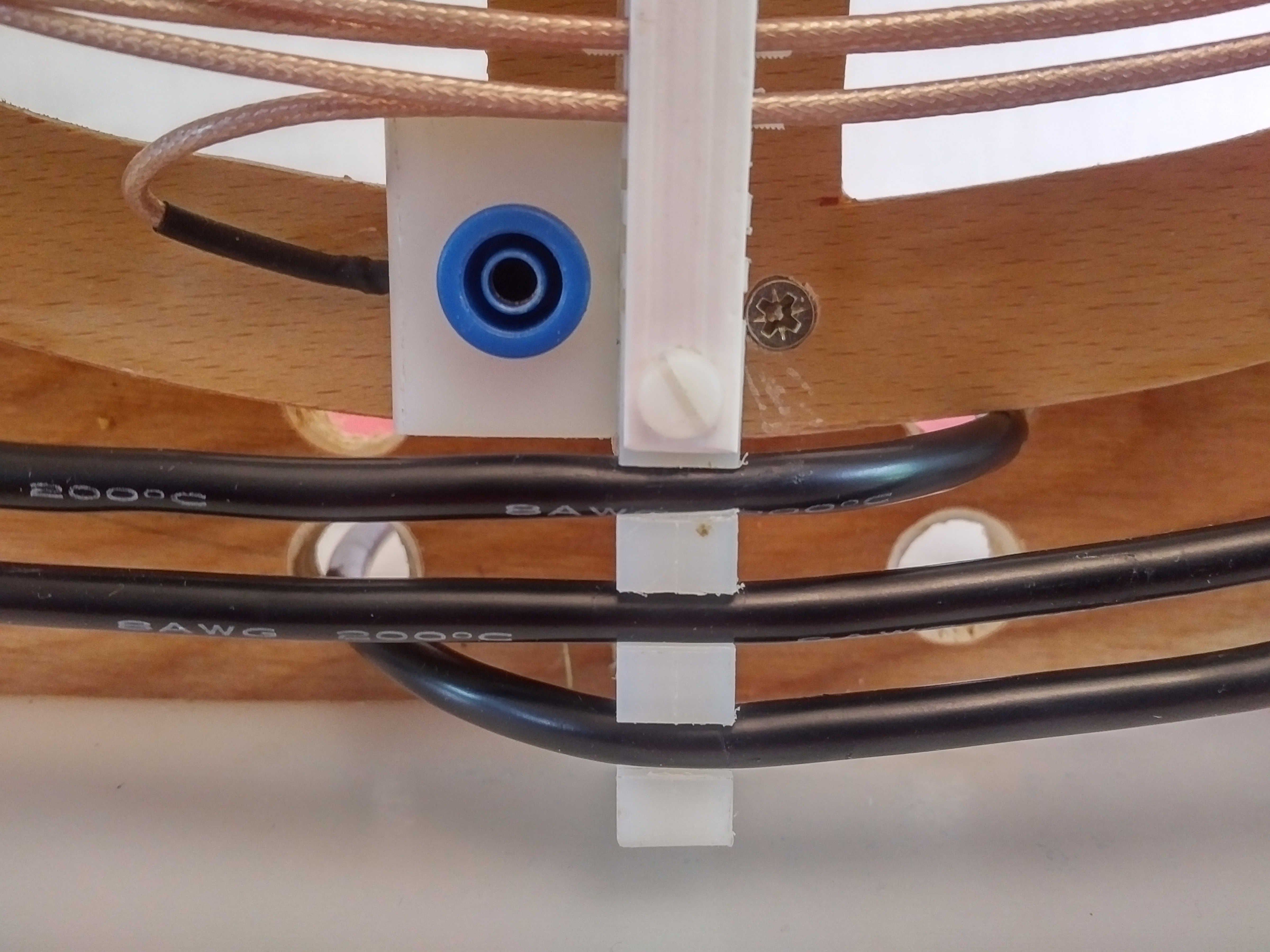
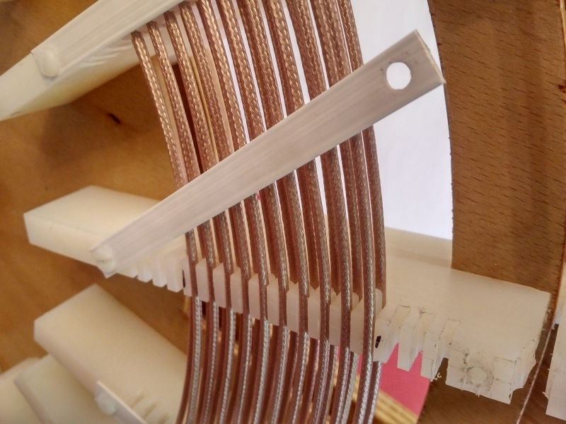
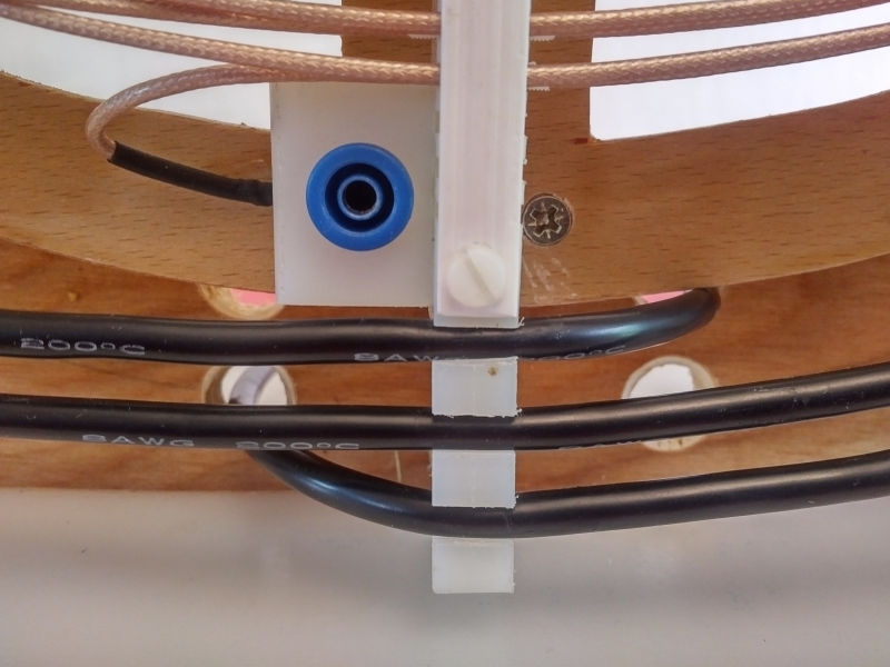
The coils are supported on the back board by 16 PTFE or Neutral Nylon 66 supports and have the dimensions 190mm x 50mm x 12mm (LxHxW). These supports have 2.5mm wide grooves cut 9.0mm deep from the top edge to retain the windings of the secondary coil. Three grooves where also cut outside of the secondary ID and OD to allow for rewinding adjustments during experimentation. In total 17 grooves (11 for the secondary and 3 either side) were cut to accommodate the windings of the secondary coil. The windings of the secondary coil are retained in the slots by sprung nylon straps screwed to the coil supports using tapped M3 nylon screws. This method of retaining the secondary was used rather than a more permanent gluing approach, to allow the windings to be adjusted, rewound, or even changed in specification or wire type if required. The coil supports were mounted to the back board using M6 countersunk nylon screws. No metal screws or attachments were used in close proximity to the coils.
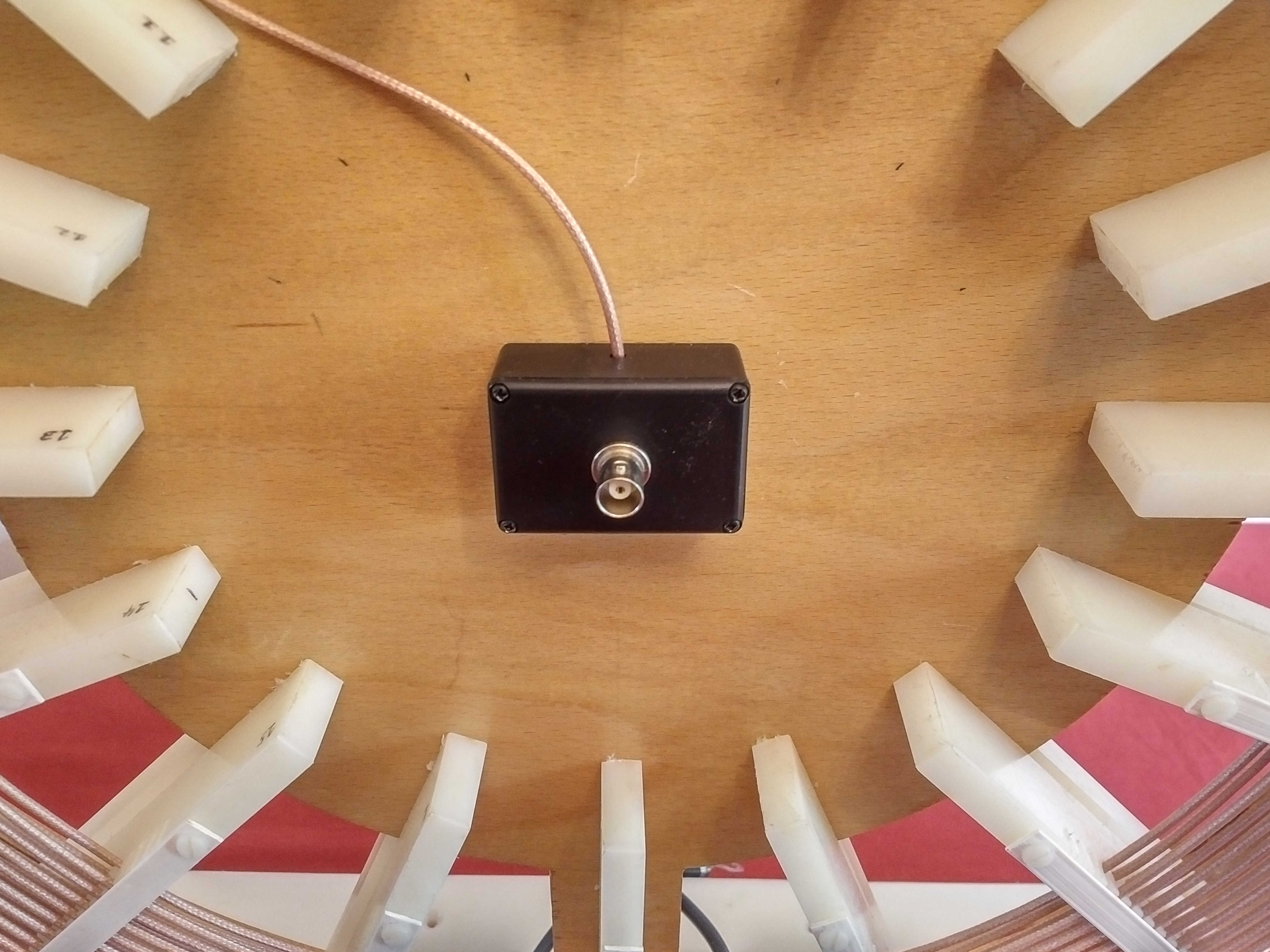
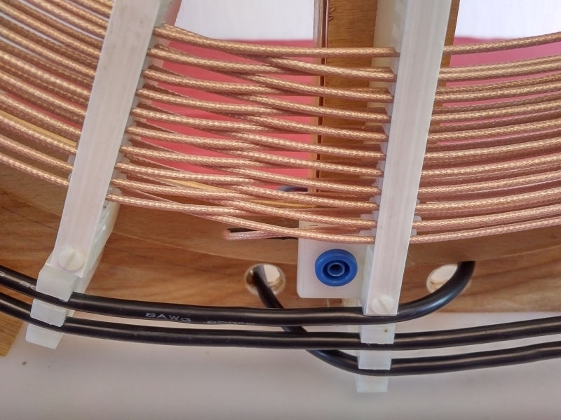
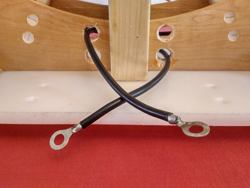
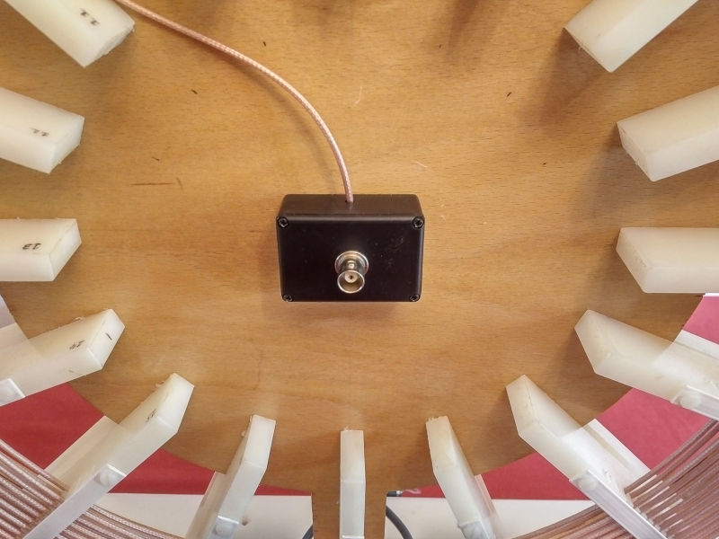
The outer top ends of the coil supports have an additional 3 x 6.0mm grooves cut 8mm deep to accommodate the windings of the primary wire. In addition each of the primary grooves was cut with a thin narrow slot (1mm wide) and 20mm deep to accommodate the flat copper strip primary (3P) if required. The bottom most coil support has a nylon mount for a high voltage output terminal connected to the outer end of the secondary coil. The inner end of the secondary conductor can be fed to a range of different mounts including a BNC connector for a telescopic aerial, a ceramic bulb-holder mounted on a nylon support for a neon bulb, or other high voltage terminal, feed, or top-load. The primary coil ends are fed through the back board, (via insulated conduits if necessary), and then attached directly to the primary capacitor at the primary length established in the equal weight of copper calculations in the part 3 of the design.
The early versions of the flat coil used solid nylon coil supports fixing the secondary and primary onto the back board. A later version of the flat coil, (as shown in the Figures 1. and 3.), used two-part coil supports arranged in such a way that the complete secondary unit can be removed from the primary and back board. This mechanical design greatly assists measurements of the secondary and primary independently whilst still in-situ to the experiment or circuit being measured. In the frequency measurements it is desirable to remove the secondary coil from the system and test the primary properties before adding the secondary, which then provides a much clearer understanding of how the two coils interact in the electrical system.
The secondary windings and the primary windings are normally wound in the same rotation direction on a single flat coil. A clockwise wound secondary will have a corresponding clockwise wound primary. For experiments involving displacement and transference of electric power between two flat coils the coil winding direction would ordinarily be in counter-rotation between the two flat coils, so as to define a clear boundary for the electric and magnetic fields of induction between the two coils. For example, if the flat coil attached to the generator has its windings wound clockwise, then the flat coil attached to the load will have its windings wound anti-clockwise. The flat coil winding possibilities have been measured, and the differences noted, for first, two flat coils counter wound, then secondly two flat coils wound in the same direction, and thirdly even with a single flat coil with counter-wound secondary and primary coils. These differences and their effects on the boundary conditions for the electric and magnetic fields of induction will be reported and considered in the measurement and experimental posts.
The secondary winding was wound onto the coil supports to create two inter-leaved coils as suggested and demonstrated by Dollard[1]. The lower turn is wound into the bottom of the coil support groove starting from the required secondary OD position. After the first complete turn nylon supports, fashioned from trimmed nylon M3 screws, were inserted into the groove to provide the correct spacing between the upper and lower coils. The depth of the groove and the spacer were so arranged so that the spacing between the two coils was ~60-65% of the conductor winding pitch. It has been suggested by Dollard[2] that this winding space is optimal for the inter-winding capacitive network and hence advantageous in generating the Longitudinal Magneto Dielectric (LMD) wave or standing wave. The formation of the LMD wave is conjectured as a necessary pre-condition for the generation of a displacement event when combined with a non-linear element, load, or event in the system.
To investigate and confirm the 60-65% spacing, a flat coil has also been assembled where the upper and lower coils are wound directly on top of each other with no nylon spacer, and only spaced by twice the thickness of the insulating jacket around the conductor of the winding. In the case of the 3S coax braid coil the conductors are spaced by 0.5mm without the nylon spacer, and by 3.0mm with the spacer. In the case of the 1S PTFE coated stranded wire the conductors are spaced by 1.0mm without the nylon spacer, and by 3.5mm with the spacer.
With the spacer in place above the lower winding the upper turn is now added to the coil. When one complete turn has been wound the wire in the upper coil will move to the lower coil in the next adjacent groove of the coil support. This continues until 10 complete grooves have been wound, which corresponds to an inter-leaved upper and lower flat coil of 10 turns each, and 20 turns in total. After the 10 complete grooves have been wound the coil length can be fine adjusted by a fraction of a turn (e.g. 0.5) before being terminated at the conductor centre mount.
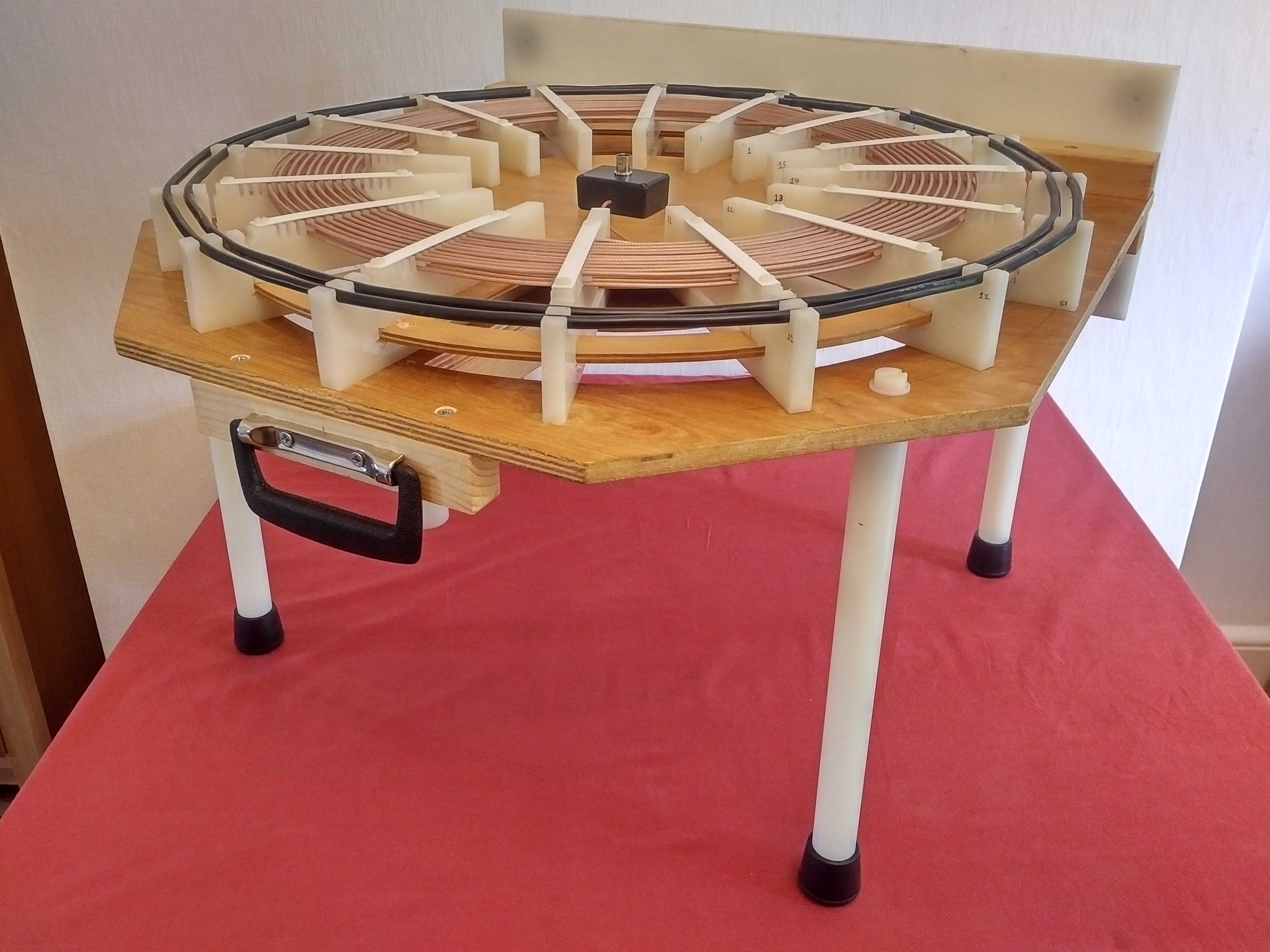
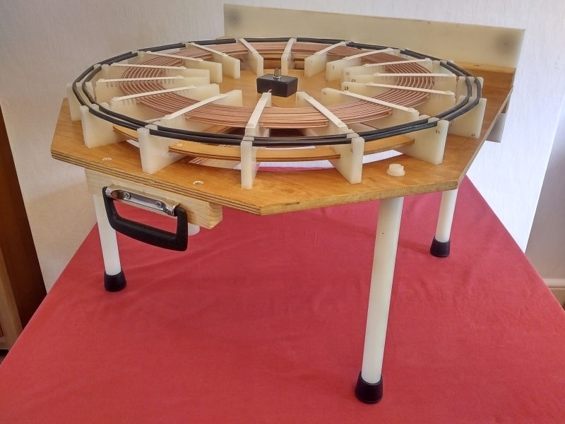
In later versions of the flat coil the back-board was modified to provide mounts for using the coil vertically, horizontally, or with nylon threaded mounts to attach legs so that the coil can be used horizontally outside or on the bench. This combination of fixtures allow for a wide range of experimental conditions including outside as well as inside in the lab or workshop.
Detailed pictures of the mechanical construction are shown in Figures 3. below.


Click here to continue to the flat coil frequency measurements part 1.
1. Dollard, E. & Lindemann, P. & Brown, T., Tesla’s Longitudinal Electricity, Borderland Sciences Video, 1987.
2. Dollard, E., Theory of Wireless Power, Borderland Sciences Publication, 1986.
3. A & P Electronic Media, AMInnovations by Adrian Marsh, 2019, EMediaPress