


In this second post on the Tube Power Supply series I present a complete design and implementation of a high voltage (HV) unit suitable for use as a high-power plate supply, and also as a general purpose high-tension source for a wide range of experiments in electricity. I use this unit extensively in my own day-to-day research for experiments in the displacement and transference of electric power. The 5kW high voltage and plate supply is based around three heavy-duty industrial 1.8kVA microwave oven transformers which can easily be inter-connected in a range of different parallel and series configurations. The transformers can be easily combined with different output stages including a bridge rectifier, level shifter (doubler), and a high voltage discharge unit, which are all incorporated into the complete housing of the supply. The complete high voltage supply is housed in a traditional varnished wooden enclosure and is designed to fit together with the other supply components in the tube power supply series.
Note: A high voltage supply is capable of delivering voltages and currents, even at lower powers, that are instantly lethal, and that any design and operation of a high voltage unit should be undertaken with great care by a trained and experienced individual. The high-voltage supply presented in this post is intended for high-power electricity research experiments undertaken by trained and experienced operators only. The different transformer configurations combined with the different output stages make for a very versatile, robust, and adaptable high voltage and plate supply with a fully loaded output ranging from 2.1kVRMS @ ~ 2.3A all the way up to 15kVRMS @ ~ 150mA. This very wide output range currently accommodates all of the tube amplifiers, oscillators, and impulse generators that I use in my own research, including the following examples that are used in experiments presented, or yet to be presented, on this website:
1. A basic parallel connected quad 811A linear amplifier or Hartley power oscillator, using 1.2kV plate supply and producing about 1kW of sustained output power at frequencies up to ~4Mc.
2. A parallel connected dual 833C class-C Armstrong oscillator using a 4kV plate supply and producing up to 2.5kW of sustained output power at frequencies up to ~4.5Mc.
3. A single GU5B class-C Armstrong oscillator using a 4-5kV plate supply and producing up to 2kW of sustained output power up to ~3Mc, or even using a 9kV plate supply when used in pulsed-mode with a low duty cycle.
4. A dual push-pull connected 4-400A linear amplifier using 4kV plate supply and producing up to 1kW of power up to ~5Mc.
5. A dual 5C22 hydrogen thyratron pulse generator, with an anode supply up to 15kV.
Figure 1 below shows a summary table of the main setup configurations that can be arranged with the presented power supply, and the nominal outputs that can be achieved using that configuration, and with the various indicated output stages. These performance characteristics are presented as a guide to the configuration and usage of this high voltage supply, and may vary according to the type of load or generator being driven, the impedance match conditions between the supply and the generator and experiment, and also the type and condition of the transformers used in the supply build.

The following video takes a detailed look at the high voltage plate supply, its design, development, and implementation, how to configure and setup the required operation mode, the different output stages, the various safety requirements during its operation, and concluding with a demonstration of its operation during experiments in the Wheelwork of Nature series, when used with the single GU5B class-C Armstrong oscillator generator.
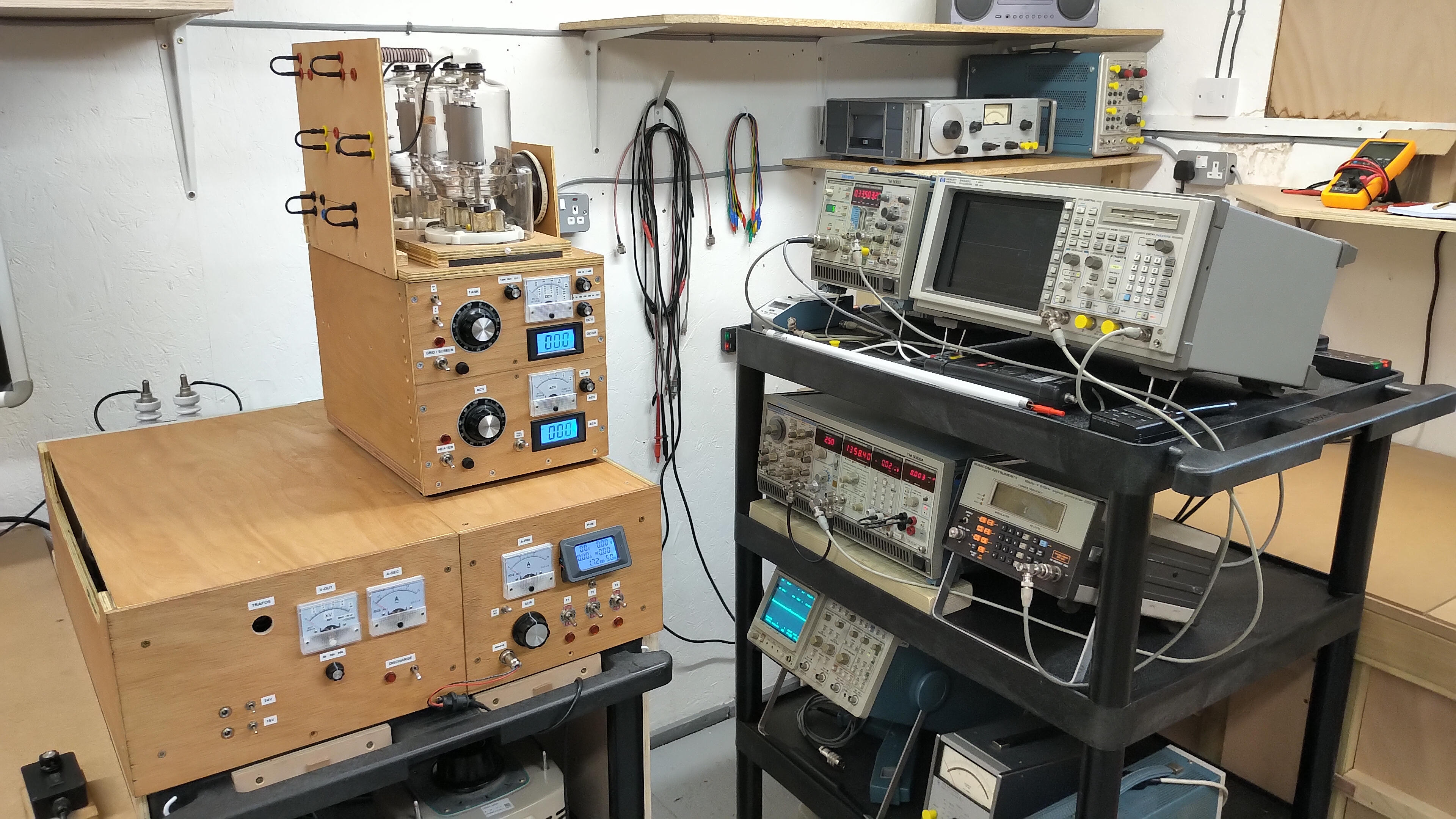
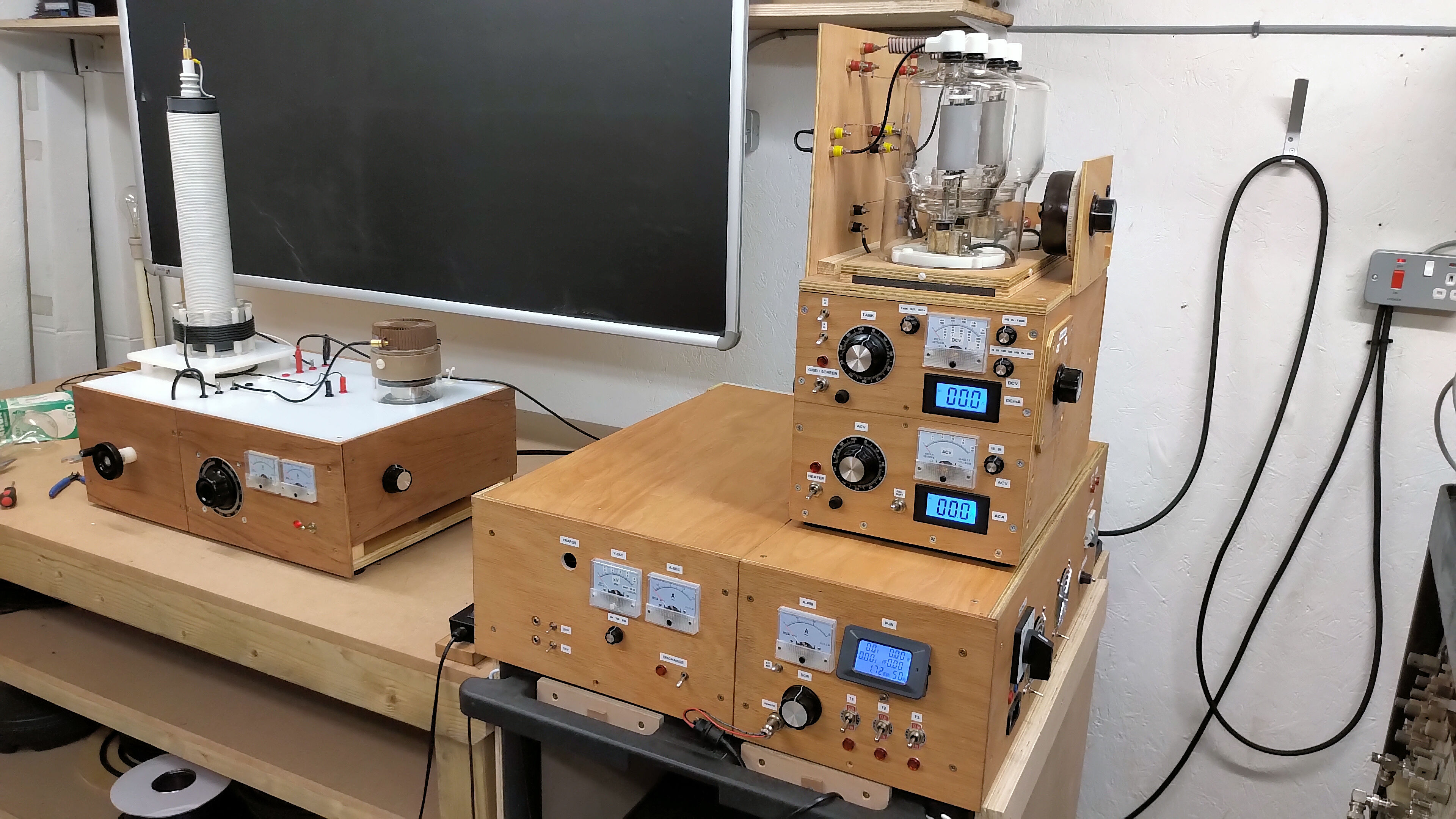
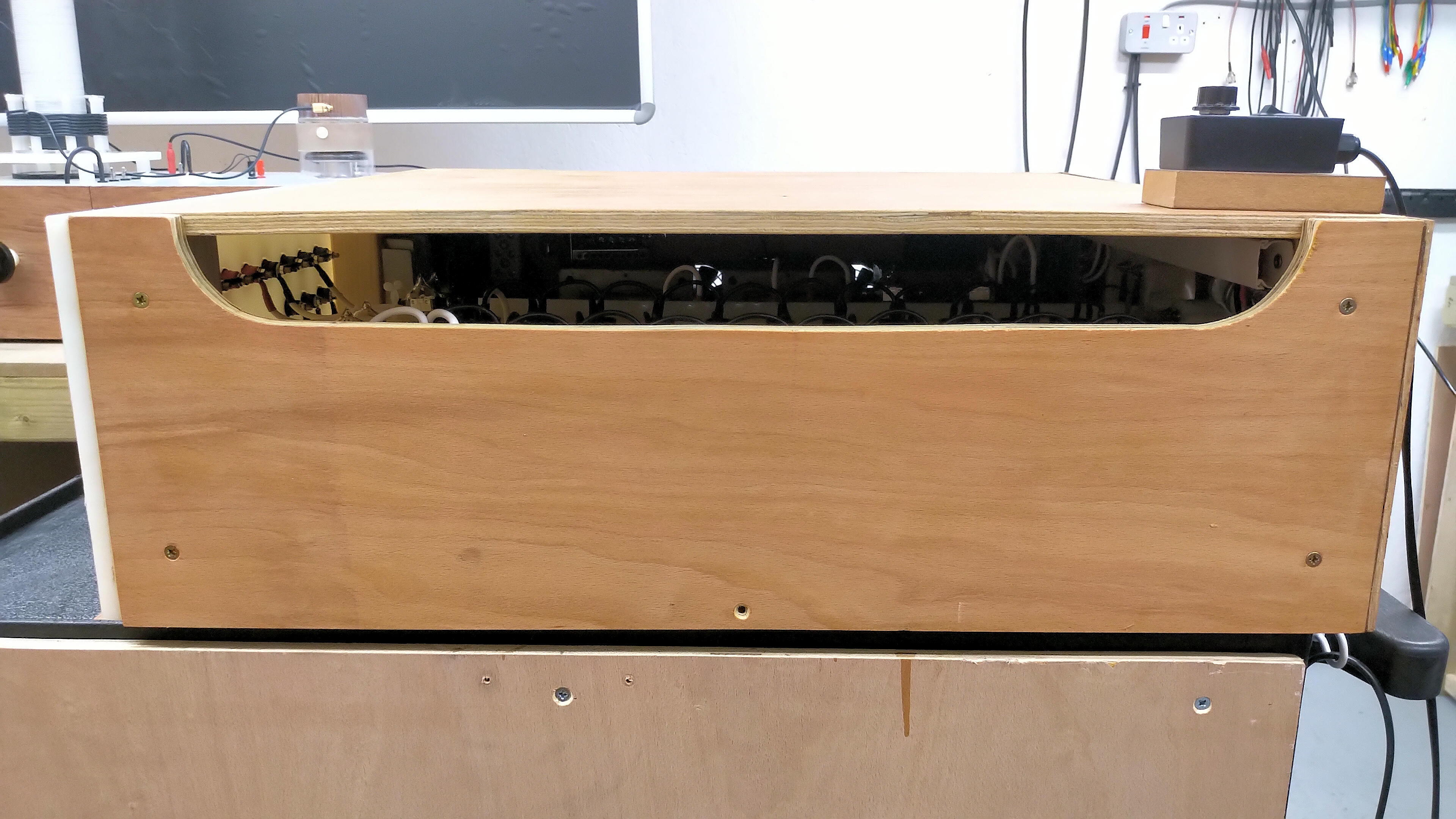
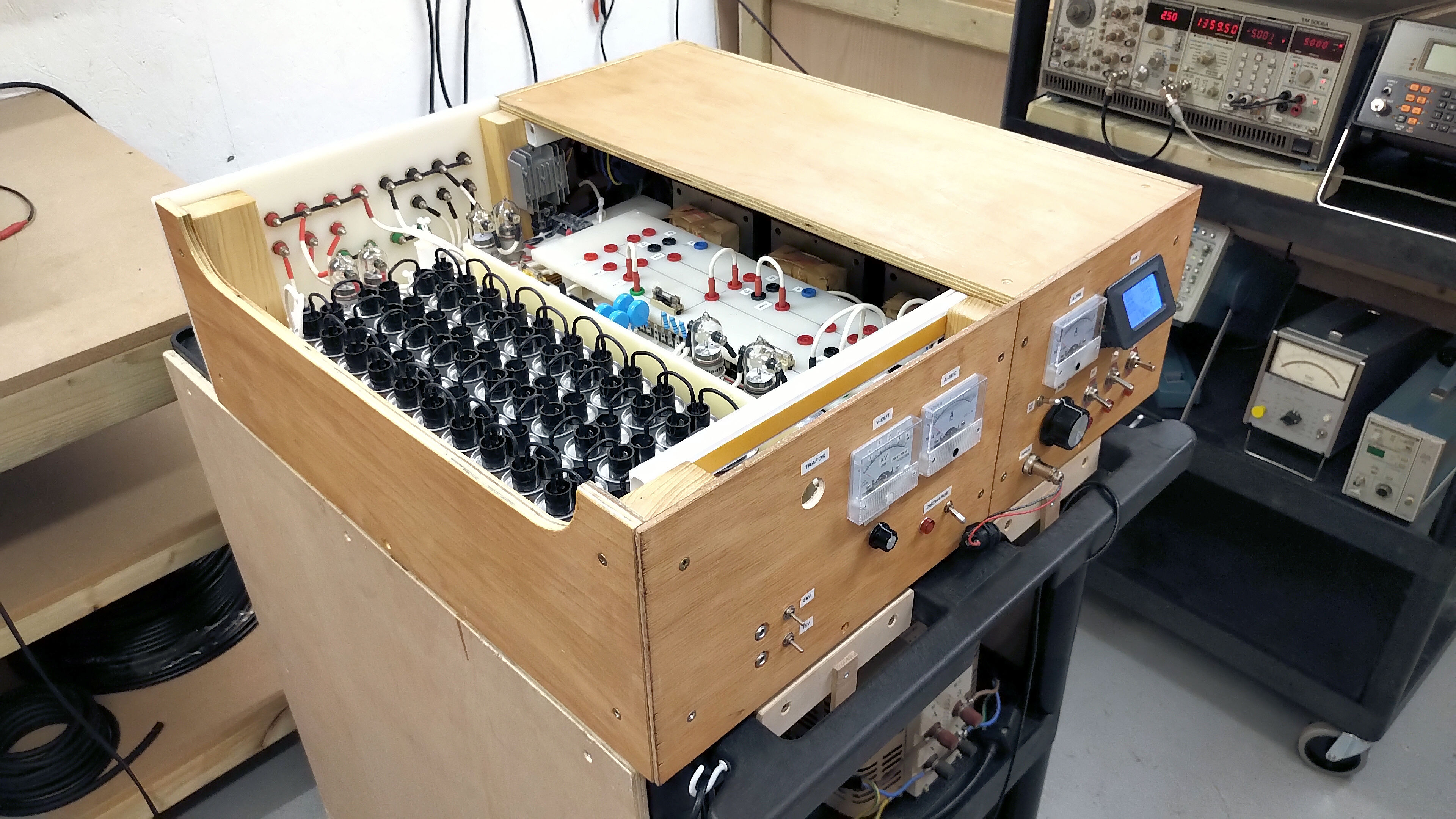
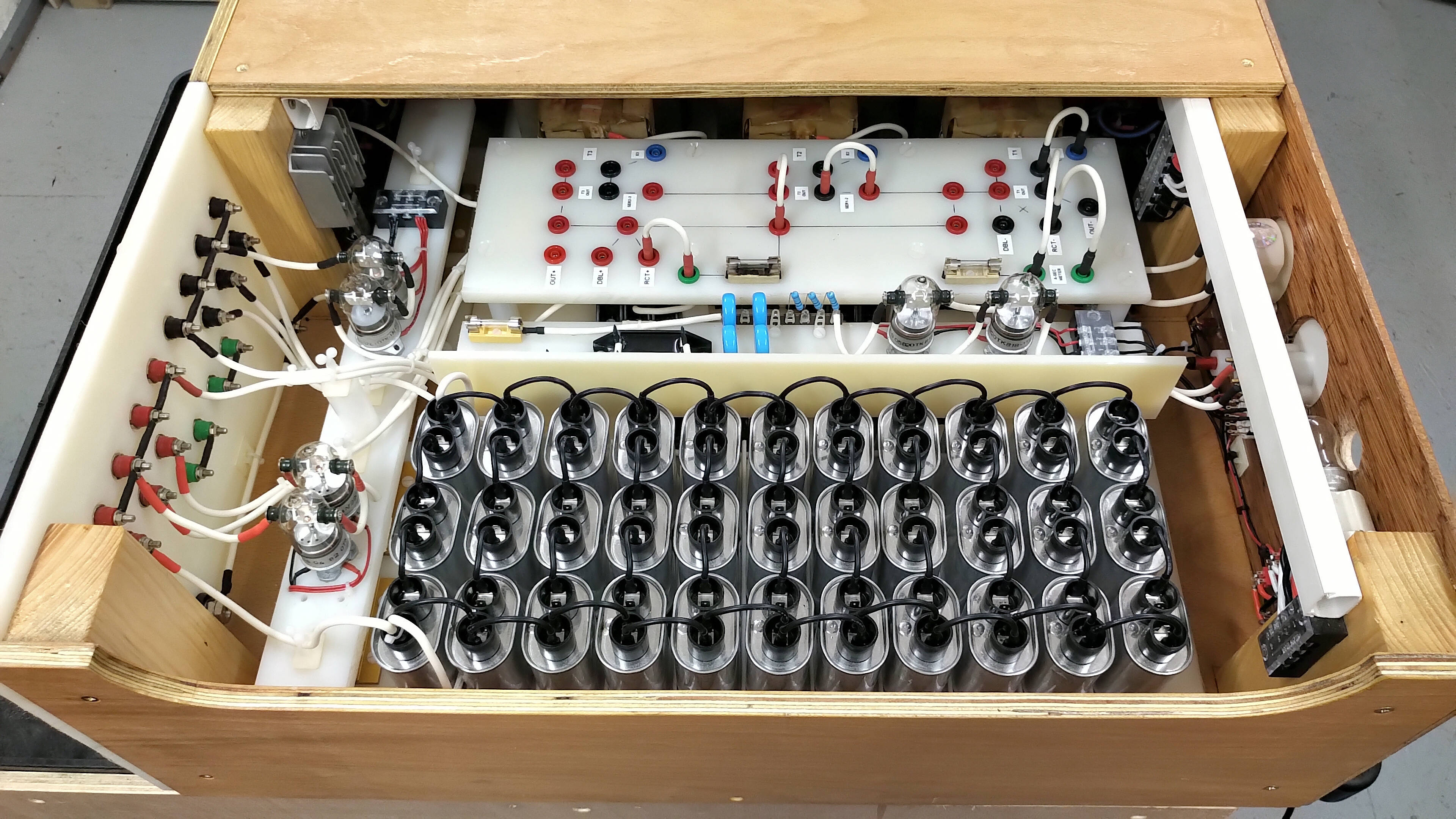
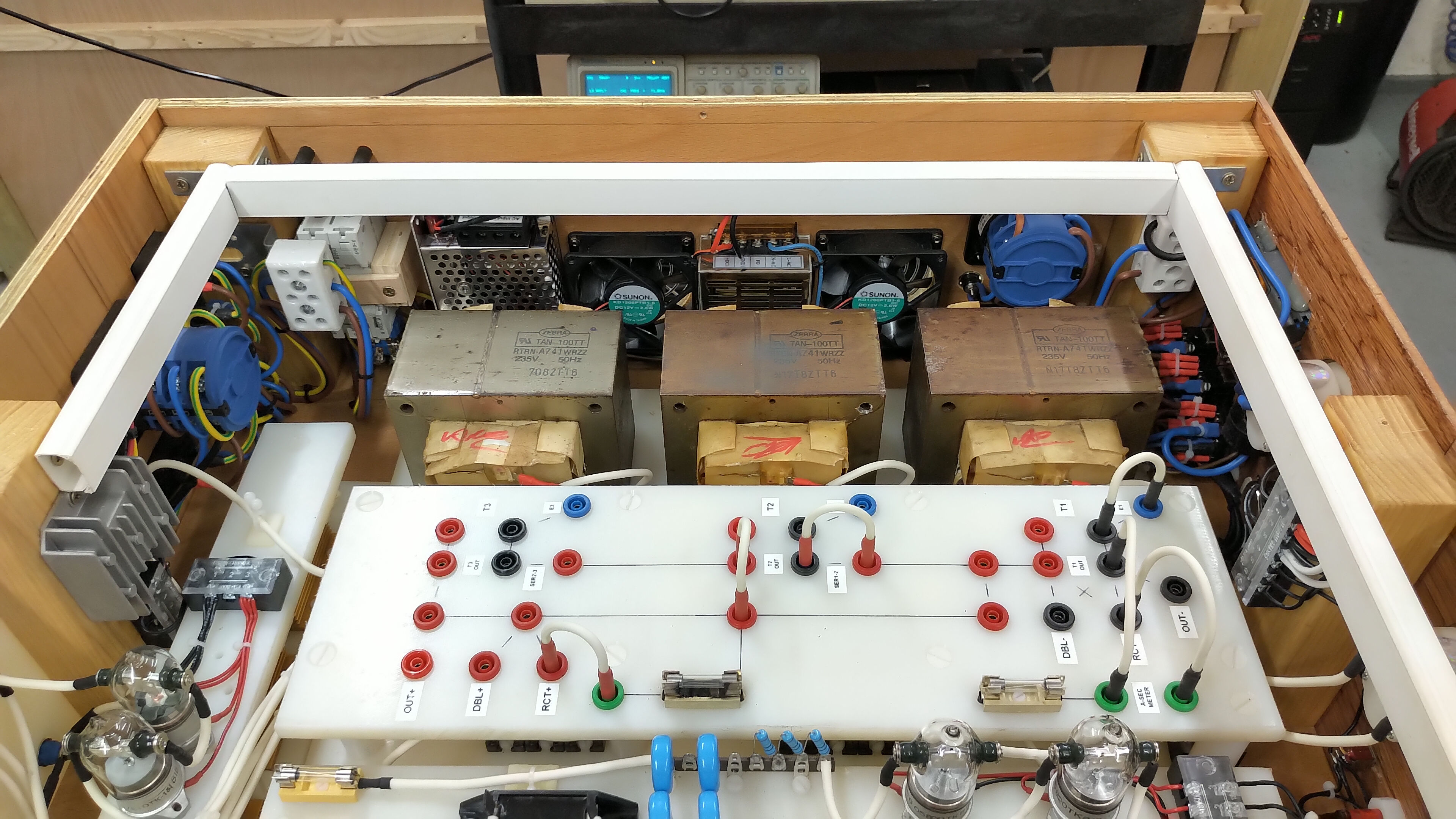
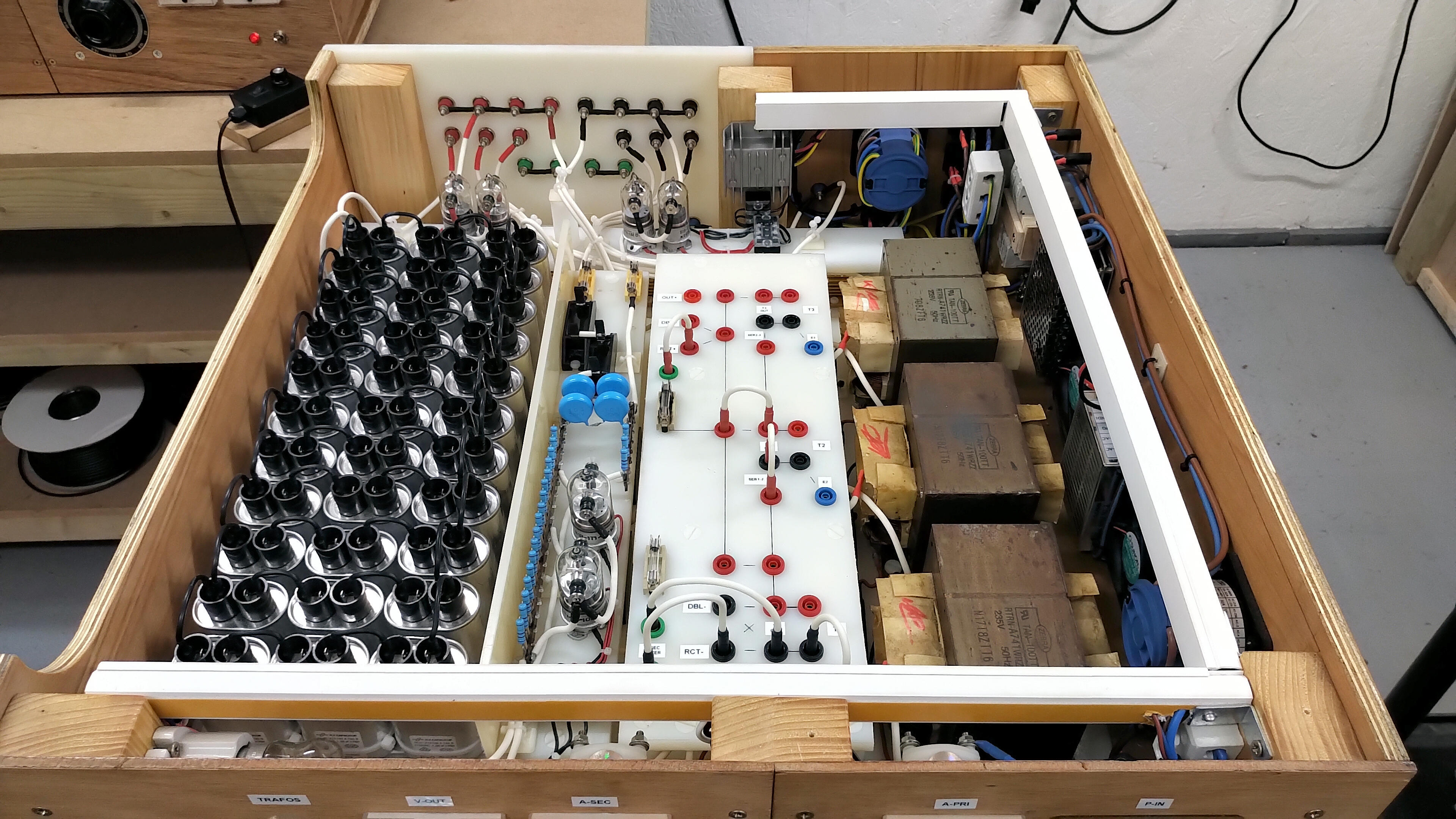
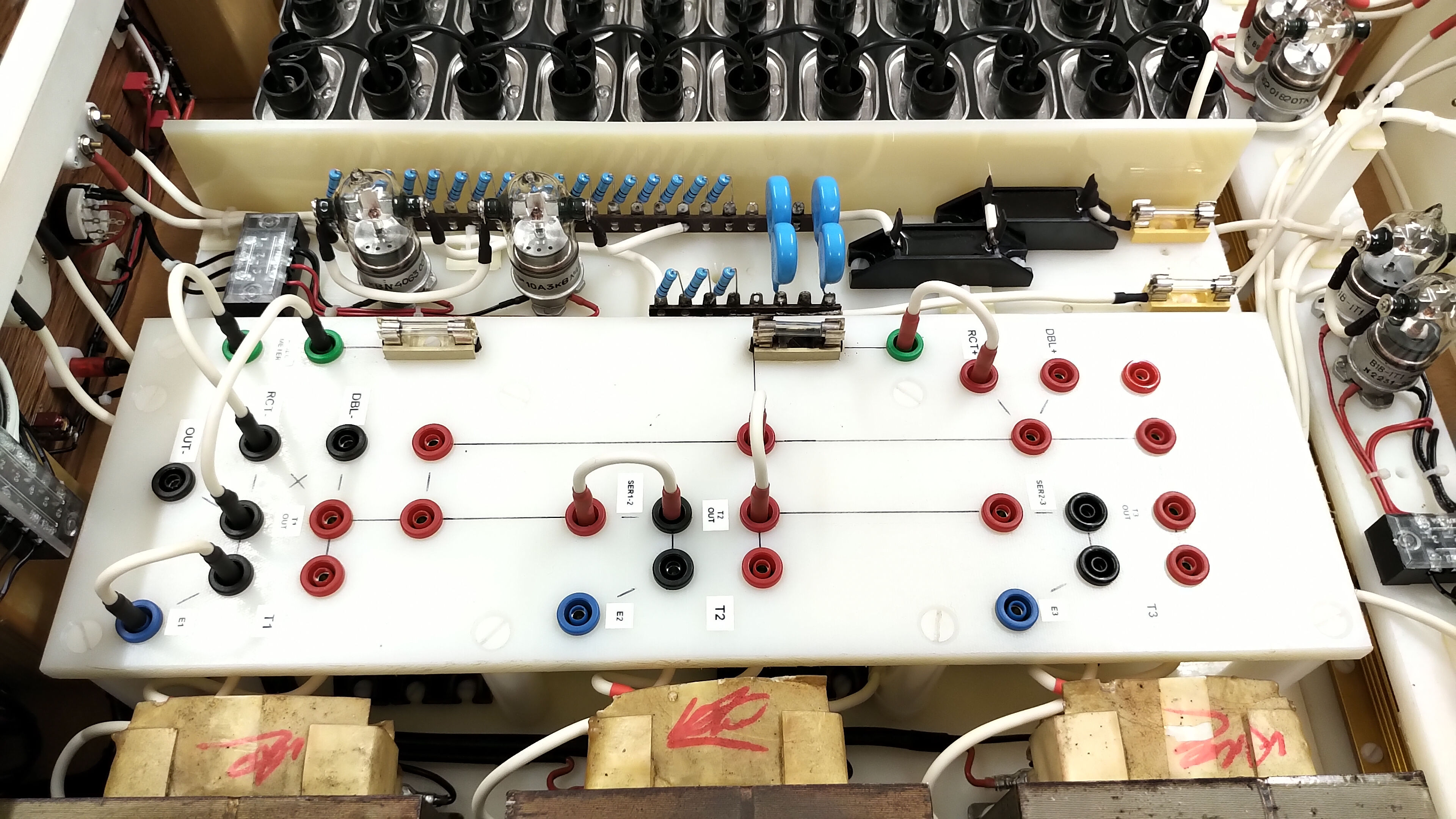
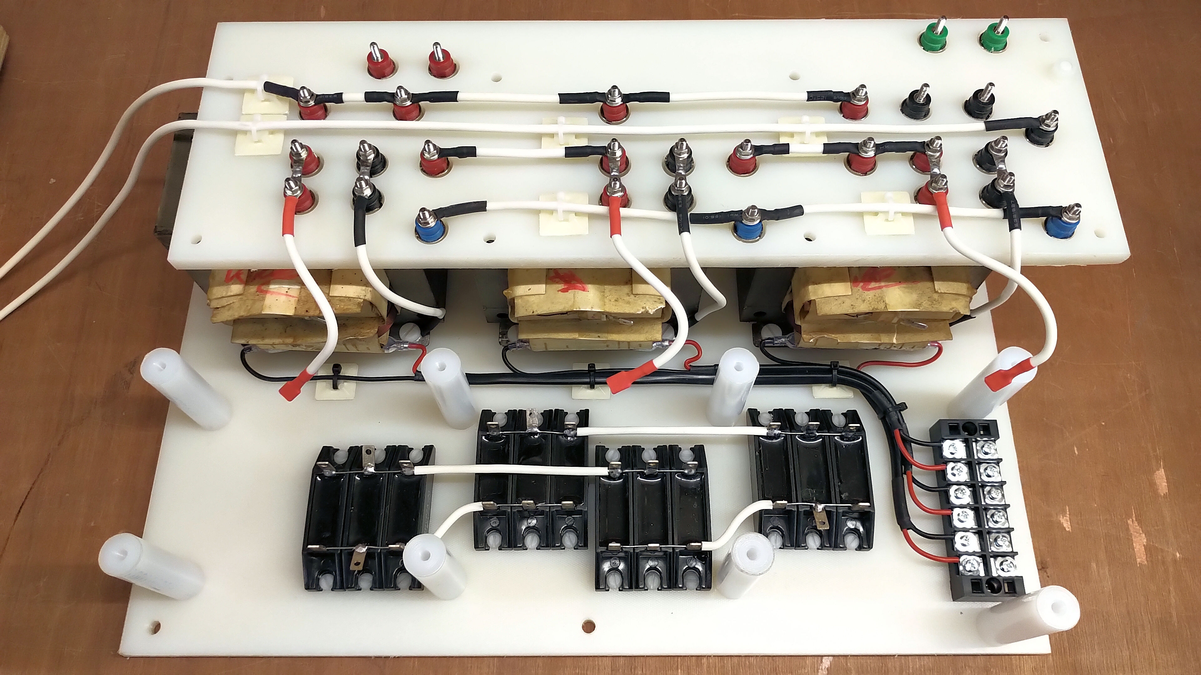
Figures 2 below show the high voltage and plate supply in detail both from the exterior panels and sides, through to the internal modular boards, layout, and construction.


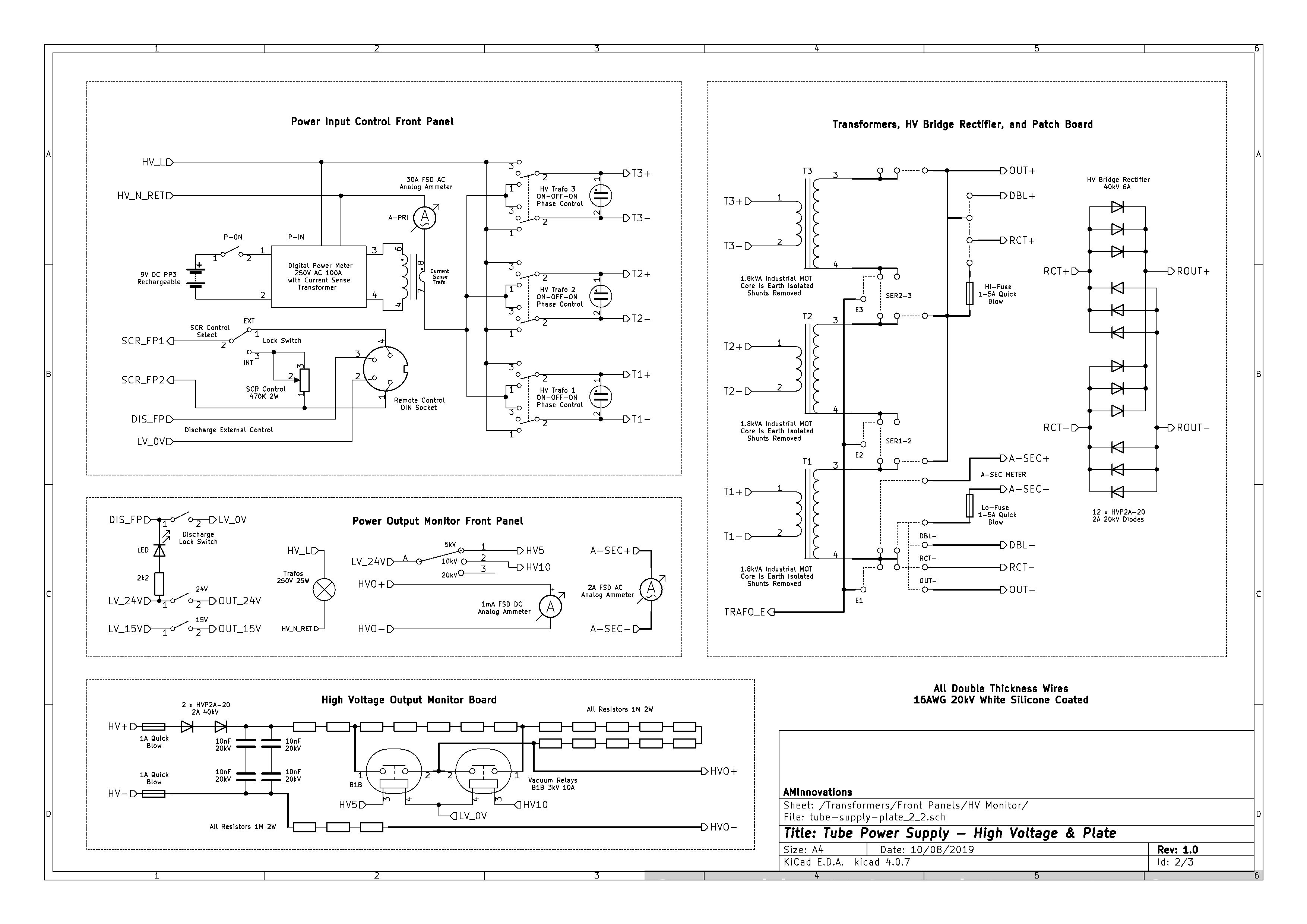
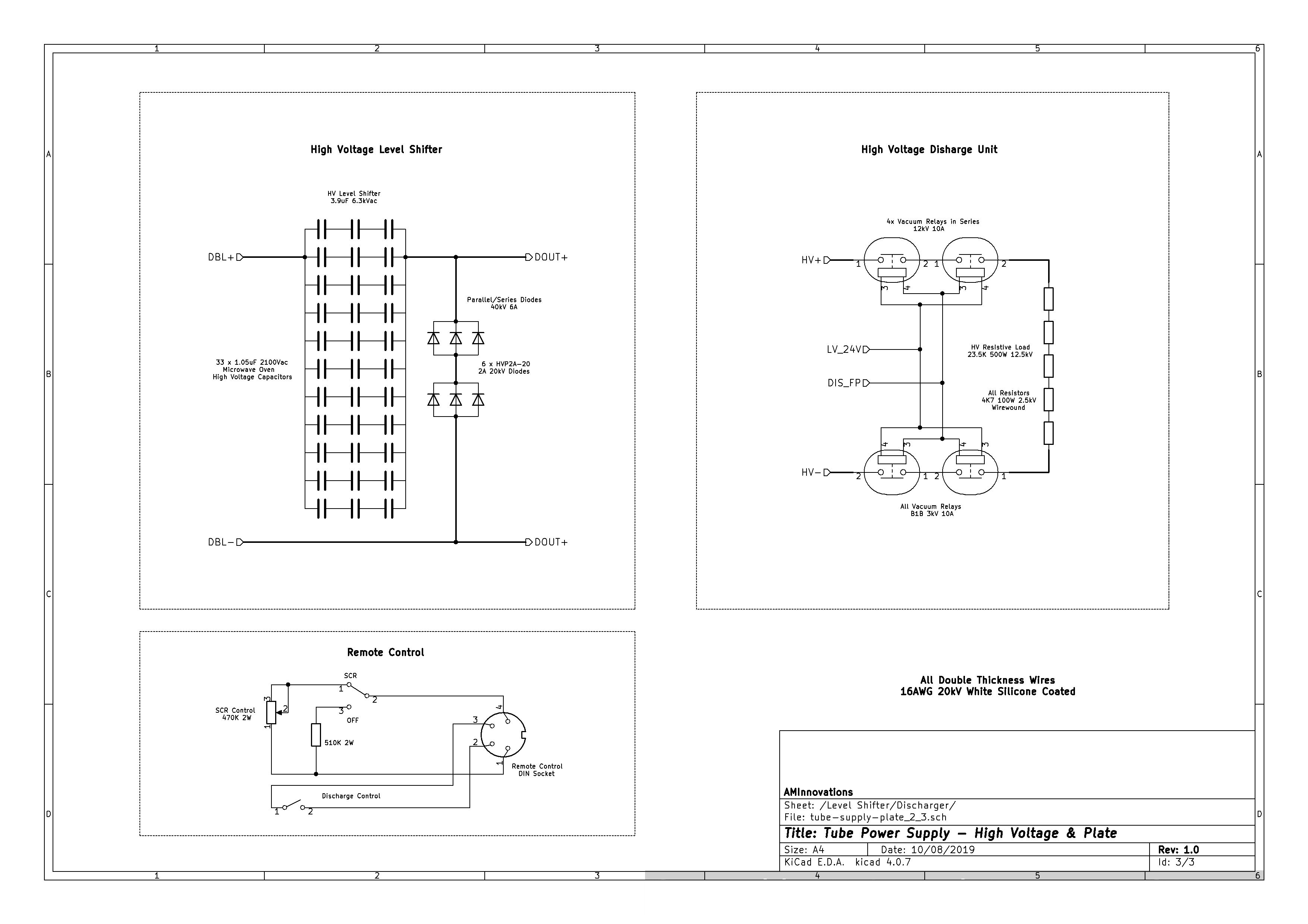
Figures 3 below show the complete circuit diagrams for the high voltage and plate supply across three sheets. The high-resolution versions can be viewed by clicking on the following links Fig 3.1, Fig 3.2, and Fig 3.3.


Principle of Operation – General Summary
In principle the plate supply is very simple consisting of three microwave oven transformers that can be easily connected in a variety of parallel and serial configurations. Power is provided to the transformers from the line supply and via a high power SCR control unit equivalent to a powerful light dimmer control, or from an external source such as a variac or other type of power controller. The selected line supply is then fed to the three transformer power switches on the front panel. These three position switches have a centre off position, and then on position either both up and down. The on positions are arranged to swap the live and neutral connections to the transformer so changing the phase of the line supply to each transformer. The change in phase of the line supply allows transformers to be configured in different arrangements both as positive and negative output with a centre ground point. This is particularly useful in the case of the three series transformers where maximum voltage from core to primary needs to be restricted. This is covered in detail in a later section below.
Phase controlled line supply is then fed from the front panel to the transformer board primary coil circuits. The patch board allows for configuration of the connections on the secondary coil side of the transformers. The output of the patch board feeds various different modules including direct output, the HV bridge rectifier, and the HV level shifter. The selected module is finally connected to the final high tension (HT) output via a second patch board on the HT rear output panel. The HT output is then also connected to the HV discharge board, and also to the HV output monitor board. The HT output board also provides intermediary connections for tank/blocking capacitors facilitating the series and parallel connection of large HV capacitors safely and in close proximity to the power supply outputs. The wooden enclosure is so arranged to accommodate other devices in the tube power supply series, as well as open access to the main components through a large access panel in the top of the plate supply. In extreme operating and prototype conditions I often run with this access panel open (and via remote control) in order to watch for any unusual or unexpected effects.
The complete supply is housed in a varnished wooden casing, and internally arranged and assembled to be easy to repair, maintain, and modify. Module boards can be easily removed internally, and side panels fold open whilst still electrically connected for easy measurement and fault diagnosis. It should be noted that this type of power supply is designed for research prototyping and hence encounters a very wide range of different loading and matching, all the way from an open circuit condition on the output, through to heavily overloaded current conditions, and very high reflected RF and transient power conditions. These extreme operating conditions necessitate that the power supply is easy to diagnose, adjust, and repair internally, and hence it is arranged and assembled accordingly with easy access to all critical internal systems.
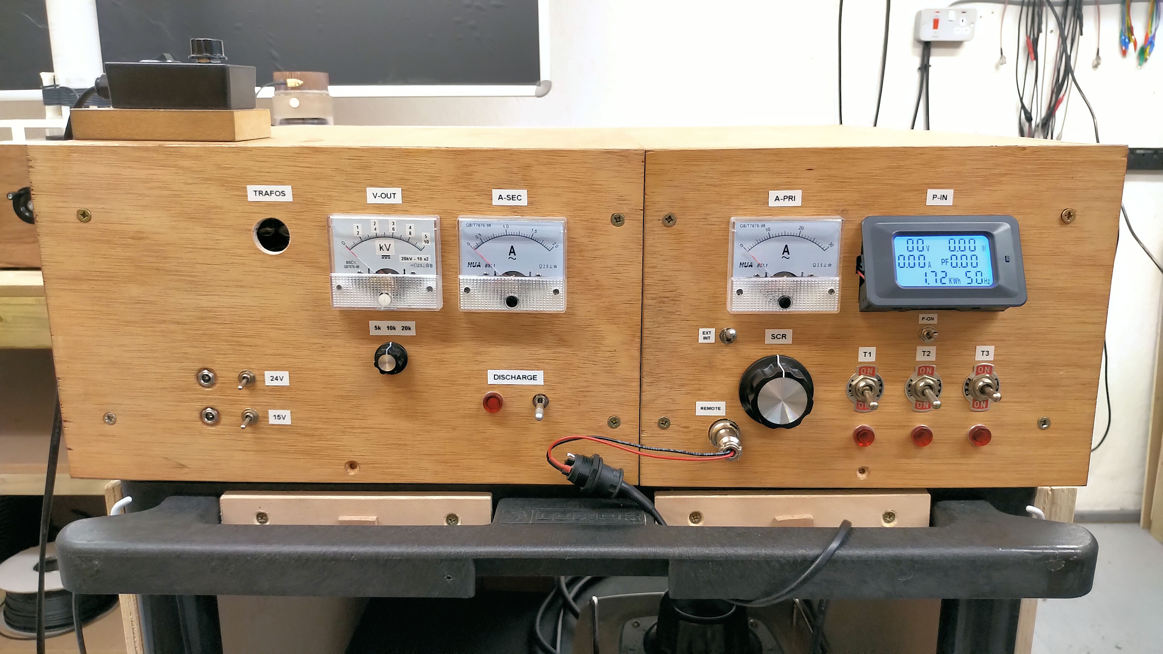
Power Input and Control Panel
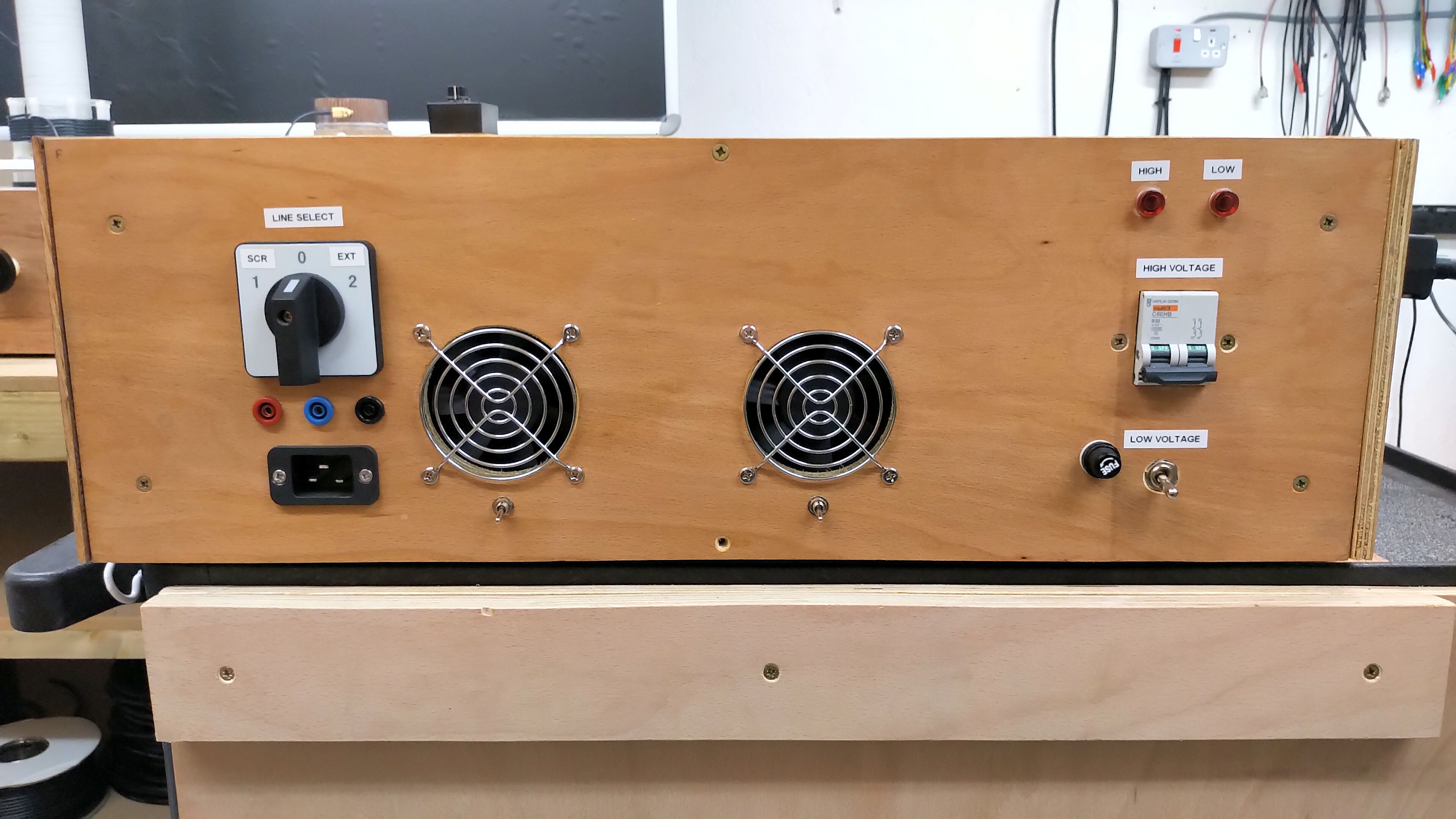
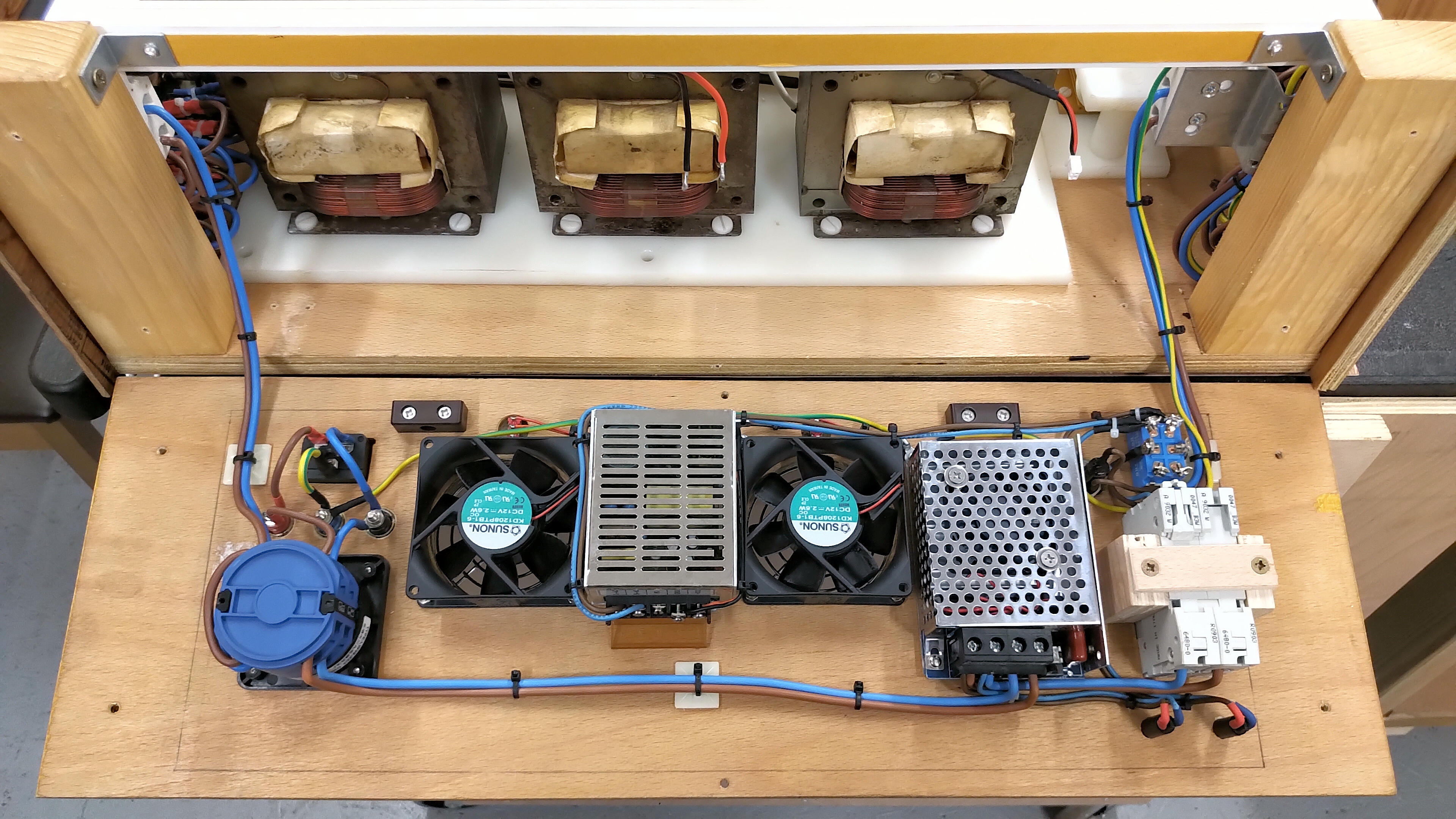
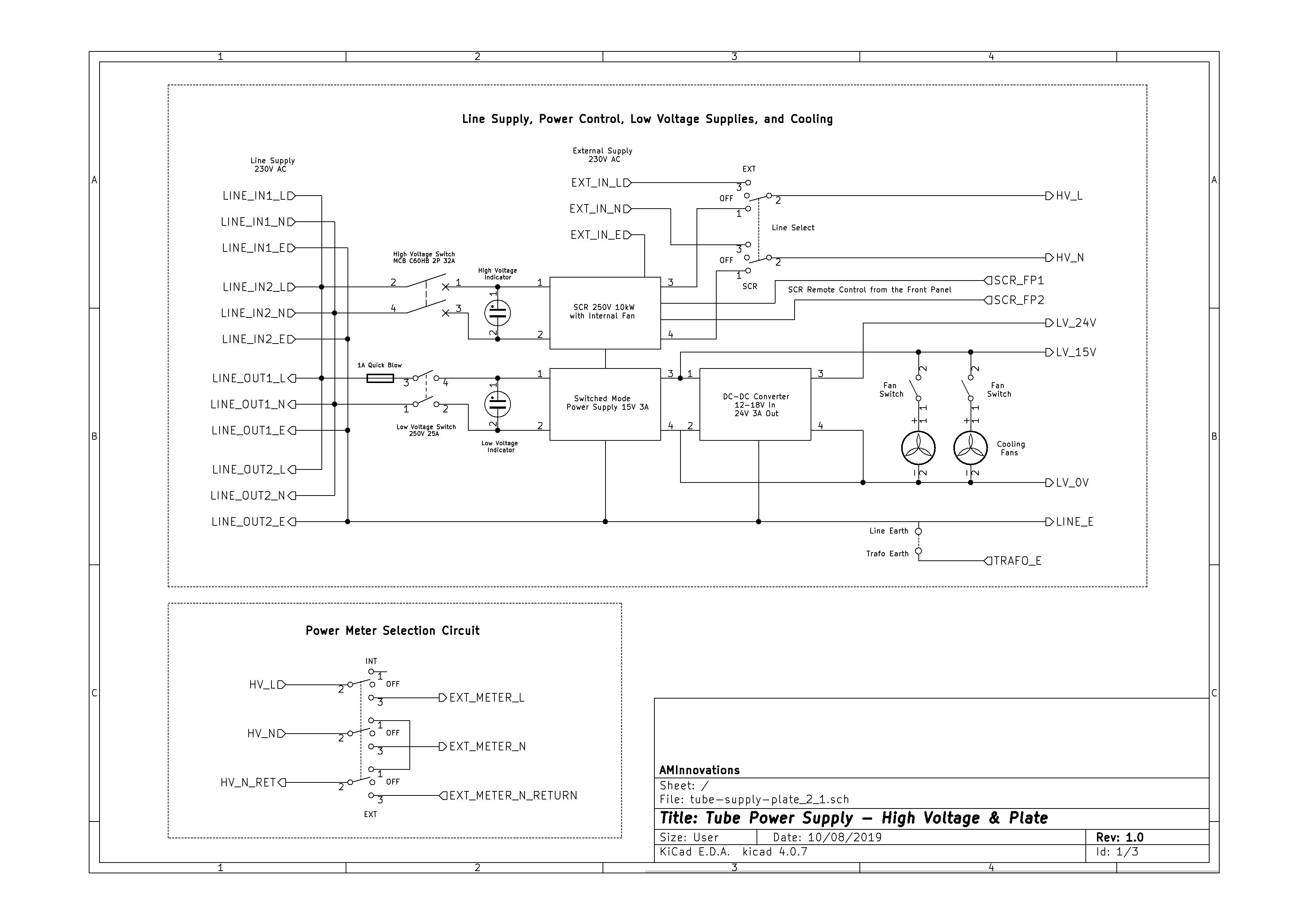
Fig 3.2 shows the circuit diagram for the Line Supply, Power Control, Low Voltage Supplies, and Cooling. The line supply from the rear input panel provides both line supply outputs for chained connection of other modules, devices, and instruments, and internally splits into two feeds, one for the HV supply, and one of the low voltage (LV) supply. The LV supply is fused and switched with a LV indicator to show active operation. The LV line supply feeds a 15V 3A switched mode power supply which powers all the internal LV components, and also has external outputs to power other LV devices and modules in the experimental setup. Internally the 15V is stepped up to 24V by a DC-DC converter. The 24V is suitable to switch the W1W or B1B vacuum relays which operate quickly and reliably at the higher voltage. The internal cooling fans are both switched and are powered from the 15V LV supply. The fans are especially necessary during prolonged high power usage, and are positioned directly behind the HV transformers.
The HV supply is protected by a dual-pole 32A MCB, (upgradeable to 40A MCB in extreme conditions), and with a neon indicator to show active operation. The HV line supply is fed directly to a 250V 10kW SCR which is arranged for both internal and remote control via the front panel. The SCR provides progressive power control for HV transformers which is often most necessary for microwave oven transformers that have had their magnetic restriction shunts removed. The SCR voltage profile is also highly non-linear which in some experiments like Tesla’s Radiant Energy and Matter, and Displacement and Transference of Electric Power series, is most useful to reveal, accentuate, and maximise certain types of phenomena including displacement and radiant energy, and dielectric induction field charging and storage. The SCR output is fed to a line supply selection which switches either the SCR output or external line supply input to the power control front panel. The line supply selection was included to allow for quick switching to a variac for progressive linear control of a sinusoidal line supply which is most useful during experiments with phenomena that vary with supply voltage profile.
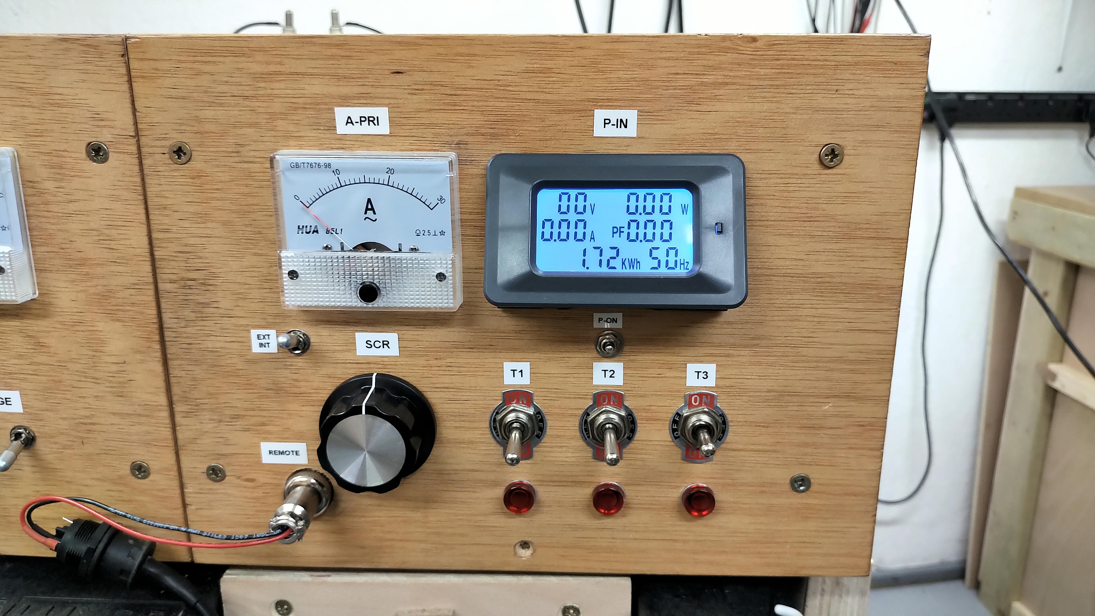
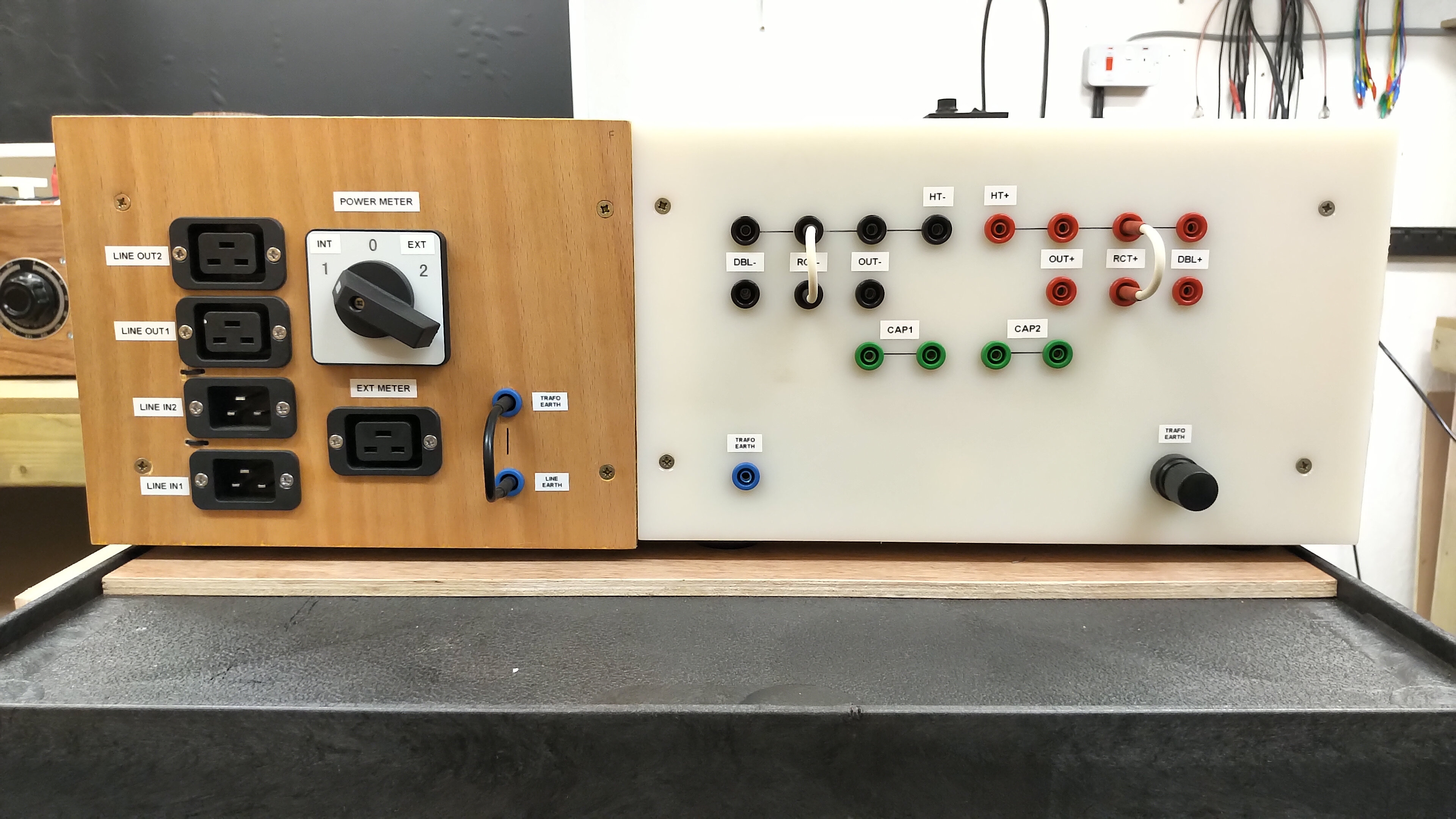
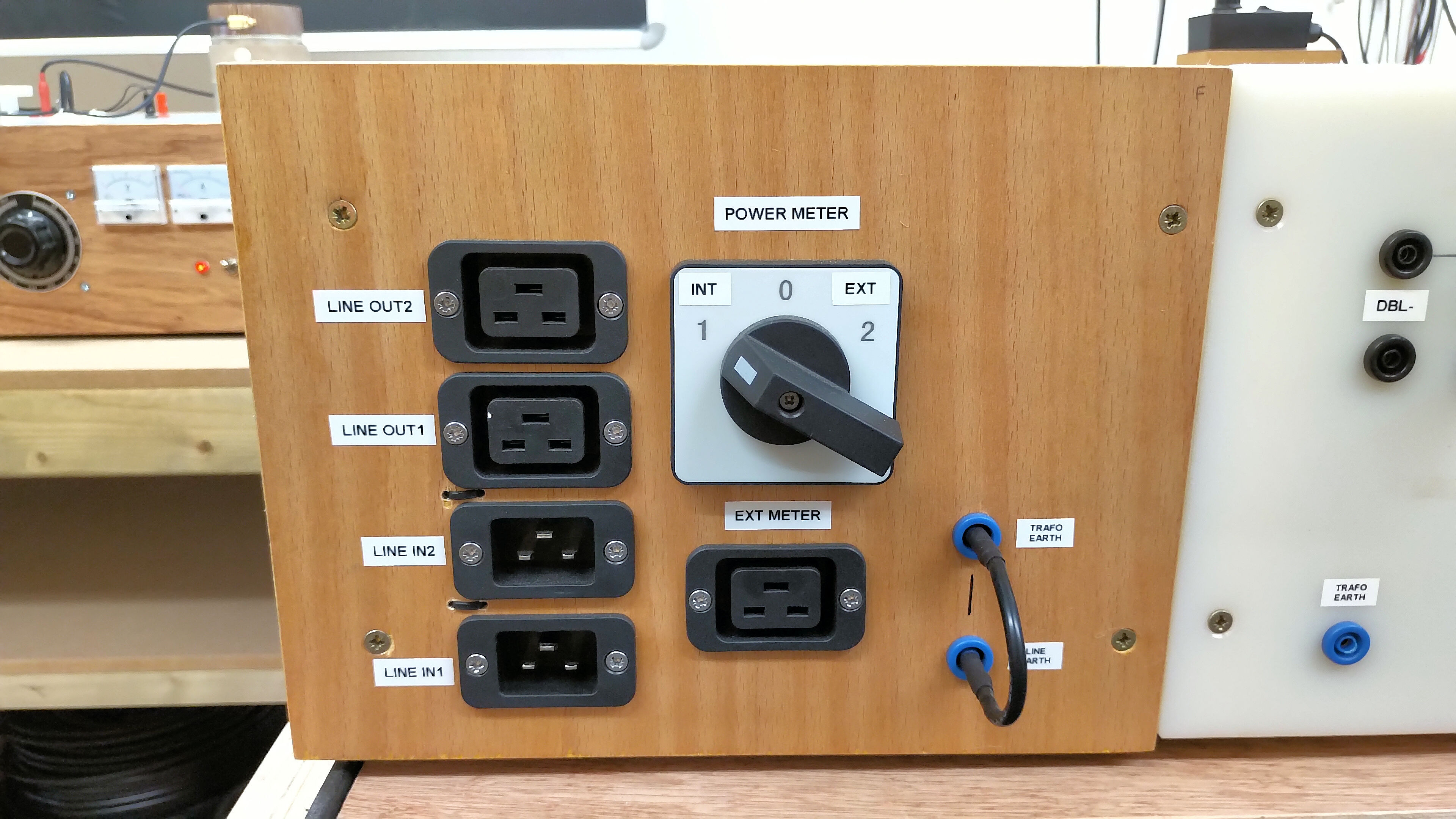
Fig 3.1 shows the circuit diagram for the Power Input Control Front Panel which consists of the following:
1. The three off and phase control transformer switches. Line supply from the selection switch on the main power panel is fed to the switches each with three positions, off and up and down, where the up and down positions switch the line supply to the respective transformer, and also swap the live and neutral from up to down to control phase control of the transformer primary. Each switch is accompanied by a neon indicator that both shows if the transformer is currently active, and the intensity that the transformer is being driven.
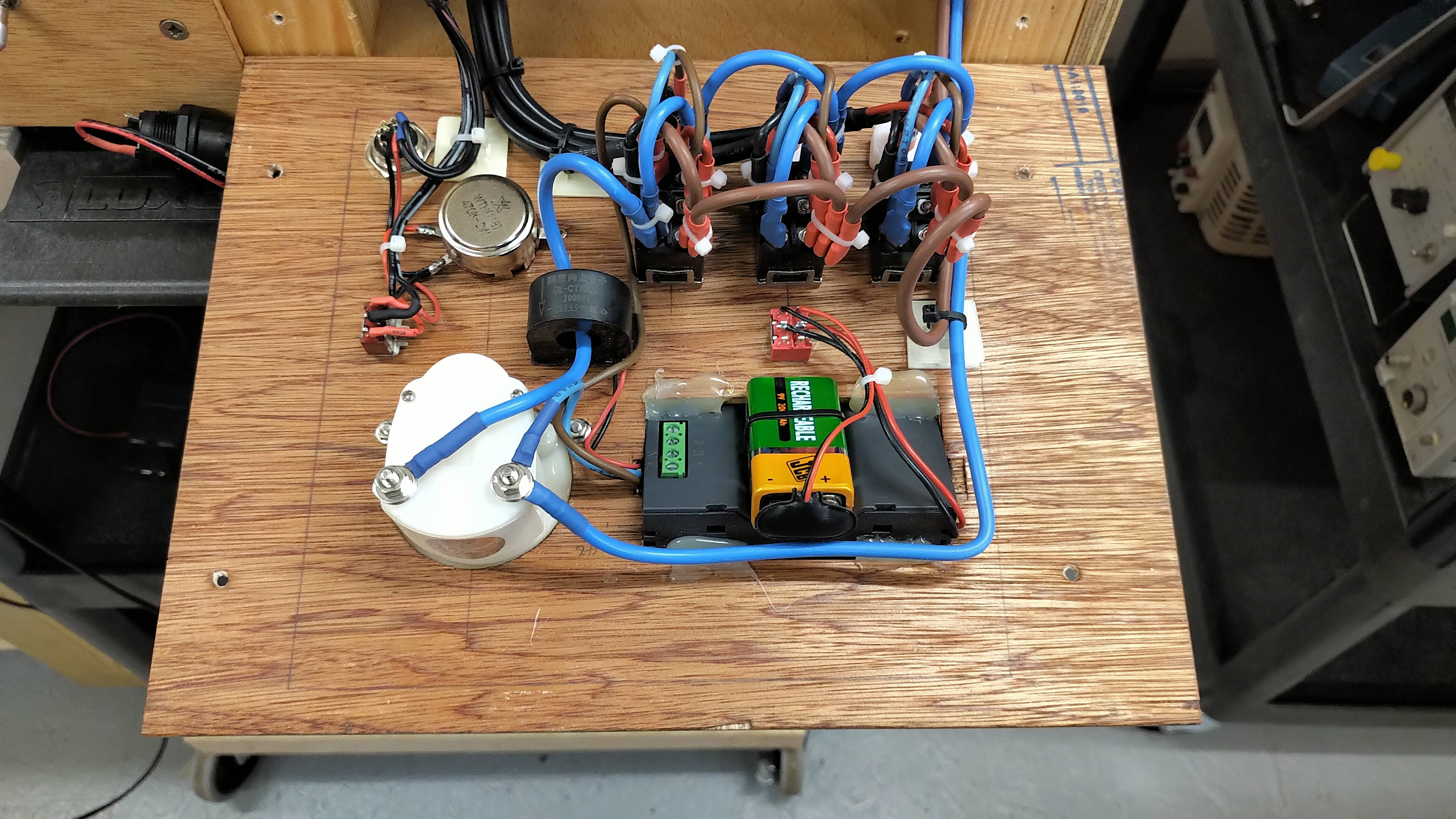
2. The digital power monitor is 9V battery driven in order to have independent operation from the line supply, and continues to be active even if the line supply is removed, this is important for safety in the event of a fault where the line supply is still connected to the rear panel, but has become disconnected internally due to say an SCR open circuit fault, and line supply to the transformers can still be monitored. The digital power monitor takes input directly from the line supply fed to the front panel for voltage, and for current via a current transformer in the neutral line supply return, and mounted to the inside of the power control panel. The meter has an on-off switch P-On, and is also angled upwards in the panel for easy reading. The meter provides a useful real-time summary of all operating measurements on the line supply side, including apparent voltage and current, real power indication and consumption, and total power factor.
3. The neutral line supply return also includes a 30A AC meter which is particularly good for quick monitoring of the total transformer primary current. This is useful in high current drive scenarios when changes in tuning can easily place the power supply in a very different operating condition, where very large currents are suddenly drawn from the line supply e.g. whilst tuning through the transition between the lower and upper parallel resonant modes of a Tesla coil whilst driving at moderate to high-powers > 1kW.
4. A locking switch to change from the internal SCR control potentiometer to the external remote control potentiometer. The switch is locking in order to avoid accidental switching which could yield dangerous and unexpected results if the SCR suddenly was switched to a higher power condition. The selected potentiometer connects directly back to the SCR on the main power panel and controls progressively the active portion of the line supply cycle that is fed to the transformers.
5. The remote control socket is a 10-pin connector which currently has 2 lines for the SCR remote potentiometer, and 2 lines to switch the HV discharge module on and off. The other 6 lines are not used and available for future expansion and functionality.
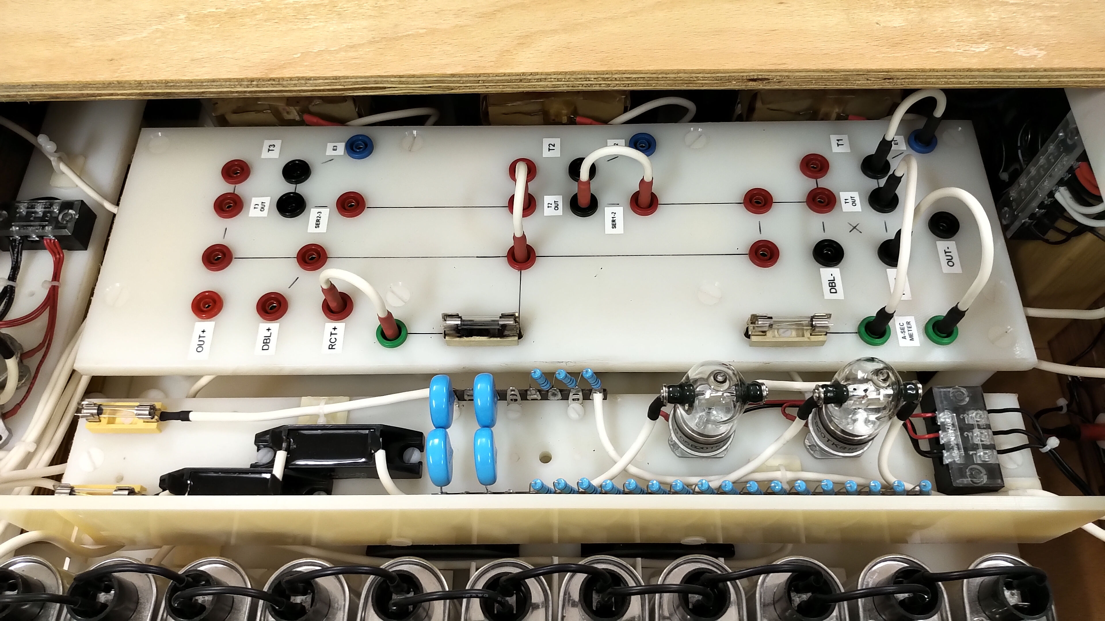
Transformers and Patch Board
Fig 3.1 shows the circuit diagram for the Transformers and Patch Board. The microwave oven transformers (MOT) are a heavy-duty industrial type rated to 1.8kVA with the magnetic shunts removed. A traditional MOT is a cheap high voltage transformer manufactured with the minimum weight of copper and hence cost, and designed to match the very specific impedance of a magnetron when correctly matched using the level shift capacitor. The cheap construction of the transformer usually involves welding the laminated metal core together on both sides, which whilst simple to make, results in shorting out much of the laminated core reducing it electrically to a large block of magnetic material that will easily saturate when sufficient power is applied to the primary coil. In this basic form the MOT does not easily lend itself to a progressive linear power supply at high voltage, like other types of high voltage transformers. The MOT however does benefit from being very robust and also able to supply high currents up to easily 1A at around 2kV AC.
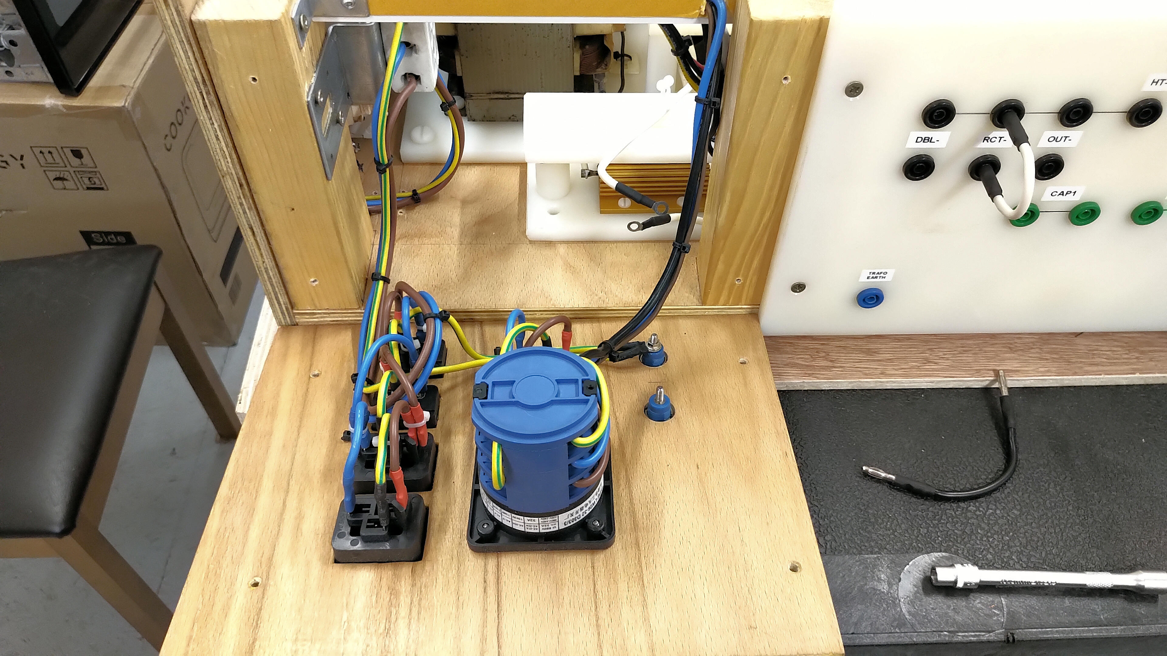
The magnetic shunts are so arranged during manufacture of the MOT to reduce the free magnetic coupling between the primary and secondary coils, and hence limit the power transfer from primary to secondary, driving the magnetron impedance efficiently, without core saturation and hence excessive heat generation, and without pulling excessive current from the line supply. When reused as a high voltage transformer in this type of plate supply the magnetic shunts restrict significantly the maximum power output performance of the transformer, and need to be removed carefully (to avoid damaging the windings), with a drift and heavy mallet. I made up a wooden jig screwed to the bench to hold the transformers securely whilst driving out the magnetic shunts. The un-shunted MOT now benefits from no restrictive magnetic coupling, but does now need to be current limited to prevent excessive core-saturation at the top-end of the line supply input, and with higher impedance loads at the output of the generator e.g. a vacuum tube generator.
Current limiting can be achieved a variety of ways, including chokes in the primary and/or secondary coil circuits, but in this plate supply I use an SCR power controller which provides progressive power output by varying the active line supply cycle. The SCR introduces large non-linear distortion in the line supply to the transformers which is both a hindrance in some experiments and requires to be smoothed with large HV capacitors, or a benefit in generators designed to emphasis certain non-linear phenomena e.g. displacement and radiant energy experiments. Oscilloscope waveforms of the SCR drive of a MOT, and for more details on using a MOT as a high voltage transformer see High Voltage Supply. Overall the MOT when correctly used and setup is a very robust and high power transformer, which with cooling can run at very high output powers for sustainably long time periods. Combinations of MOTs in parallel and series can generate a wide range of high current and high voltage outputs, which is the principle I have used in this high voltage plate supply.
The three MOTs are switched independently from off to specific line supply phase (live and neutral connection to the primary) by the three toggle switches T1 to T3 on the power control front panel. The MOTs themselves are physically arranged on a nylon plastic sheet so that the MOTs cores are not electrically connected. The core of a MOT usually forms one terminal of the high voltage output, the inner end of the secondary being connected directly to the core. In this way the transformers can be isolated from each other and then connected via the patch board into different combinations of single, parallel, or series connected. Configurations of the transformers using the patch board is detailed in Figures 4, and further discussed below in that section. The patch board provides both connection of the transformers together in different configurations, and also connection of the the configured transformer set to the various internal modules of the power supply as follows:
1. The OUT+ and OUT- terminals take the raw transformer output directly to the HT output board, and allow for direct drive at the output from the transformers.
2. The RCT+ and RCT- terminals connect the transformers to the HV bridge rectifier inputs, and its outputs are connected to the HT output board.
3. The DBL+ and DBL- terminals connect the transformers to the HV level shifter inputs, and its outputs are connected to the HT output board.
There are two protection fuses at the high-side and low-side of the transformer outputs and prior to connecting to any of the internal modules or HT output board. The high-side fuse is particularly good to prevent excessive current draw through the bridge rectifier and level shifter diodes, whereas the low-side fuse is particularly good to prevent spike surges from the transformers and through the diodes, when for example a vacuum tube oscillator stops oscillating at high output power, and then suddenly restarts oscillating. Both high-side and low-side fuses are necessary to protect the supply from a range of different operating fault conditions, which is very important in extreme research and prototype operating conditions. I lost one set of bridge rectifier diodes (12 x HV diodes) before I used the high and low side protection fuses. A 2A FSD AC analogue meter is connected in series with the low-side fuse, which gives an average approximation of the secondary current being drawn from the complete transformer setup. The inter-connection of the patch board, outputs, and meter is via 4mm plugs with 20kV 16AWG wire.
High Voltage Bridge Rectifier
Fig 3.1 shows the circuit diagram for the HV Bridge Rectifier, which is mounted below the patch board on the transformer module, and shown in detail in Fig 2.22. The rectifier is nominally 40kV @ 6A and is constructed from 12 x HVP2A-20 20kV 2A diodes. The diodes are mounted directly down to the nylon transformer board and again connected to the patch board and HT output board using 20kV 16AWG wire. Whilst quite well rated for the overall performance of the plate supply, semiconductor diodes are sensitive devices and easily blown short-circuit by over-current conditions, and blown open-circuit by HV spikes, transients, and non-linear power reflections from the experiments.
To protect these diodes, we use both the high-side and low-side fuses on the patch board, and also most importantly a blocking/tank capacitor at the HT output board. This capacitor significantly helps to prevent reflected transients and non-linear voltage spikes from the experiment and generator from passing back into the power supply and causing problems for the sensitive semiconductors. Typically for many experiments using a vacuum tube generator, and when a smoothed DC plate supply is not required, I use a 25kV 25nF pulse capacitor as the block capacitor at the HT output board. For DC smoothed plate supply I tend to use two 4kV 60uF capacitors in series to create a 8kV 30uF tank reservoir. A large tank like this needs very careful connection and discharging, which is one of the primary reasons a discharge unit is included in the power supply.
Overall when used with the blocking capacitor the HV bridge rectifier is robust and reliable, and can provide sustained high output power with only moderate heating of the diodes. These rectifier diodes are also in direct line of the forced cooling between the MOTs which makes for a high power high voltage rectified and smoothed DC plate supply or HV source. I have only lost one set of diodes before I had the high and low-side protection fuses installed, when operating at almost full power input and the vacuum tubes stopped oscillating during a tuning experiment. When it started oscillating again the current surge from the transformers at an almost full input power of 5kVA blew all 12 diodes short circuit. The high and low-side fuses now provide adequate protection against this fault condition, and I usually run with protection fuse ratings between 1-3A dependent on the transformer configuration, required output power, and type of generator e.g. vacuum tube, spark gap, impulse etc.
High Voltage Level Shifter (Doubler) Board
Fig 3.3 shows the circuit diagram for the HV Level Shifter or Doubler. The large microwave oven capacitor bank and 6 HV diodes that constitute the level shifter are mounted on its own nylon board, and are shown in detail in Fig 2.15. The principle of the level shifter is that in one half cycle of the secondary output the capacitor bank is charged up to the peak potential of the half-cycle e.g. 2.1kVRMS for a single transformer, and in the second half cycle a diode is used to raise (or lower dependent on the direction of the diode) the potential on the output of the capacitor bank by the maximum potential of the second half-cycle e.g. a further 2.1kVRMS for a single transformer. The overall result for a sinusoidal primary coil line supply input is an secondary output sinusoidal that is level shifted either up or down by the maximum potential of one half cycle of the waveform.
With a positive orientated diode direction this will produce a sinusoidal from 0V to 4.2kVRMS or ~6kV peak voltage when unloaded. In other words the secondary coil output waveform is level shifted either positive or negative dependent on the diode orientation, and hence why this circuit setup is properly known as a level shifter. This circuit is often referred to as a voltage doubler, but diverges slightly from a true doubler that uses multiple diodes and produces a rectified and doubled, or tripled etc. output dependent on the number of capacitor diode stages in the voltage multiplier. In this power supply I use the diode in the positive orientation to produce a positive level shifted output which can be selected using DBL+ and DBL- on the transformer and HT output boards. It is not without a sense of irony that I refer to the terminals as “DBL” or short for doubler!
The capacitor bank is an MMC type arrangement that consists of many microwave oven capacitors combined together to produce a higher capacity capacitor, and at a higher voltage. In this case I am using a bank of 3 x 1.05uF 2.1kVRMS capacitors in series to give a 0.35uF 6.3kVRMS single bank. With 11 of these banks combined in parallel the final capacitor bank is ~ 3.8uF @ 6.3kVRMS. When used in a level shifter configuration as shown in the circuit diagram this capacitor bank with 3 series input transformers can give a measured total level shifted output potential of up to 13kV @ 300mA, 15kV @ 150mA or almost 18kV peak open circuit potential. The diodes are again the same as those used in HV bridge rectifier and are arranged in 2 series banks of 3 in parallel to provide a 40kV 6A level shift diode.
High Voltage Monitor Board and Panel
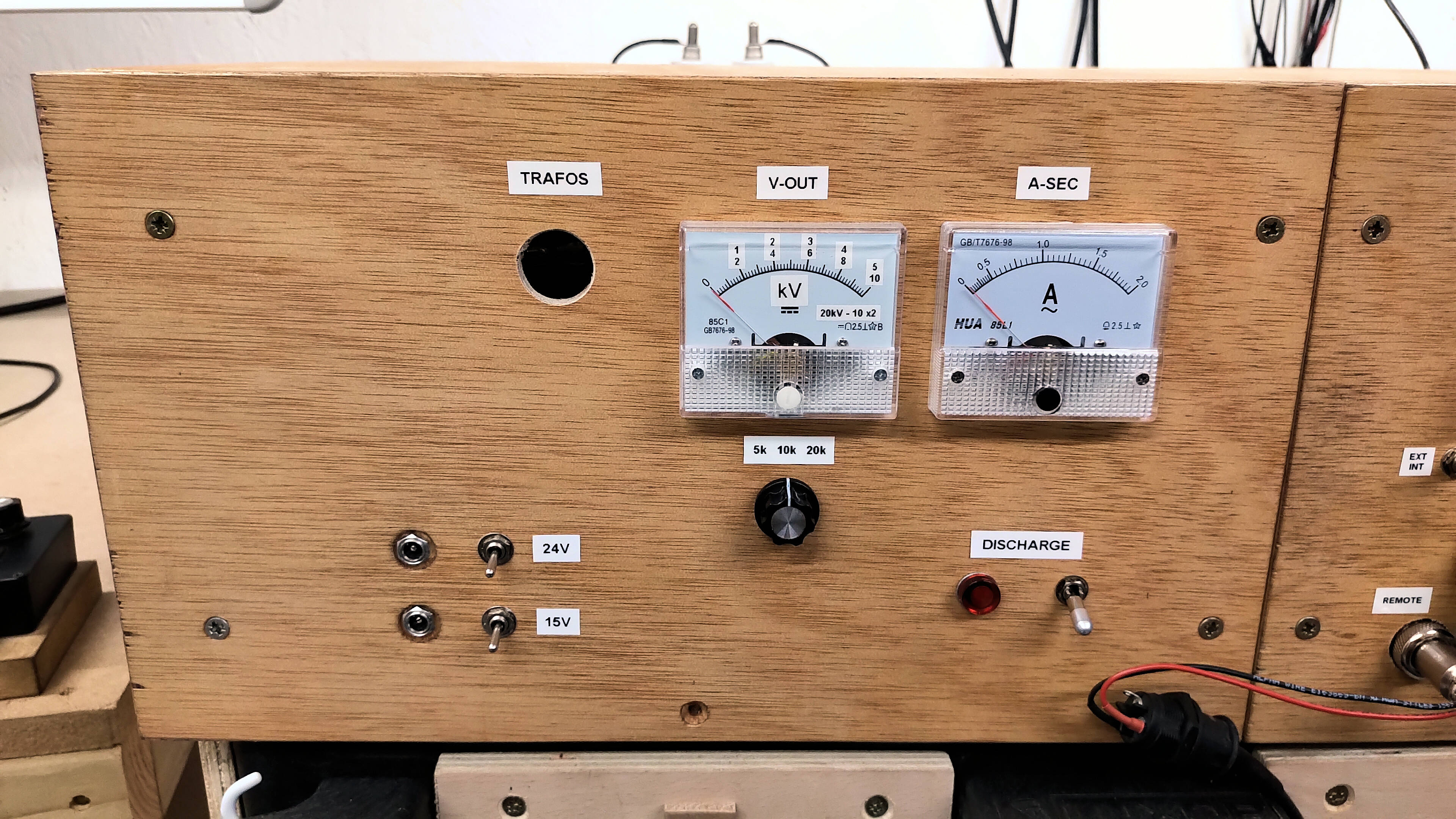
Fig 3.1 shows the circuit diagram for the HV Output Monitor Board (HVOM), which is designed to safely provide a measure of the HT Output on the Power Output Monitor Front Panel, also shown in the circuit diagram. The HVOM circuit uses a HV half-wave rectifier using 2 x HVP2A-20 in series making a 40kV 2A rectifier diode. The rectified waveform is smoothed by an HV capacitor bank of 2 series and 2 parallel capacitors to form a 10nF 40kV smoothing capacitor bank. The rectifier and smoothing capacitor together turn the output waveform into a peak DC level which will be displayed on the front panel V-OUT meter as shown in Fig 2.6. The high voltage peak DC level is converted to a low current by a long series resistor chain, where each resistor is 1MΩ 2W. 20 series resistors together form the highest 20kV range and reduce the current from the rectifier to 1mA for 20kV. This dramatic reduction in current reduces the ripple on the peak DC to a very low level, and also safely converts the HT to a low current that can be passed to a meter on the front panel.
The meter on the front panel is a 1mA FSD DC analogue meter with its range updated to show kV rather than mA. So on the highest range 20kV at the HT Output Board is converted to 1mA and moves the meter needle to full-scale deflection. The 5kV and 10kV ranges are arranged by taking a tap point off of the resistor chain after 5 and 10 resistors respectively. The tap connections are arranged by a pair of HV vacuum relays which are switched by the 24V low voltage rotary position switch on the front panel. Although rated to only 3kV 10A each in this setup the relays can withstand much higher potential difference across their contacts as the current in the series resistor chain reduces the discharge current to a very low level, and hence breakdown across the contacts is suppressed.
In this way the HVOM can safely and effectively measure peak voltages up to 20kV DC in 3 ranges, 5kV, 10kV, 20kV which can be selected and displayed at the front-panel, without any HV present at the front panel controls. For additional protection from an unknown fault condition the rotary selection switch and knob on the front panel is entirely of plastic case and shaft design. It is worth noting that both the 5kV and 10kV range require one of the vacuum relays to be energised, and hence a 24V supply must be present for these two ranges. In the event of a power outage to the unit both relays will be off, and the meter will fall-back to the 20kV range by default. This must be considered carefully when using large tank capacitors which are highly charged by the supply, and they are being monitored on the 5kV or 10kV range, and then a sudden fault condition where to remove the line supply input, the meter would fallback to the 20kV range appearing to show considerably less voltage on the HV capacitor bank.
In the design of a high power, high voltage power supply it is important at the early design phase to allow for unknown and unusual fault conditions and how to protect both the operator and components from exposure to unsafe conditions. High voltage has an uncanny knack of finding the most surprising discharge and breakdown channels, and hence distance between high voltage components, breakdown resistance of insulators, and mounting materials must all be carefully considered and arranged. In this power supply all the HV components are mounted on nylon boards and supports fully isolating them from the varnished wooden casing, and from other metal and conductive brackets, mounts, and modules used in the supply construction. HV is passed around the supply on the inside using 20kV silicone coated 16AWG multi-stranded hookup wire, and the layout of the modules are so arranged to minimise the wiring length between HV modules and the HT Output board.
The inputs to the HVOM are further protected by two 1A line fuses on the low and high-side inputs. These are arranged to prevent fault conditions from destroying the rectifier, capacitors, and other monitor components in the event of an unusual fault condition in the HVOM board or monitor panel components. This was added to the design after the early prototype was being run in 10kV maximum power output test, and with a lower rated smoothing capacitor, which failed short-circuit and pulled an enormous discharge current through the rectifiers, super-heating them to a point where they exploded sending Bakelite shrapnel all around the supply enclosure and into the lab, and physically puncturing two of the level shifter microwave oven capacitors in close vicinity!
The smoothing capacitors where subsequently uprated, and fuses added to prevent reoccurrence of this kind of fault. It should however be noted that if one or both of these input fuses blow then the V-OUT monitor meter will read 0V even when there may be high tension present on the HT Output Board. It should also be obvious to the reader why careful and safe testing using the remote control is a necessity when first commissioning, and whenever operating this king of of high tension supply.
High Voltage Discharge Board
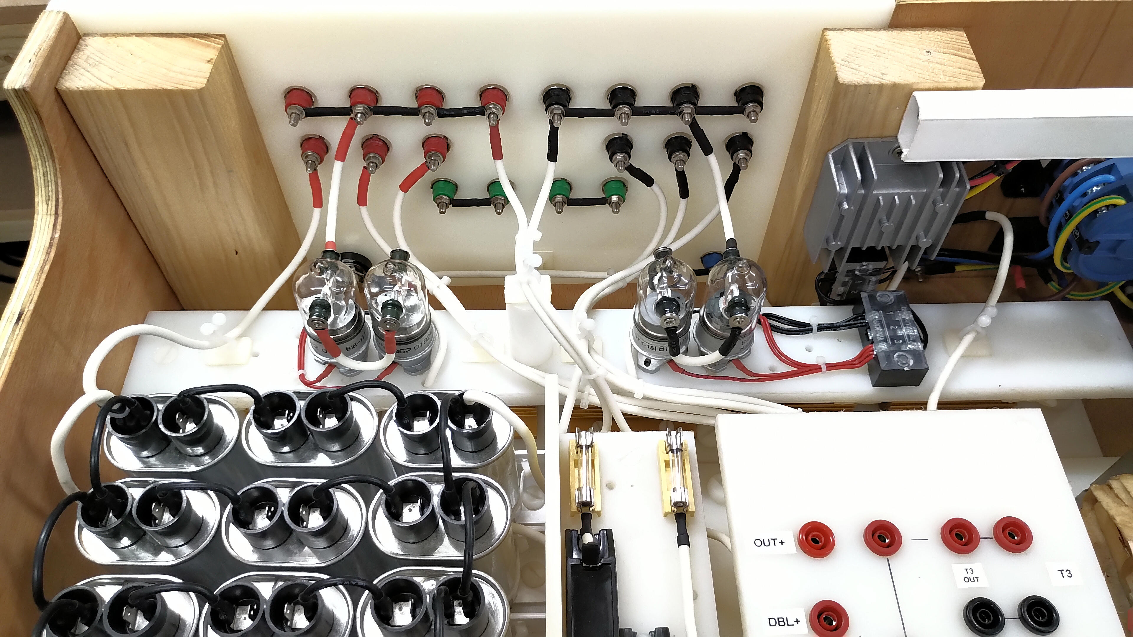
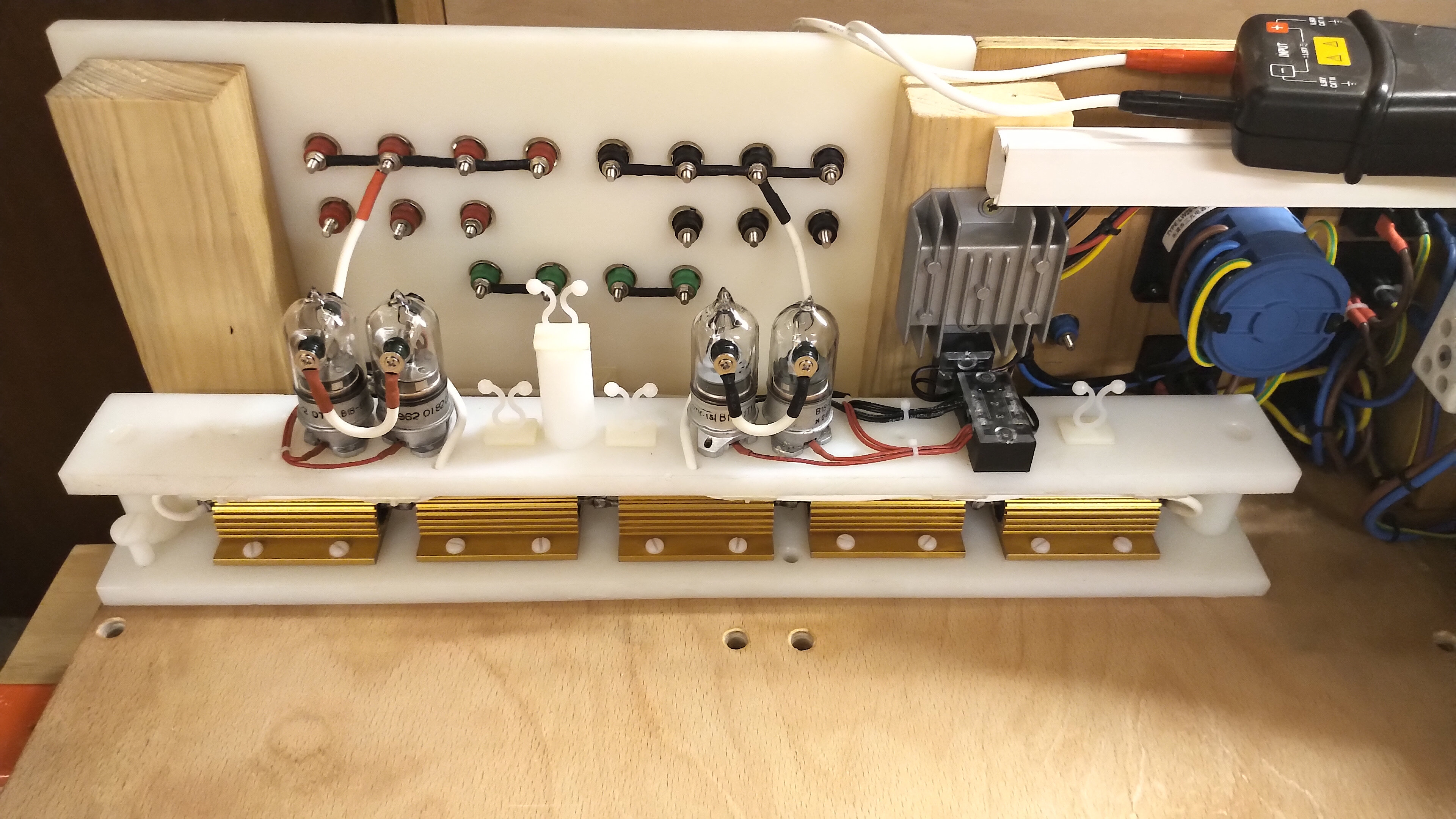
Fig 3.3 shows the circuit diagram for the HV Discharge Unit, and its implementation and construction are shown in detail in Fig 2.19. The discharge unit performs a simple and yet critical safety task, which is to discharge any high voltage that is present at the HT Output panel when the transformers are turned off. This high voltage may arise from the experiment and generator or from tank/blocking capacitors attached to the output. In a research and development environment it is usual to adapt the apparatus, experiment, and method may times during operation, and this requires being able to safely work on the equipment between operation and after fault conditions, issues, or unexpected events. This requires rapid access to a safely discharged experiment system which obviously includes the power supply. The discharge unit is an effective and reliable method to discharge very large energy stored on high capacity components in the circuit.
An example of this is as follows. The plate supply was used with the Tesla coil unit featured in the Wheelwork of Nature series, which includes a vacuum tube generator based on a single GU5B class-C Armstrong oscillator. One of the variations of this experiment used an 8kV 30uF tank capacitor at the output of the HT Output board. During extreme band-edge tuning the vacuum tube stopped oscillating, and would not restart during the experiment. With the line supply turned off at the plate supply, this left the tank capacitors charged to over 6.5kV! A 30uF tank capacitor charged to 6.5kV is storing in the region of 635 Joules of energy, which at that high potential is massive.
Discharging a high voltage capacitor with this potential and energy stored on it safely is a serious task, and cannot for example be undertaken by the old screwdriver short across the terminals. Bleeder resistors mounted permanently across the capacitor terminals are of course a necessity with a HV capacitor bank, but this takes a very long time to discharge this level of stored energy. This much potential and energy is instantly lethal under any condition, and the operator does not want to be anywhere close to the experiment or power supply whilst in this charged state. This is where the HV Discharge Board is of invaluable assistance, and when operated using the remote control, a safe and quick method to discharge this high stored energy without damaging any of the components, the HV capacitors, or the operator!
The HV Discharge board is based very simply on a high power resistor chain, in this case 5 series connected 4.7kΩ 100W 2.5kV wire-wound power resistors combine to give a 23.5kΩ 500W 12.5kV power resistor. This power resistor is capable of safely discharging output potentials up to the loaded condition of 15kV @ 150mA, from 3 series connected transformers combined with the level shifter. Although the power resistor chain is nominally rated to 12.5kV the restriction of current and short discharge time constant means that 15kV is rapidly reduced below 12.5kV without adverse effects on the discharge module. In daily use the supply very rarely operates at this 15kV level and usually only with spark gaps or thyratron generators, the normal routine being from 4-10kV for most of my vacuum tube generators. The construction of the unit is compact with the HV relays closest to the HT Output board and with the power resistors also closely connected on the lower level. Overall the unit is positioned and connected very close to the source of HT to be discharged.
The power resistor chain is isolated from the output circuit using 4 series high voltage vacuum relays, 2 on the high-side and 2 on the low-side. The combined nominal isolation from 4 x 3kV 10A relays is 12kV @ 10A. These relays also operate safely at 15kV and particularly because of the current restriction due to the resistor chain. Once again in mostly normal operating from 4-10kV the entire HV Discharge Unit is operating comfortably within its maximum nominal ratings. The unit is switched both from the front panel and from the remote control and takes only seconds to discharge the example given above of a 30uF capacitor charged to 6.5kV. The 500W load consumes the 635 Joules of energy in about 3 seconds with barely detectable heating of the resistors. I usually then leave the discharge unit on whilst I am attending to the power supply or experiment before turning off before next operation. The on condition of the discharge unit is indicated by a bright red LED on the front panel to warn against transformer operation with the discharge unit turned on.
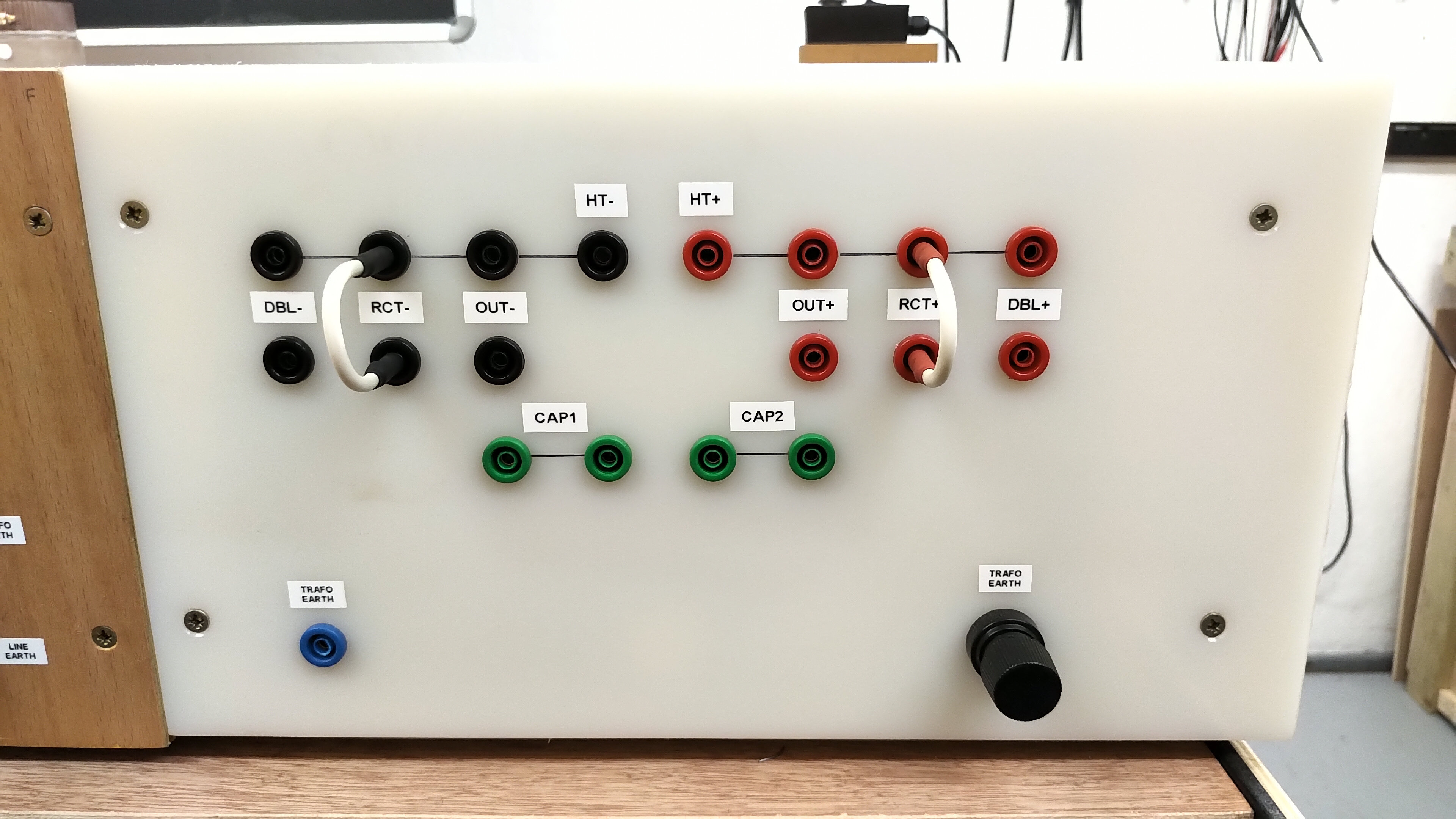
High Tension Output Panel
Fig 2.12 shows the HT Output panel in detail. The HT+ and HT- are each connected rails which form the final high voltage or high tension outputs. The various internal modules, OUT, RCT, and DBL can be connected to the output rails using HV jumpers. The left over terminals on each rail is then very convenient for the connection of the experiment, HV capacitors, measurement probes etc. The CAP1 and CAP2 connections are provided to conveniently connect series chains of HV capacitors providing safe and intermediate connection points in the chain. The output panel also has 4mm socket and heavy-duty terminal for the transformer earth to allow experiments to be referenced directly to the floated or connected transformer earth. This panel is the only one made in nylon to prevent any leakage or discharge between module terminals and outputs when used up to the maximum 18kV open circuit condition from 3 series transformers connected to the level shifter.
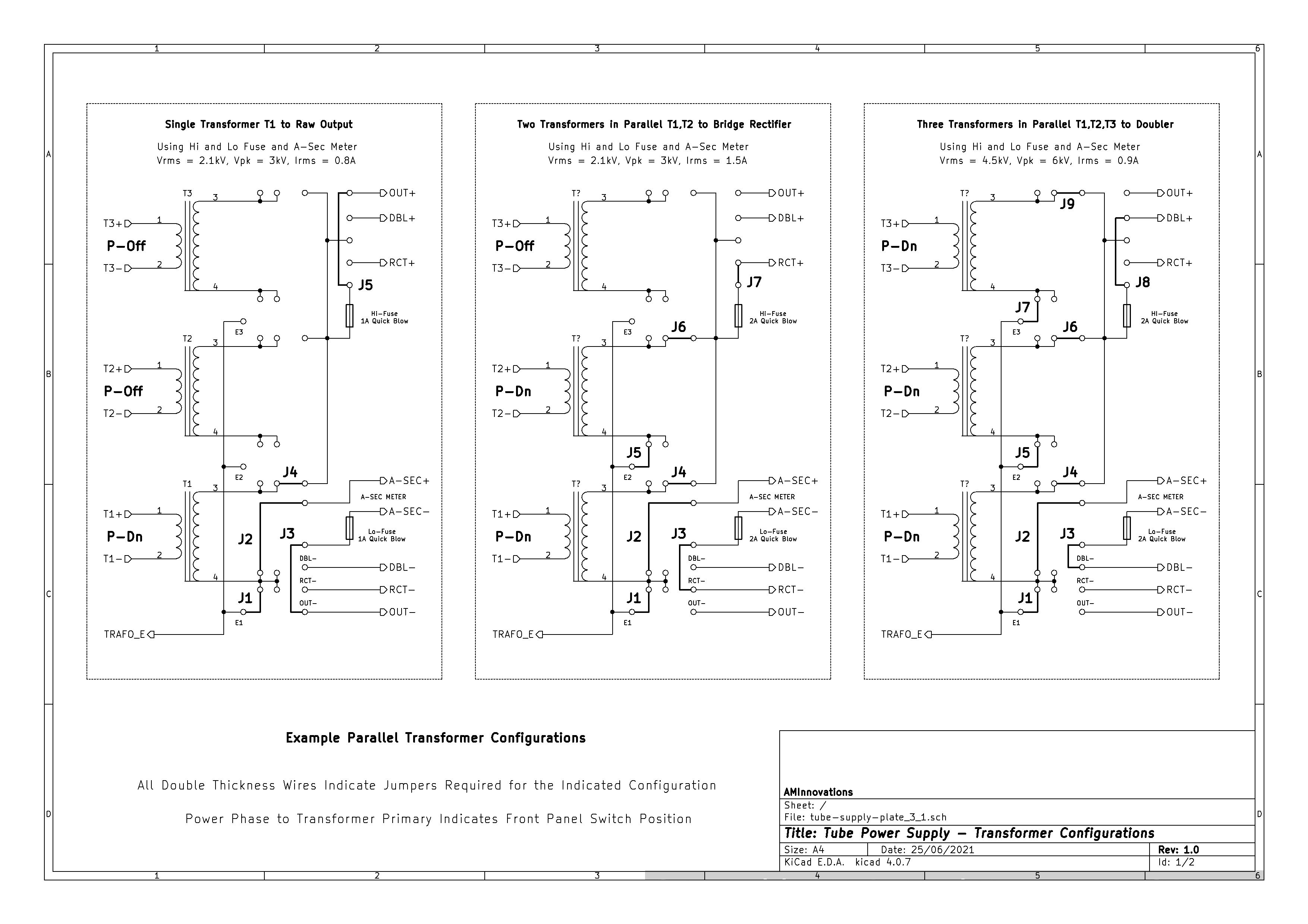
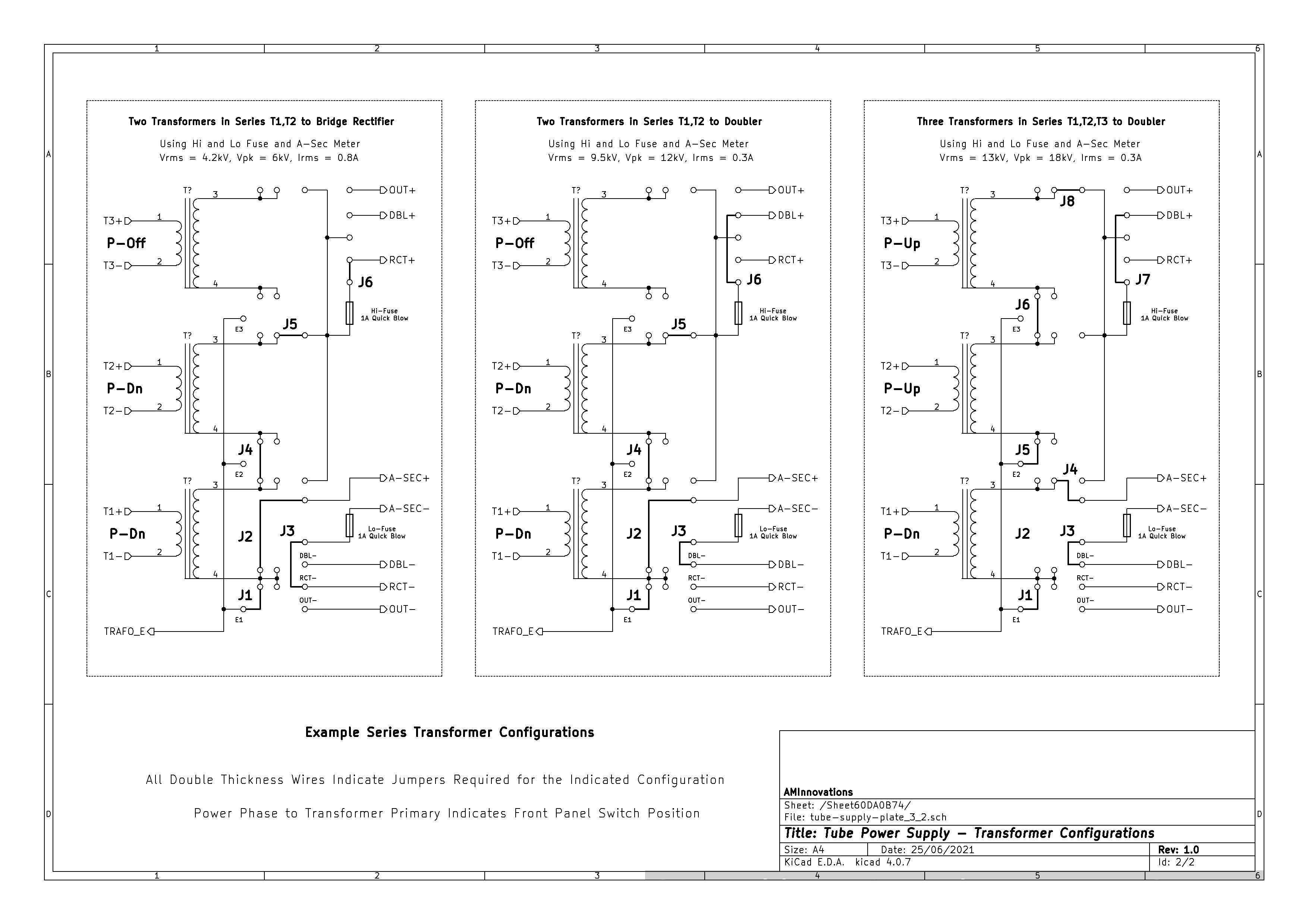
Figures 4 below show the example transformer connection diagrams to setup the supply into different configurations. I have selected a range of the most useful parallel and series setups, and which also configures the supply over its full range of voltage, current, and power output. The high-resolution versions can be viewed by clicking on the following links Fig 4.1, and Fig 4.2.


General Setup
In the final few sections of this post we look in more detail to the internal configuration of the plate supply using the transformer patch board, and the HT output rear panel. Any configuration of this supply must consider the requirements of the generator and experiment in terms of the required maximum voltage, current , and total power both real and reactive that will be drawn from the supply under different operating conditions e.g. varying tuning, matching, and output loading. With this established then the most simple, reliable, and optimal supply configuration can be arranged by setting up correctly the internal jumpers of the supply in order to meet the output requirements.
For example in the case of the GU-5B Armstrong oscillator coil unit used in the Wheelwork of Nature series, the nominal maximum plate potential is ~5kV. The CW power rated output when suitably cooled and driven around 1-5Mc for this tube is ~2.5kW, so at 5kV and 2.5kW of power the anode current could reach as high 0.5A. Considering current surges during extreme tuning experiments the anode current could reach considerably higher levels for very short time periods. The grid bias to keep the GU-5B oscillating under these conditions will need to be in the order of ~ 100mA – 500mA and can be adjusted using the grid bias rheostat for optimum drive matching to the experiment. Taking all this into consideration 2 series transformers will reliably supply ~ 4.2kV @ 0.8A, and up to 6kV open circuit, and 2 parallel transformers combined with the level shifter would provide ~ 4.5kV @ 0.6A, and again up to 6kV open circuit. For simplicity here I would use the 2 series transformers which also gives a better current rating, and less dissipated power with fewer HV components (less to go wrong) in the overall setup.
Now empirically the GU-5B can withstand substantially higher plate voltages when the generator is driven in low duty cycle pulsed mode, or using a staccato controller in the vacuum tube cathode connection. The advantage of this extreme operating condition is that the considerably increased anode potential will also considerably increase the peak-to-peak oscillation across the primary coil, which in turn will considerably increase the voltage magnification along the secondary coil, ultimately leading to much longer discharge streamers from the top-end of the Tesla coil secondary.
Under these operating conditions the plate supply could be as high as 9kV, and this would be best supplied by 2 series transformers with the level shifter which can supply up to 9.5kV @ 0.3A. In this extreme operating condition care needs to be taken not to allow the GU-5B to stop oscillating at full input voltage and power from the plate supply, as the tube anode would then be exposed to an open circuit voltage of almost 12kV which is too high for the GU-5B under any circumstances and could easily lead to anode-grid breakdown and destruction of the vacuum tube. Extreme operating conditions such as this have to be handled extremely carefully and with experience, but are discussed here to illustrate the setup of the plate supply necessary to operate in this region.
The other important consideration for the generator and experiment is the voltage envelope or driving waveform that is provided by the plate supply. For example the characteristics of a Tesla coil can vary enormously when the generator is driven by a sinusoidal, pulsed, chopped, or rectified and smoothed high voltage waveform. A setup consideration for the plate supply is whether to drive directly with the raw transformer output, use a rectified output with or without a tank/blocking/smoothing capacitor, or an output that is a continuous sinusoidal or chopped by an SCR. My own preference for these selections are as follows, but do very much depend on the type of generator being driven e.g. spark gap or vacuum tube, and the type of Tesla coil and phenomena that the experiment is working with e.g. Tesla’s Radiant Energy and Matter, Transference of Electric Power – Part 1, Single Wire Currents etc.
1. For experiments and generators in CW mode e.g. The Wheelwork of Nature – Fractal “Fern” Discharges, and High-Efficiency Transference of Electric Power, I use the bridge rectifier module with a tank/blocking capacitor as this allows for maximum power output efficiency from utilising both half-cycles of the transformer output, and also creates a positive forward pressure or positive voltage envelope. With a large tank/smoothing capacitor this makes for a very steady DC level anode supply which will result in high currents and hence strong, hot discharge phenomena, from powerful oscillations in the primary circuit. The blocking capacitor protects the semiconductor rectifiers from spikes and reflected power surges and transients.
2. For experiments and generators using spark gaps, or vacuum tubes in pulsed mode using a staccato interrupter, or other triggered grid devices e.g. Transference of Electric Power – Part 2, I prefer to use the raw output of the transformers in either parallel or series connection. The burst nature of the output especially with the SCR power control leads to enhancement of the non-linear and impulse like phenomena, and the setup of the pulsed triggering and staccato phasing is easier when matched to a positive or negative half-cycle envelope. This configuration is very robust for extreme operating, tuning and matching, as only the transformers are exposed to the raw output. MOTs are extremely robust provided they are not allowed to excessively overheat or are exposed to excessive series connected voltages.
3. For experiments requiring very high potentials such as Thyratron pulse generators, tank capacitor charging for impulse discharge experiments e.g. Displacement of Electric Power, I use the 2 series or 3 series configuration with the level shifter. These are specialised configurations which generate very high potentials at considerable output power, and requires considerable care and experience to operate safely. I will be covering specialised Thyratron generator usage and experiments using this plate supply in subsequent posts, but is noted here for completeness of the overall operating range and characteristics of this supply.
Parallel Transformer Setup
Fig 4.1 shows the circuit diagram configurations for the transformer patch board for parallel connection of the HV transformers. All the parallel arrangements rely on the core of the transformers being connected to Trafo earth (TRAFO_E). This connects all of the bottom ends of the transformer secondaries, the cores, together. The top-end of the secondaries are also connected together via jumpers that connect to the common positive output rail. From the common positive output rail, which includes the high-end protection fuse, a jumper connects to the raw output OUT+, the HV bridge rectifier RCT+, or the level shifter DBL+. The low-side of the connected secondaries are first connected via the low-end protection fuse through the secondary AC analogue meter and then to the negative output terminal fpr the selected output OUT-, RCT-, or DBL-.
In parallel modes it is normal to connect Trafo earth to the line supply earth via the jumper on the line supply power input panel on the rear of the plate supply. This effectively grounds the cores of the transformers to line earth and would be considered the safest configuration for running the HV supply at high output powers. However, if the generator or experiment creates considerable non-linear transients or impulses these can be passed back through to the transformers, even with a large blocking capacitor, and via the core connected secondary through to the line supply earth, and hence interfere or disturb the normal operation of other unprotected electrical equipment and instruments connected to the line earth. In this case it is sometimes necessary to remove the jumper between the Trafo earth and the line supply earth, isolating the transformers from the line supply earth.
Series Transformer Setup
Fig 4.2 shows the circuit diagram configurations for the transformer patch board for series connection of the HV transformers. In the series configurations the transformers rely on the fact that the cores are floating due to physical mounting on a nylon board. So the top-end of the T1 secondary will connect to the bottom-end of the T2 secondary or the core, with the top-end of the T2 secondary forming the high-side positive output, and the core of T1 forming the low-side output. In this 2 series transformer configuration the core of T1 can safely be connected to Trafo earth and hence the line supply earth with same considerations as in the previous section. It is important to not that the core or low-side of T2 is NOT connected to the Trafo earth, as it is in series with T1 and hence the T2 core ONLY connects to the high-side output of T1. Connection to the positive output rail, high-side and low-side protection fuses, and the output modules OUT, RCT, and DBL are the same as for the parallel connections in the previous section.
The case of 3 series transformers is a special one and needs more careful consideration. When the core of a MOT is connected to line earth as it would be in its normal primary use in a microwave oven, the potential difference between the core and the primary is only the line supply voltage, and the potential difference between the core and the secondary high-end is the maximum rated output of the transformer which is normally ~ 2.1-2.3kVRMS. The normal construction of a traditional MOT makes sure that both the primary and secondary coils are adequately insulated from the core and any magnetic shunts, according to their specific purpose, which is usually accomplished with resin impregnated and sealed cardboard or a form of thin plastic insulation kept in place again with resin.
In the case of unearthed cores in series arrangements the cores are now biased to potentials well above the primary line supply, and in this case we rely on the insulation of the primary and secondary coils from the core. In a 2 series transformer arrangement at maximum output the core of T1 is at line supply earth or for example 0V which creates no problem for the T1 primary coil, and the T2 core is at ~ 2.1kV which also does not present a problem for most good condition MOTs. The high-end of the T2 secondary is then at ~ 4.2kV, the differential across T2 again only being ~ 2.1kV. In this way the 2 series transformer arrangement can be used safely and stably without breakdown between the core and the secondary, or the core and the primary. Open circuit without a load the core of T1 will be at ~ 3kV and the output at almost 6kV which is also ok for this arrangement, as MOT design covers the open circuit fault condition in a microwave oven.
This would not be the case for a 3 series transformer arrangement where T3 was simply added on top of the 2 series setup. Now the core of T3 would sit at ~ 4.2kV and the high-end of T3 at ~6.3kV, and this is under maximum output and full load. Open circuit the core of T3 would sit at ~ 6kV and the output at almost 9kV. The 4.2 – 6kV potential of the T3 core is too much potential difference between the primary coil and the core. The windings of the primary coil in T3 are still at the line supply voltage level, and most MOT insulation will fail when exposed to this 6kV potential difference, resulting in strong breakdown between the core and primary, and in some cases the secondary and core, and this is for a good condition transformer.
To use 3 series transformers safely and reliably the Trafo earth must be moved to the midpoint of T1 and T2 so that the T1 core and the T2 core are connected to Trafo earth and hence line supply earth. Now the phase of the line supply is adjusted for T1 and T2 to be in anti-phase to each other (via the front-panel transformer switches), and so the T1 high-end of the secondary goes negative -2.1kV and the high-end of T2 goes positive +2.1kV, the potential difference across the two transformer outputs being again ~4.2kV. Now T3 can be added on top of the T2 output in series with the T3 core sitting at 2.1kV fully loaded, and 3kV open circuit. The T3 phasing of the primary is set to the same as T2, and opposite to T1. Now 3 series transformers can produce a loaded output potential difference of 6.3kV, and ~ 9kV open circuit, without breakdown between the core and the primary coils at the line supply.
In relation to Trafo earth or line supply earth if connected, then T1 high-side is at -2.1kV or -3kV OC, T2 high-side is at +2.1kV or +3kV OC, and T3 high-side is at +4.2kV or +6kV OC. In this configuration the negative side output of the power supply is now NOT earth, which is very important when connecting the vacuum tube generator. The negative rail is now -2.1kV and hence both the generator and the experiment must use the negative rail as the bottom-end or base connection for the various units, and NOT the line supply earth. To connect the generator and experiment to line supply earth at the bottom-end would be to short the output of transformer T1, which will throw-out the MCB at sufficiently high input current.
Operation, Line Supply and Safety
Operation of a high voltage high power supply like this one should always be undertaken with great care and caution and with well defined method that is adhered to throughout its operation. Establishing a good operation procedure introduces a disciplined approach, and reduces the chances of unexpected events and mishaps arising from careless use. Remember that a high voltage supply is instantly lethal if not used correctly. What follows here are some of my own procedures when working with this type of high voltage supply:
1. Always where possible operate the supply using the remote control at a reasonable distance from the high voltage supply.
2. When approaching the high voltage supply always check the V-OUT meter is on zero, and if not use the discharge control on the remote control.
3. When setting up the power supply configuration using the transformer patch board, or adjusting any internal part of the supply, make sure that the line supply is turned-off at the primary line supply input panel at the rear, and that any capacitive elements in the system are discharged.
4. Always test a new configuration of the supply at very low input power, to check that setup has been accomplished correctly.
5. When tuning an experiment always run the high voltage power supply at low output power until the correct operating point has been found.
6. Wind up the power to an experiment slowly, restricting high power operating to short bursts until satisfied that the supply, generator, and experiment are stable and can withstand longer sustained high power operation.
7. For sustained high power operation turn on the cooling fans, and preferably close the supply top panel in order to improve the cooling efficiency. During long periods of experimentation at high-power allow the system to cool intermittently, and do not allow the transformers cores to become overheated.
8. If a protection fuse is blown, disconnect the generator and experiment and safely investigate the reason and source of the fault event.
9. Never rush to change the power supply setup, and never leave the power supply operating unattended.
10. Arrange if possible a single master emergency power-off switch which will cut all power to the supply, and if the experiment produces phenomena with strong dielectric and magnetic induction fields consider wearing appropriate protective gear.
Adhering to these kind of safety procuedures in setup and operation are critical when working in high voltage research and development. The supply presented here is robust, and with a very wide range of output performance, and when used safely and correctly with suitable generators and experiments, is capable of covering the wide range of phenomena generally accessible in the alternative electricity research field, with power levels up to 5kW.
Another module in the tube power supply series is a heavy-duty line supply filter and power factor correction unit. This module which attaches between the line supply and power input rear panel, performs two important jobs. The first is to isolate the line supply from higher frequency transient noise coming back through the experiment, generator, and plate supply, which is important if the experimental apparatus is setup in a domestic setting, or close to any other more sensitive electrical equipment such as computers and digital communications equipment etc. My research lab is arranged in a rural industrial environment that caters for a lot of welding, and other electrical disturbance processes and apparatus, and hence the short run electrical disturbance created by my Tesla coil experiments does not disturb other endeavours or power supply users.
The second job is to correct the low power factor that arises from running microwave oven transformers. The very high inductive load of a MOT, and especially multiple MOTs driven either in parallel or series configurations easily reduce the power factor to ~ 0.6 or even down as low as ~ 0.4. This is not ideal for longer term high power experiments where the input currents can become very high and the overall apparent input powers can rise as high 10kVA when using all three transformers flat-out. Power correction using parallel connected PFC capacitors is accomplished by this module and uses a range of jumper selectable capacitors to improve the power factor during longer experimental runs. Overall the actual running time of a Tesla coil in a research environment is usually limited to short run bursts, and hence the impact on the line supply in the correct industrial setting is minimal. This line supply module will be covered in detail in a subsequent post.
Summary
Overall the 5kW high voltage and plate supply presented in this post is very robust, is easily configured to a wide range of different output voltage and power levels, and is also relatively straightforward to operate with the necessary experience and know-how. This supply is intended for an electricity research and development environment using Tesla coils and associated generators, and in a non-commercial and non-industrial setting. This power supply will feature in quite a few of the experiments yet to be presented on this website, which will also show more detail as to the setup, usage, and operating characteristics of the complete tube power supply series.
The next parts in this tube power supply series will cover the individual tube board designs and configurations for parallel and push-pull tube operation, and also pulsed power using a staccato interrupter.
1. A & P Electronic Media, AMInnovations by Adrian Marsh, 2019, EMediaPress
2. Dollard, E. and Energetic Forum Members, Energetic Forum, 2008 onwards.