


In research using Tesla coils it is inevitable that sooner or later a vacuum tube power supply will become a necessary and invaluable addition to the laboratory equipment. Vacuum tubes when correctly setup and operated are a robust and high power solution to driving Tesla coils from very low frequencies, and to well into the HF frequency band. Most of my experiments are conducted in the 160m amateur band with a centre frequency around 2Mc, and with tuning that can go down as low as 500kc, and up to almost 4Mc. A vacuum tube generator that can be flexibly configured to drive different configurations and types of tubes to power levels over 1kW, and even up to as high as 5kW, opens the door to many fascinating and unusual electrical phenomena, that can be observed and measured using Tesla coils driven at higher powers and higher frequencies. This post is the first in a sequence to look at my own tube power supply, designed specifically with rapid prototyping and Tesla coil research in mind, and is the product of using vacuum tubes of various different types and configurations in my research over the years.
Note: A high voltage supply is capable of delivering voltages and currents, even at lower powers, that are instantly lethal, and that any design and operation of a high voltage unit should be undertaken with great care by a trained and experienced individual. I have so far presented on my website a basic and yet configurable Vacuum Tube Generator based around dual 811A’s, and which has been used in a range of already reported experiments including, Transference of Electric Power, Single Wire Currents, and Tesla’s radiant energy and matter. In this post I start looking at a much more comprehensive tube power supply that I use on a daily basis with a range of different tube boards. I will be looking at the design, construction and operation of the heater, grid & screen supply (TPS-HGS), including a video overview and simple experimental demonstration of its basic operation. More detailed and sophisticated operation will be covered in subsequent experimental posts as I publish them.
Before launching into the details of this supply, I will first give an overview of my complete tube power supply system, and its major components:
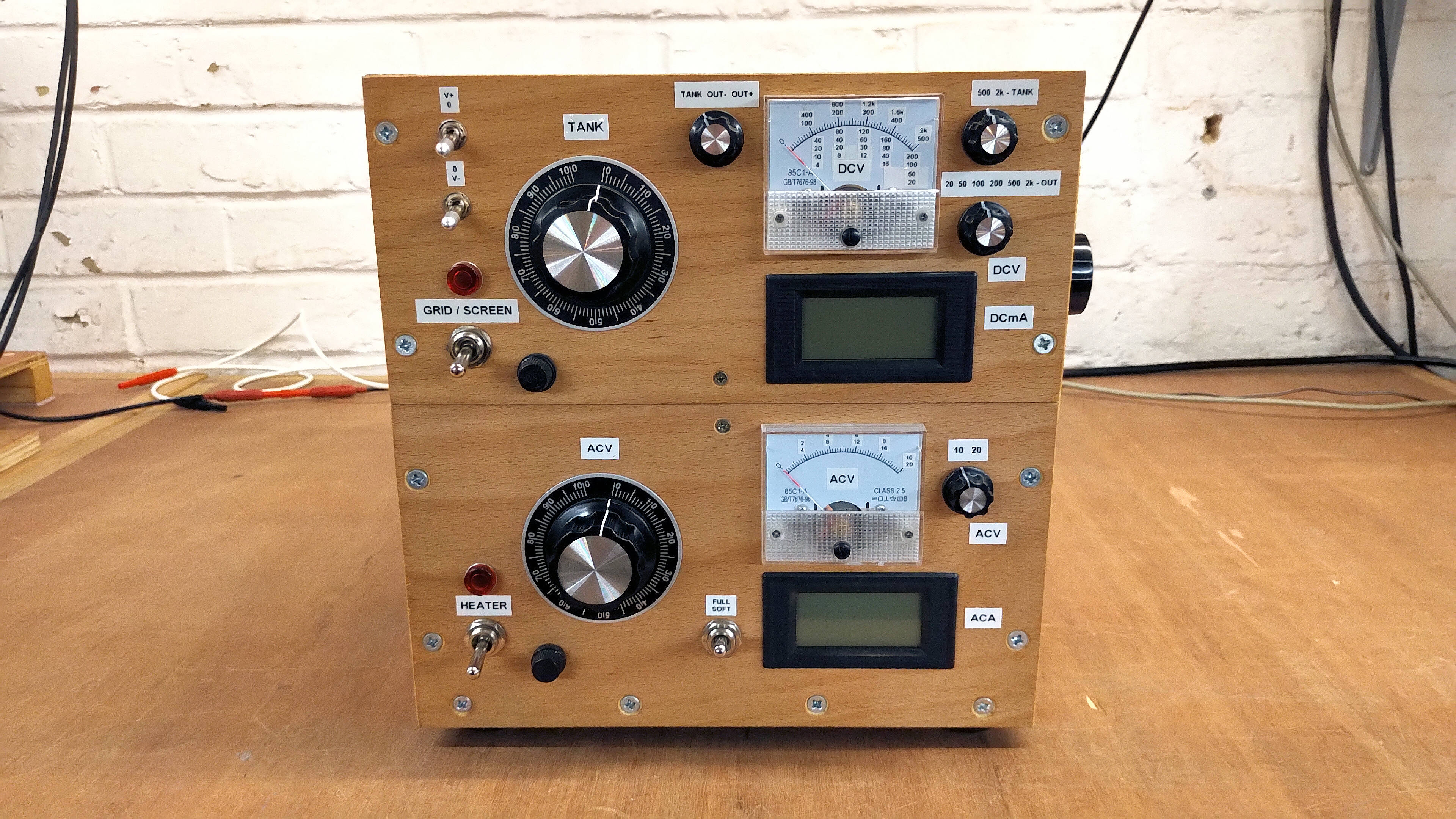
1. The heater, grid & screen supply is covered in this post, and provides the filament heater supply to the installed tube board with variable control up to a maximum 12.6V @ 25A, a finely controllable grid bias supply with wide operating characteristics between ±750V DC @ 200mA, or a finely controllable screen or auxiliary bias supply up to 1500V DC @200mA.
2. A high power 5kW plate supply using three 1.8kVA industrial microwave oven transformers, that can be configured in a variety of parallel and series arrangements to provide plate supplies including 2kV @ 2.3A, 4kV @ 0.8A, and up to 6kV @ 0.8A. A high voltage 40kV 6A bridge rectifier is incorporated into the design, along with a 12kV rapid discharge unit for safely discharging tank capacitors in the driven circuit. Also internally installed is a 4uF 6kV level shifter to increase the output up to 12kV @ 300mA and 15kV @ 150mA, which is suitable to drive medium power thyratron tubes, such as the 5C22 for pulse and impulse discharge experiments, as well as displacement of electric power experiments. I will be covering the design, construction and operation of this supply in a subsequent post.
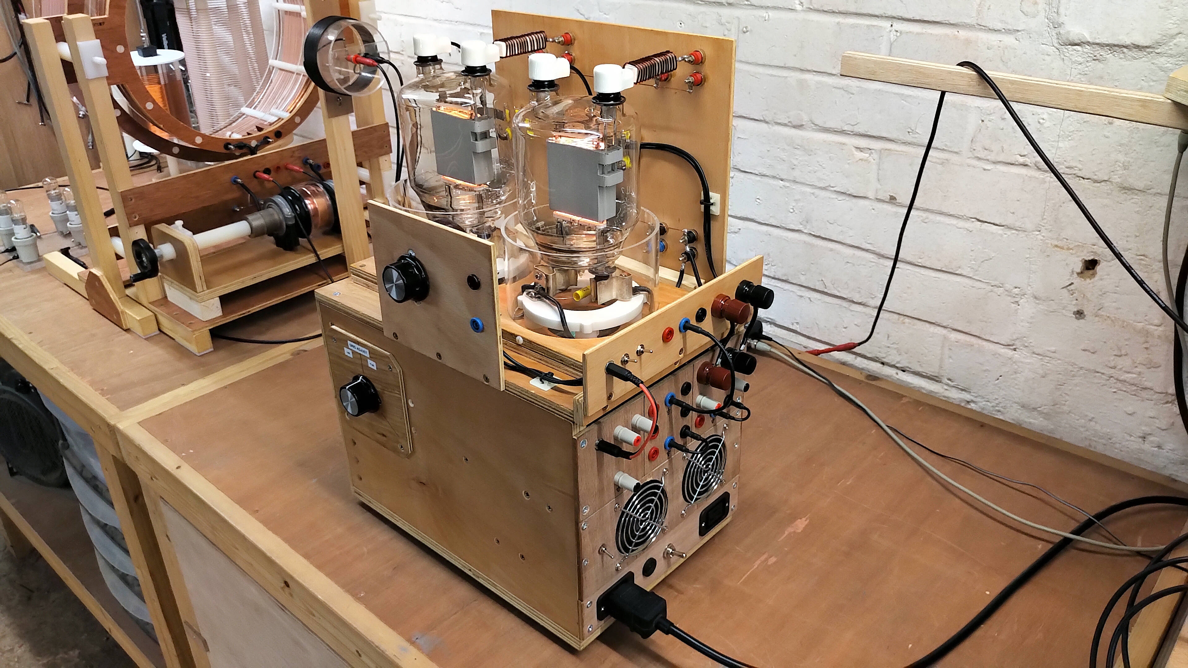
3. A dual 833C RF Power Triode tube board with graphite plates and with continuous axial cooling, driven at 4kV plate supply and with a total usable output power of ~ 3.0kW @ 2Mc, and the heater drive is 10V @ 20A AC for both tubes. The graphite plates of the C variant of the 833 tube improve significantly the top-end performance of this tube board by reducing plate to grid flash-over under high-power or poorly matched output conditions. Suitable for displacement and transference of electric power experiments, Tesla’s radiant energy and matter experiments, and including plasma, induction generator, and discharge phenomena.
4. A quad 811A RF Power Triode tube board with continuous axial cooling, driven at 1.2kV plate supply and with a useable output power of ~ 1kW @ 2Mc, and the heater drive is 6.3V @ 16A for all four tubes. This is a very versatile and flexible day-to-day workhorse with lower plate supply requirements, and facilitates a wide range of Tesla experiments as already demonstrated on my website using power up to 1kW.
5. A dual 4-400A RF Power Tetrode tube board with continuous axial cooling, and which is particularly good for high-fidelity musical Tesla coils, and linear amplifier type experiments where modulation and signal purity combined with good output power are required.
6. A dual 810C Power Triode tube board with graphite plates and continuous axial cooling, and which is particularly good for driving lower frequency Tesla coils in the hundreds of kilocycle frequency range, and with good power modulation and signal linearity.
The design, construction and operation of these tube boards will be covered in more detail in subsequent posts, and also operation of the complete tube power supply system as part of experiments yet to be presented on the website. So let us now get on with the tube power supply – heater, grid & screen unit with a video overview of its design, construction, and operation, and including driving a basic experiment using a single cylindrical Tesla coil with a single wire load. The video also demonstrates the use of both the dual 833C and quad 811A tube boards, here used as tuned plate class-C Armstrong oscillators, deriving linear feedback directly from the secondary coil oscillation, and primary circuit tuned to drive the cylindrical Tesla coil at the upper and lower parallel resonant frequencies.
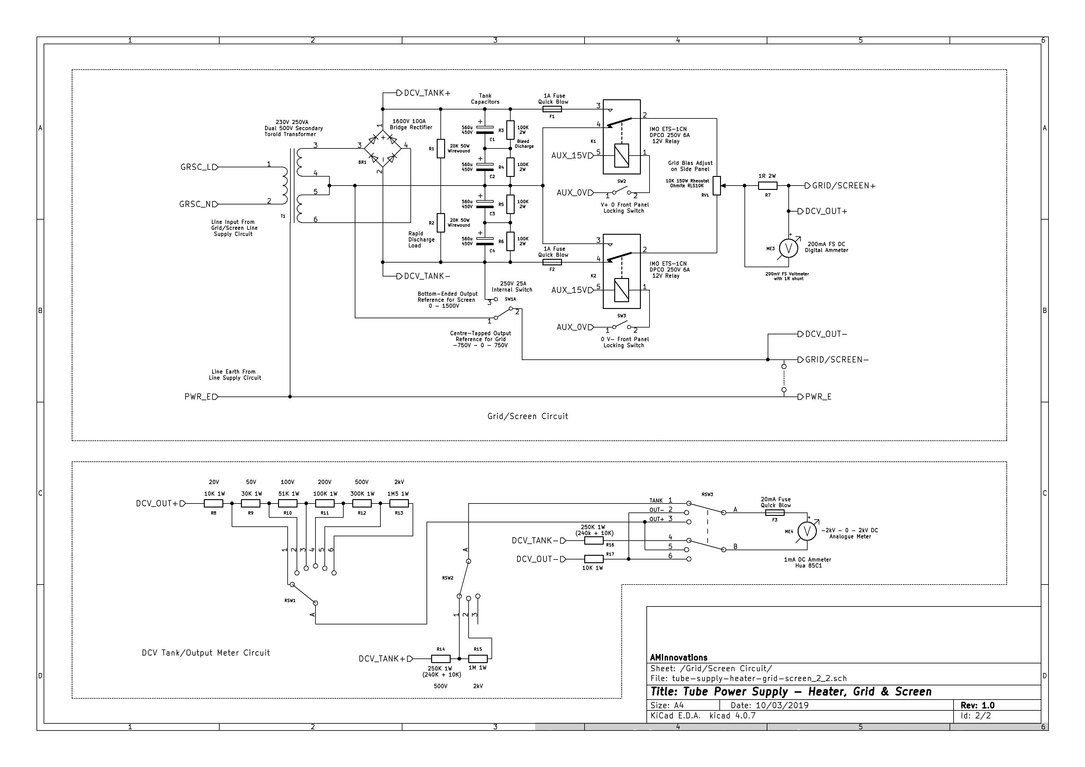
The circuit diagrams for the TPS-HGS are shown in Figures 2 below. To view the high-resolution versions click here on Fig 1.1 or Fig1.2.
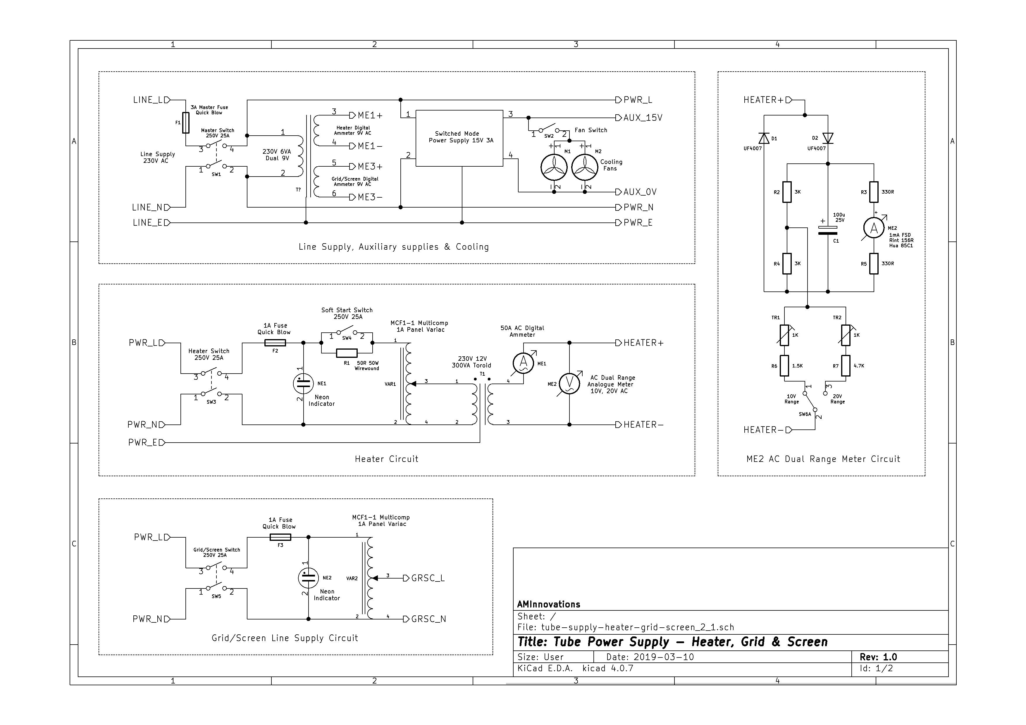


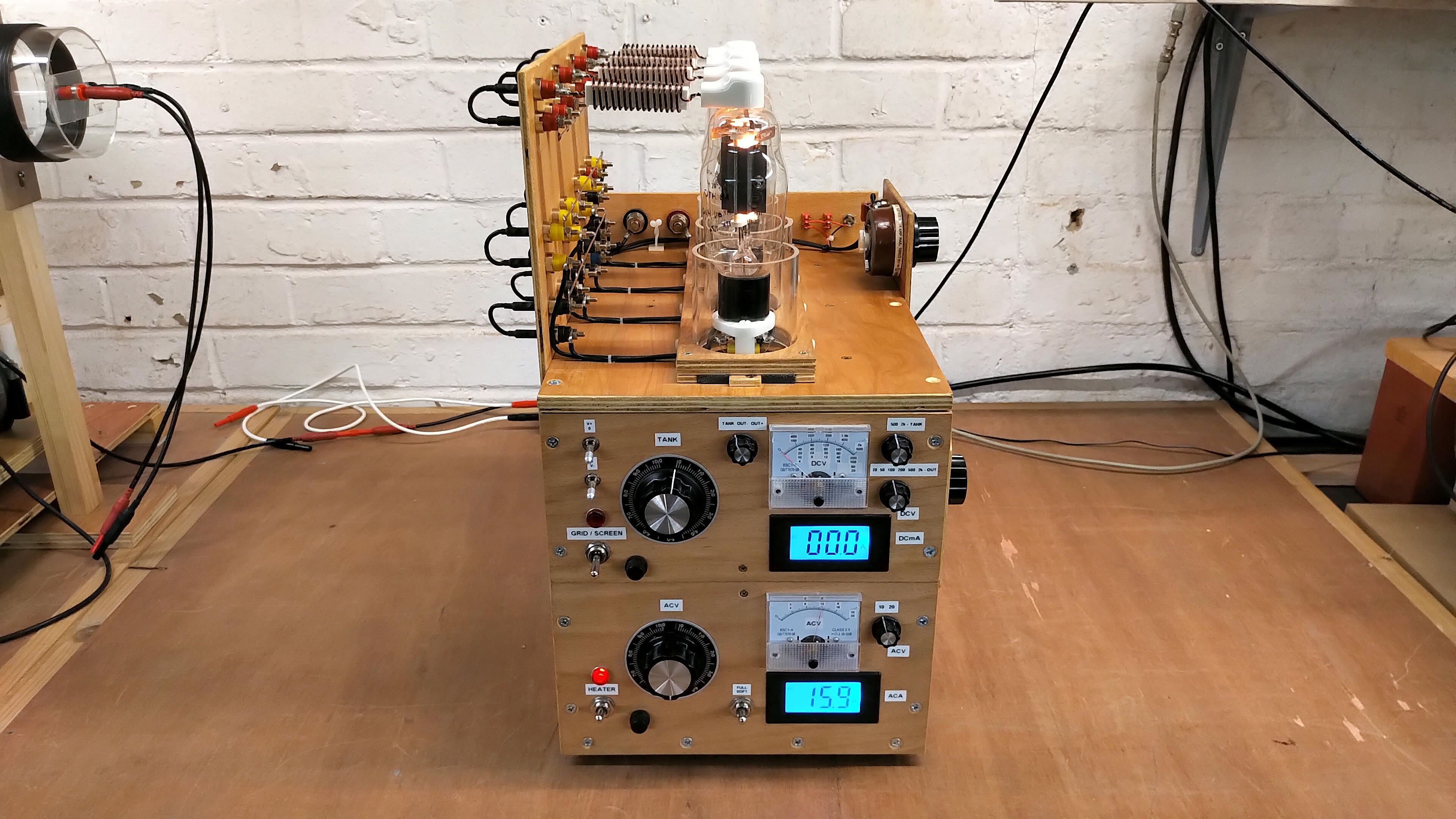
The principle of operation for the heater supply unit is as follows. This supply provides a high current low voltage output to drive the filaments in the tube board when connected in series or parallel arrangements. The internal resistance of the vacuum tube filaments determine the supply requirements without any additional regulation at the supply end. To this effect a 12V 300VA transformer can be adjusted using a variac to correctly bias the requirements of the tube board both in voltage and current. The power rating of the transformer was selected to adequately cover the various tube boards being used, and is capable of a maximum of 12.6V @ 25A. Open circuit the supply provides 15.9V which reduces with increased load, and to the correct filament voltage and current when adjusted by the variac.
A soft-start switch is incorporated to switch a resistive load 50Ω 50W into the primary circuit of the transformer, which reduces the potential across the primary, and hence reduces the secondary output. When vacuum tubes are cold the filament resistance is generally much lower than when in normal operation, and the initial in-rush of current when power is first applied to the filament circuit can easily exceed the maximum safe ratings, which can lead to significantly reduced filament lifetime and premature failure of the filaments in one or more tubes. The ac voltage and current supplied by the heater supply is monitored using an analogue true rms circuit through a DC 1mA ammeter, and a digital 50A AC ammeter based on the potential difference across a 75mΩ series resistance in the output circuit.
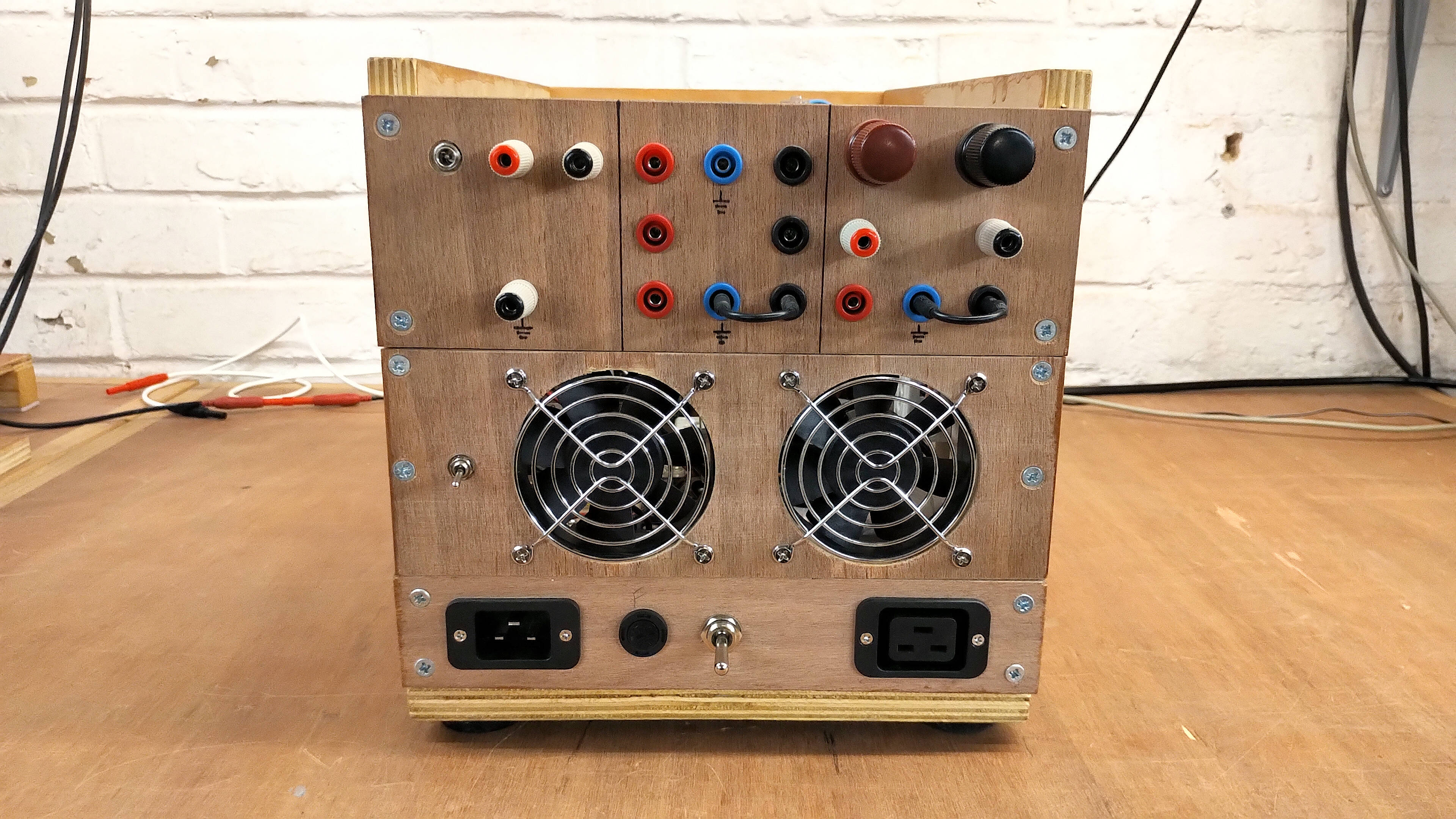
The digital ammeter is most effective for setting accurate bias current prior to RF circuit operation. The outputs of the heater circuit are arranged flexibly on the back panel to allow rapid and configurable connection to the tube boards, and including the ability to float the filament supply above the line supply earth. Disconnecting the heater supply from the line earth allows the vacuum tube to be cathode switched, modulated, or “pulsed”, and for the tube board to be referenced to a different “ground” e.g. a dedicated RF ground, or plate supply with high voltage biased negative, (useful for extreme high-voltage thyratron supplies).
The principle of operation for the grid/screen bias unit is as follows. This supply provides a stable unregulated output bias based on the voltage accumulated in a tank circuit, and which can be finely controlled by a high power potential divider to the output. A high-voltage transformer with dual secondary coils rated at 500V each with a total power output of 250VA is adjusted using a variac on its primary circuit. This gives a variable output voltage of ±500VRMS @ 200mA when negative reference is at the centre tap, or 1000VRMS @ 200mA when negative reference is at the bottom-end of the lower secondary coil. The output of the high-voltage transformer is bridge rectified and then accumulated on a tank capacitor circuit consisting of 4 x 560µF 450V capacitors in series. Bleed resistors and a high-power parallel load resistance are provided for rapid discharge of the tank when switched off. The tank is intended to provide a stable DC supply with very low output ripple up to 200mA for grid and screen bias purposes.
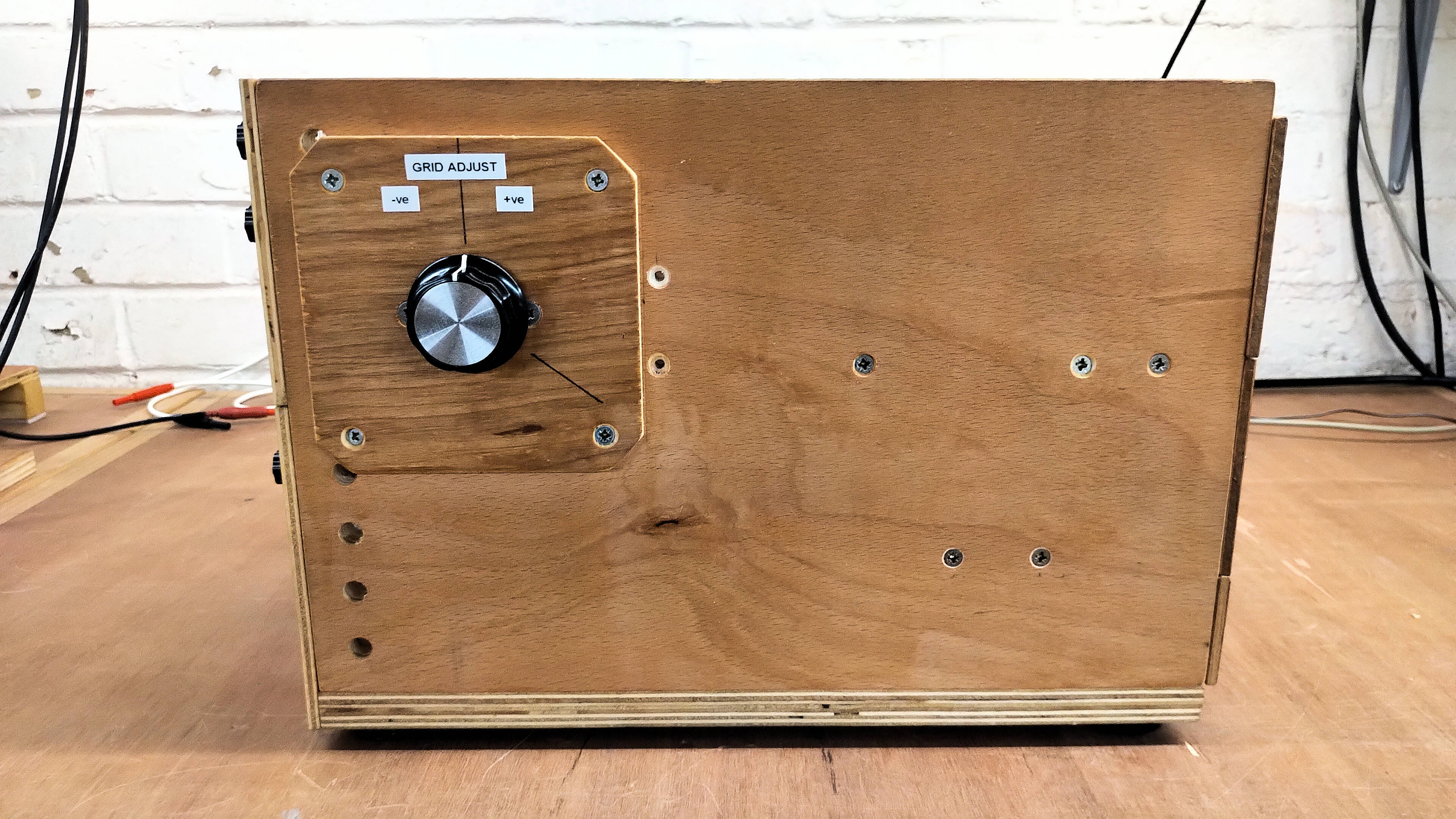
To facilitate very fine adjustments in grid bias, which is often very necessary to establish the best operating point for a tube amplifier or oscillator, the output of the tank circuit is fed through a 150W 10kΩ rheostat, which provides continuous linear adjustment of the output across the entire range of the tank voltage. This allows for initial setup of the tube board prior to application of the plate supply, and then variable bias tuning during operation of the experiment. As the bias output is unregulated changes to the experimental conditions will effect required changes to the grid bias and this can be safely and readily applied through the grid bias rheostat. The final result is a very flexible supply that can accommodate a wide range of different tubes and operating conditions. Rapid adjustment of these parameters in a research and development context greatly reduces experimental setup and adjustment time, and facilitates easy tuning to find the most optimum point of operation.
The rheostat fine control is fed from the tank capacitors via two changeover high-voltage relays that switch the output between the upper and lower secondary coils, or across both coils. This allows the output range to be more precisely and safely controlled by selecting just a negative output range, a positive output range, or the entire tank range. This has benefit for example when biasing a tube board in grounded cathode for linear amplifier application. Here the grid bias for a class C linear amplifier is usually in the negative range, so to minimise power dissipation in the grid adjust rheostat, and to ensure that the bias cannot drift into positive voltage with higher risk of tube damage, the output relays are configured to connect only the negative section of the tank circuit across the grid adjust rheostat and hence to the output.
Measurement of DC tank voltage, and output bias voltage is accomplished by a switched series resistance which scales the current into an ammeter up to 1mA. For greater accuracy and scale size the analogue meter is switched either to measure a negative bias potential, or a positive bias potential, by switched reversal of the measurement current through the meter. This series resistance method gives a very good dynamic range of measurement with ranges between 20V DC FSD, and 2kV DC FSD. The process of operating the grid/screen supply requires that the tank voltage first be set to a value higher than is required for the output bias, and then the output bias set through the fine control of the grid adjust.
The switching between these measurements is quickly and easily facilitated by the rotary controls on the front panel of the instrument. The rotary switches are plastic spindle types, which also provide excellent isolation during operation from internal high voltage. It should also be noted that the switched series resistance also has part of that resistance chain in the negative terminal of the output e.g. R14, R15, R16, R17. These resistors prevent current surges between the various output circuits during switching of the measurement ranges, and also inadvertent changes to the setting of the tank output relays when the tank circuit is not discharged. This is particularly important at high tank voltages where switching could otherwise result in large surge currents and destruction of the relays, and other switching components. I discovered this one during inital supply tests, and needed to change both relays and a rotary switch that had burned and fused contacts from a surge at maximum tank setting of 1500V!
Measurement of DC output current is by digital ammeter with 200mA FS. The digital meter is a 200mV FS DC meter which has a 1Ω 2W shunt resistor at the output of the grid adjust rheostat. As for the heater supply, the digital readout facilitates accurate bias adjustment and setup prior to operation of the tube board at RF frequencies. Overall the two supply units are simple in design and construction, and compact and cost effective in materials and components, but lead to a very wide range of operating characteristics, which can be quickly and easily adjusted by a skilled operator during the experimental process.
Figures 2 below show the complete unit with both the dual 833C and quad 811A tube boards installed. The pictures illustrate the compact yet powerful design, and particularly the space saving footprint on the bench. When combined with the 5kW high-power plate supply, the two together form a very versatile and robust tube power supply suitable for a very wide range of Tesla and high-voltage research experiments including, displacement and transference of electric power, Telluric transmission of power, radiant energy and matter, modulated and high-fidelity waveforms, and plasma and discharge phenomena. The same plate supply combined with a specialised 5C22 thyratron board and pulse trigger unit is well suited to displacement of electric power, pulse, impulse, and unidirectional discharge phenomena.
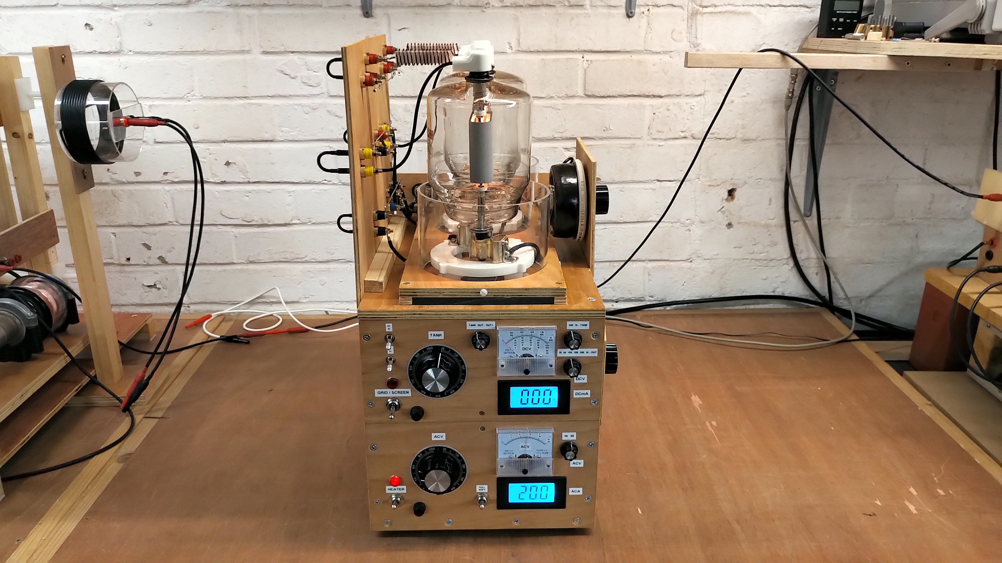
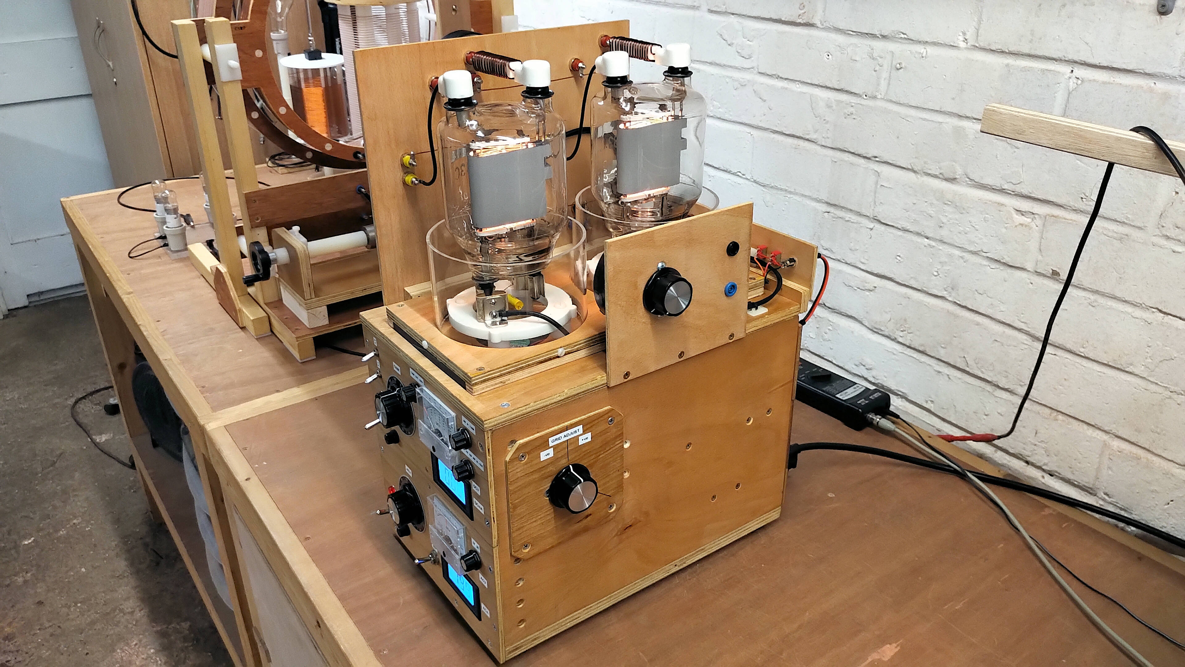
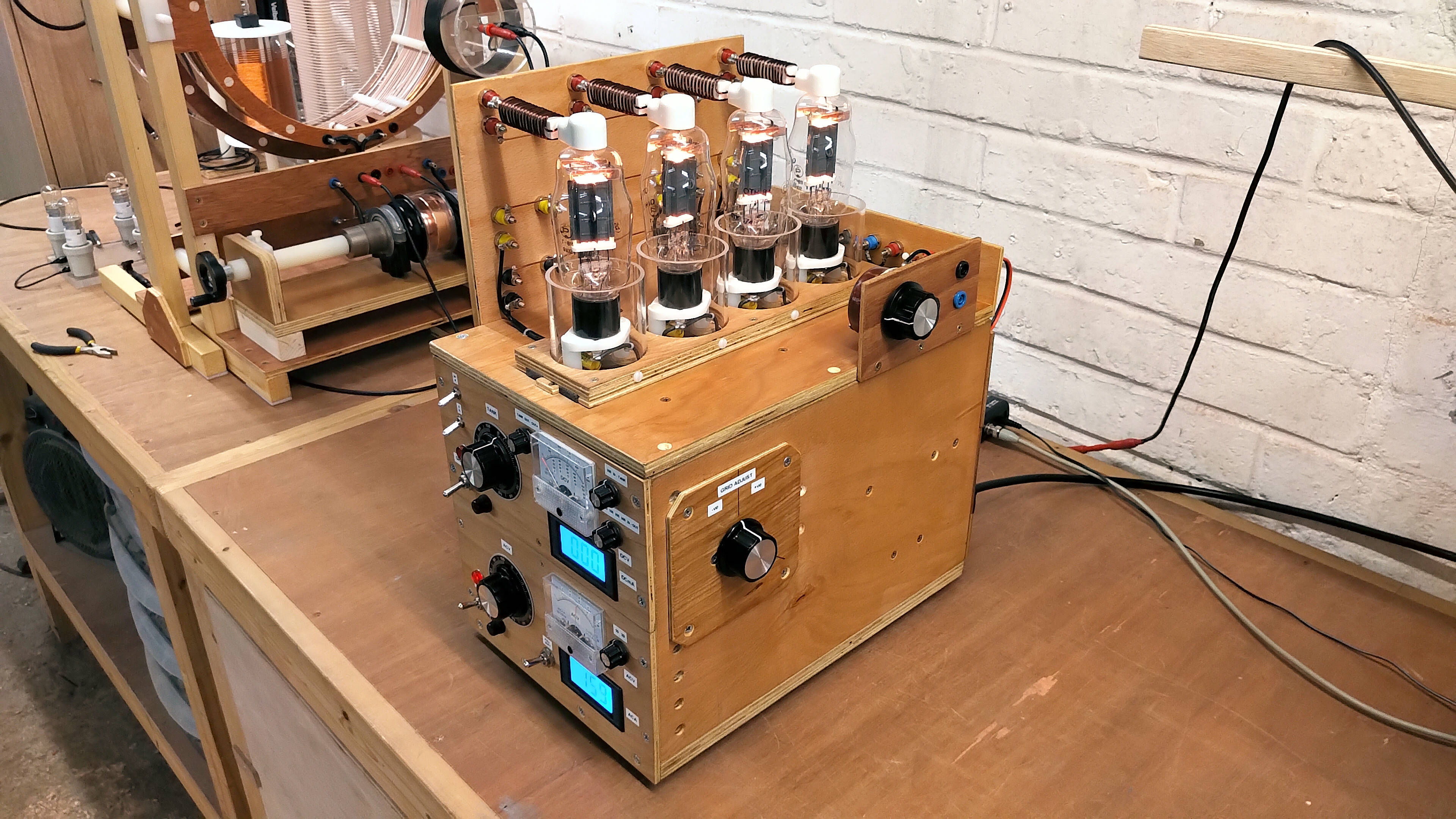
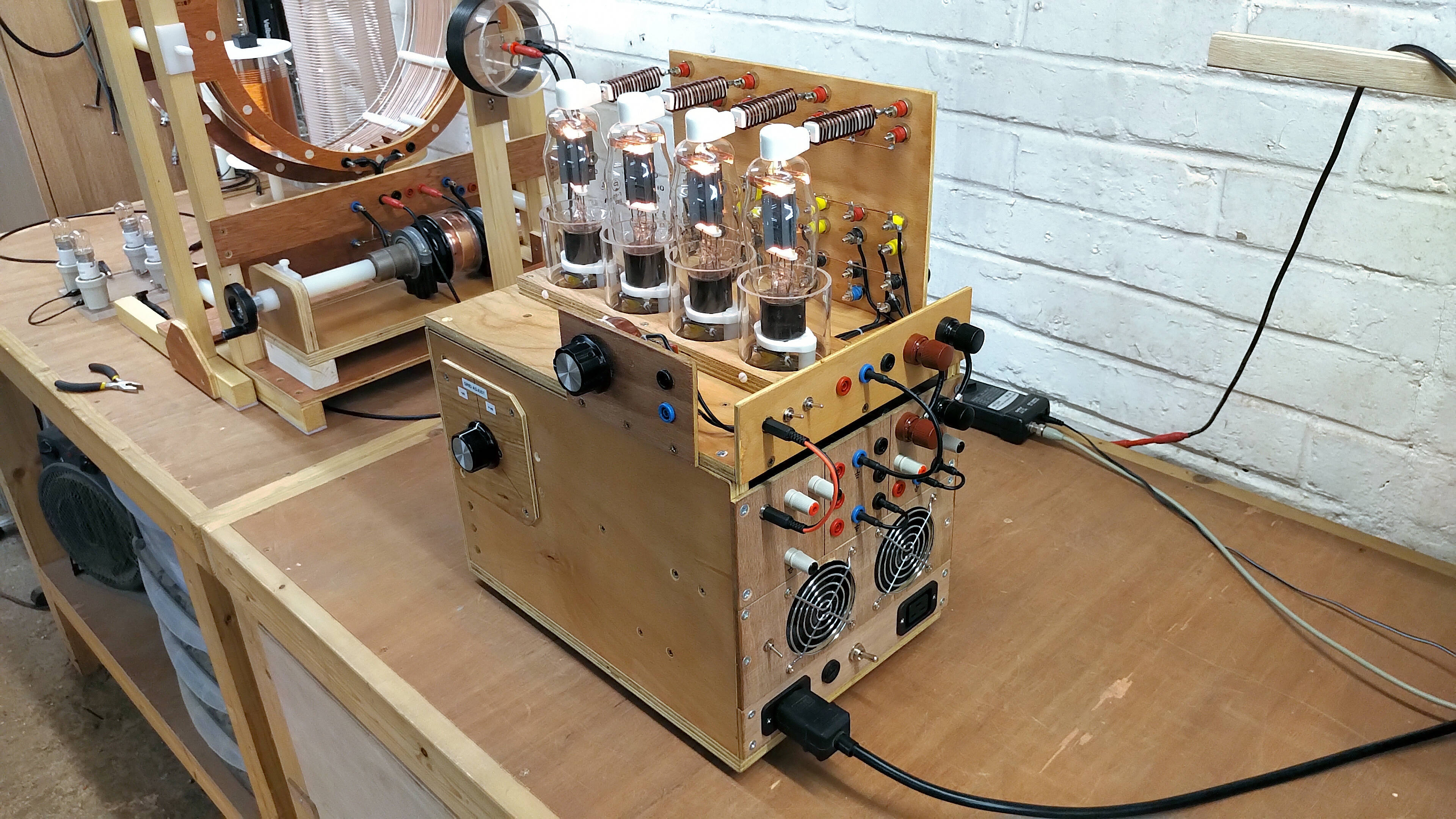


Figures 3 below show the internal layout and construction of the complete heater, grid & screen tube supply. The entire unit is housed in an oil varnished plywood housing, with consideration for cooling, correct line earthing of the appropriate components, internal safety of the high-voltage components and regions, and the external safety of the operator with the various controls when adjusted during the experimental process. As discussed on the video, the choice of a wooden enclosure faciltates easy fabrication and construction, with reasonable thermal properties when fan-cooled, and reasonable external isolation from high-voltage components and regions.
The wooden enclosure does not facilitate grounding and earth connection of certain components, which requires more considered wiring and interconnection of line earth around the internal layout. The wooden enclosure provides no EMI protection either externally to other objects in the facinity, or internally from electric and dielectric fields of induction around the experiment. In a research and development environment in an industrial and isolated setting this is considered acceptable given the often short operation time periods, and minimum interference to surrounding infrastructure.
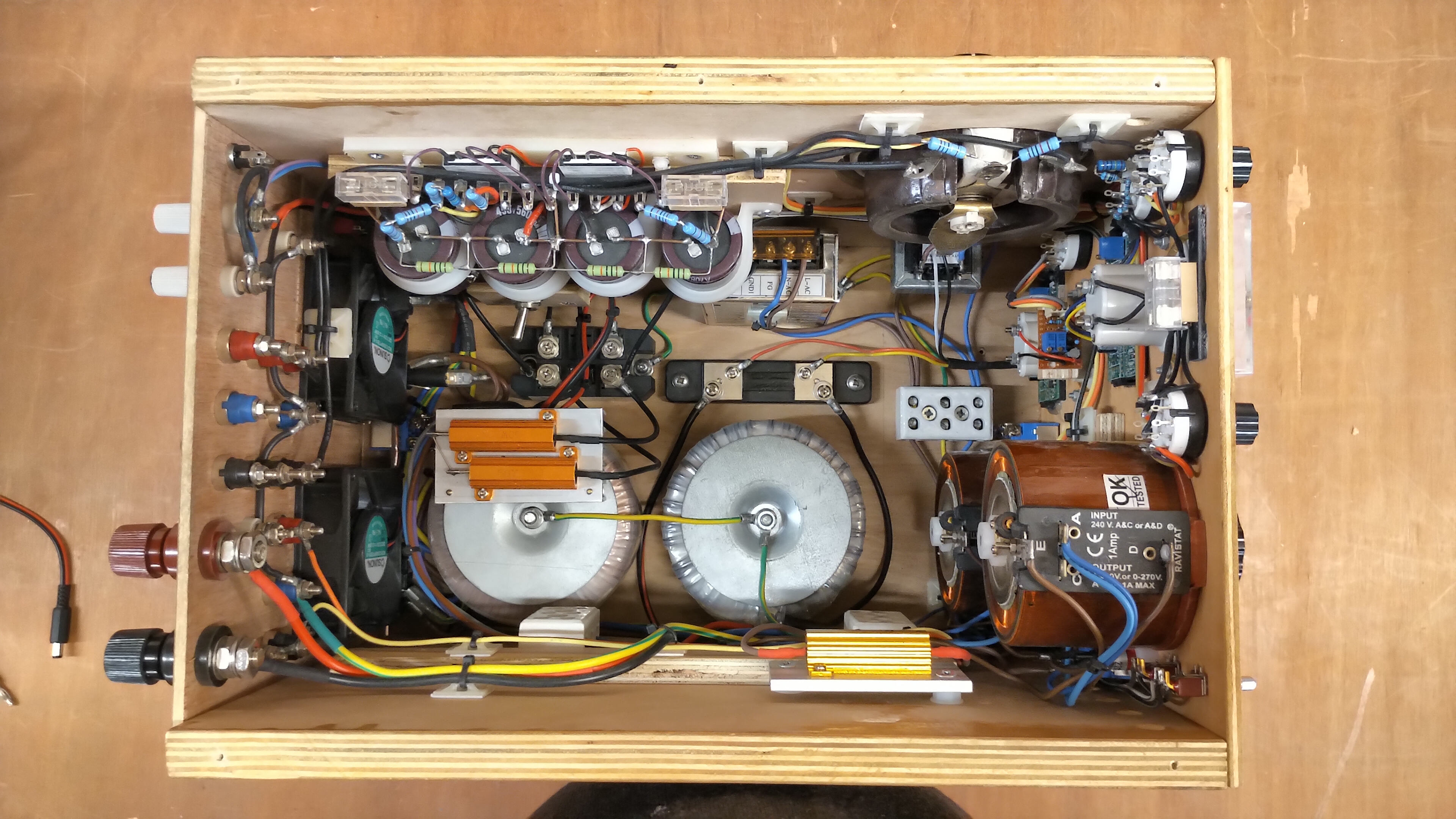
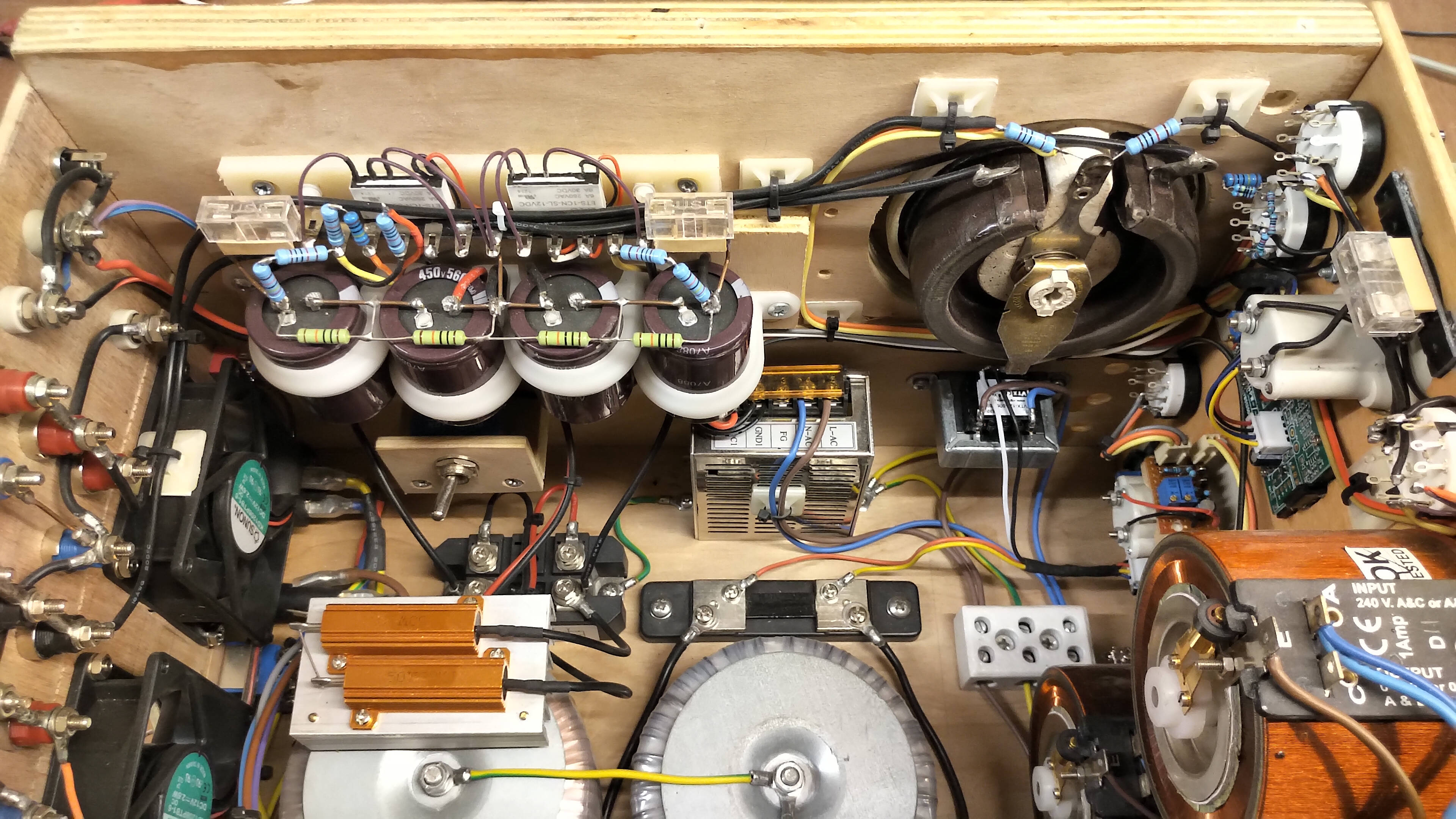
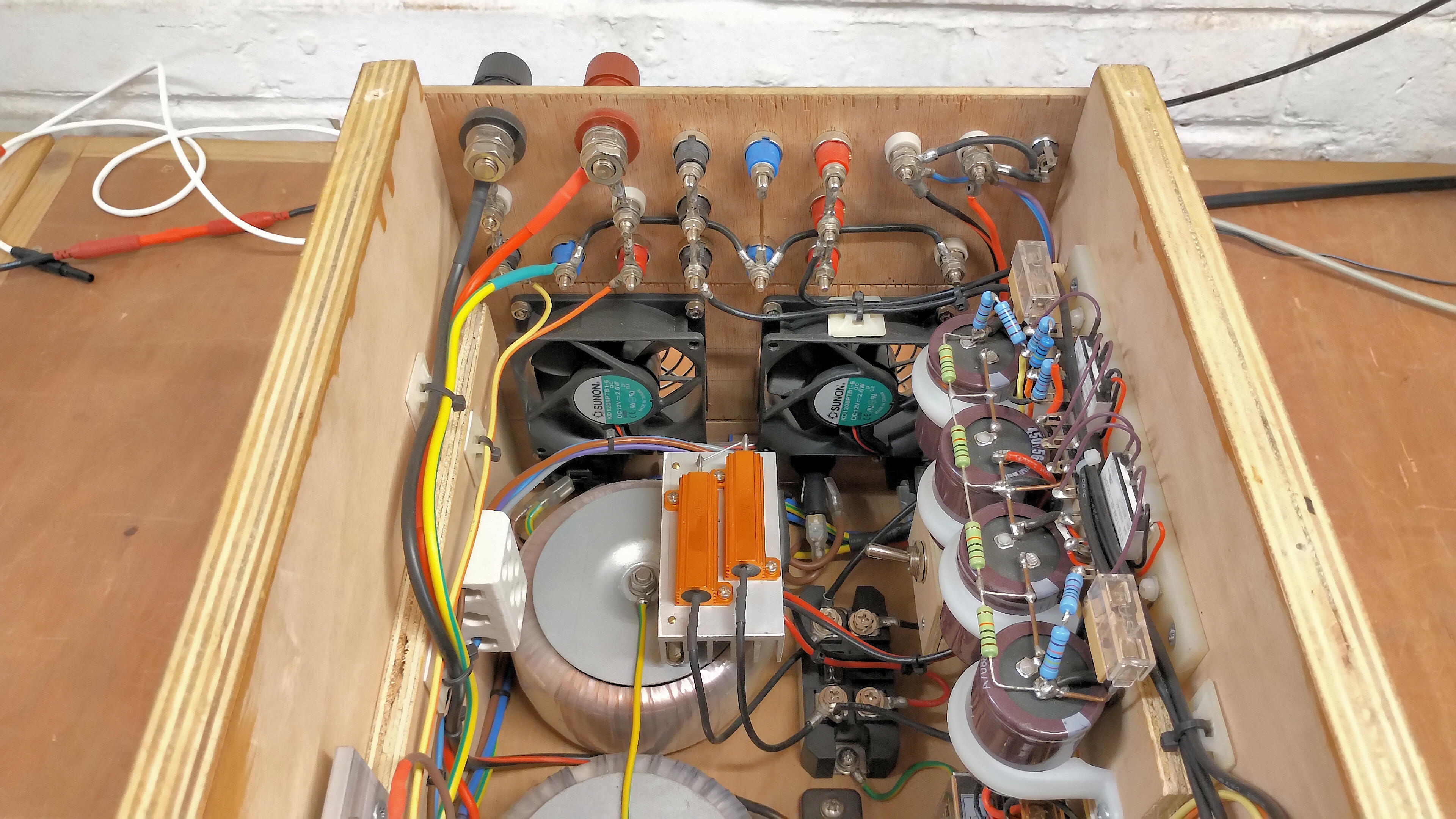
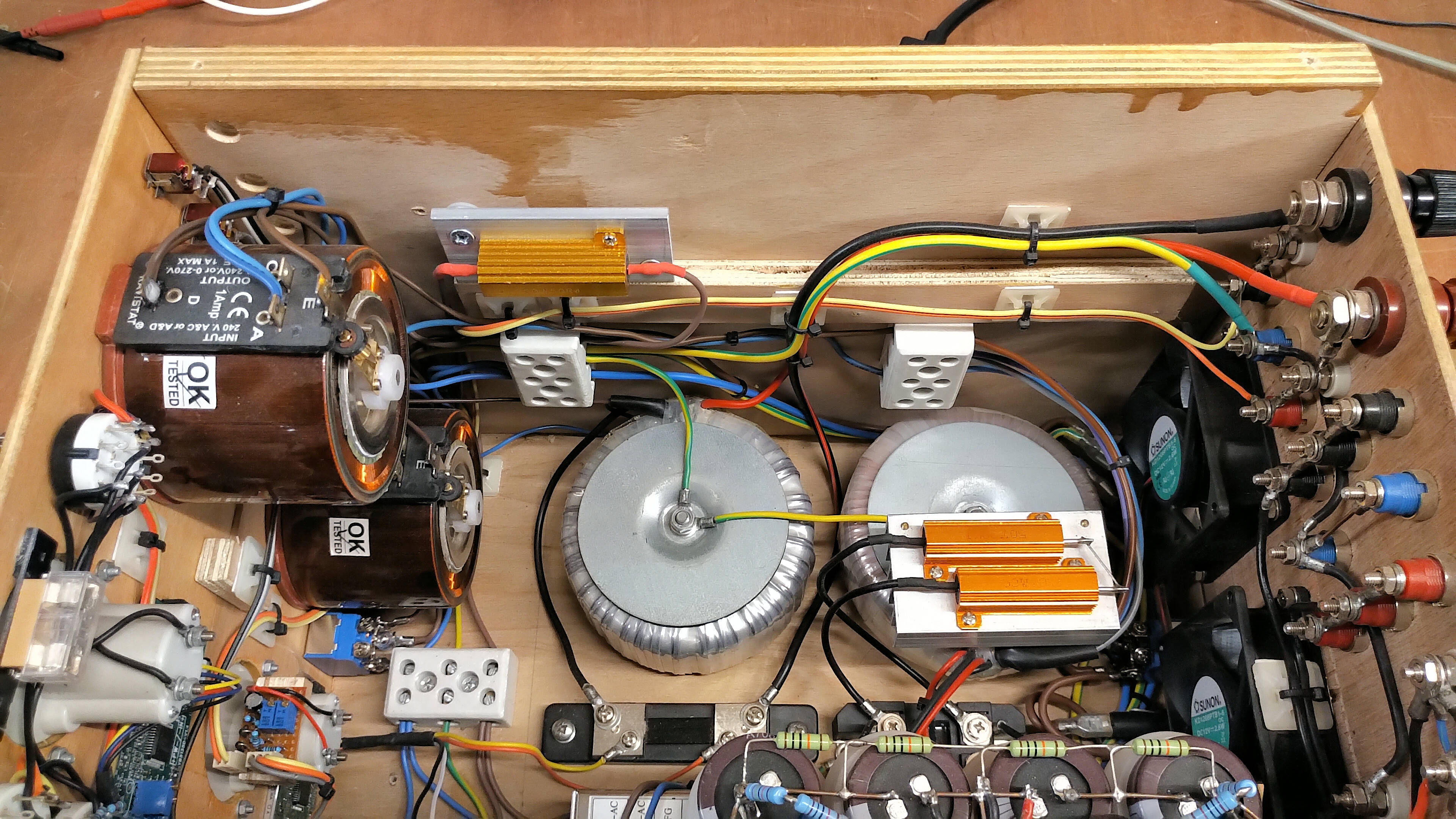
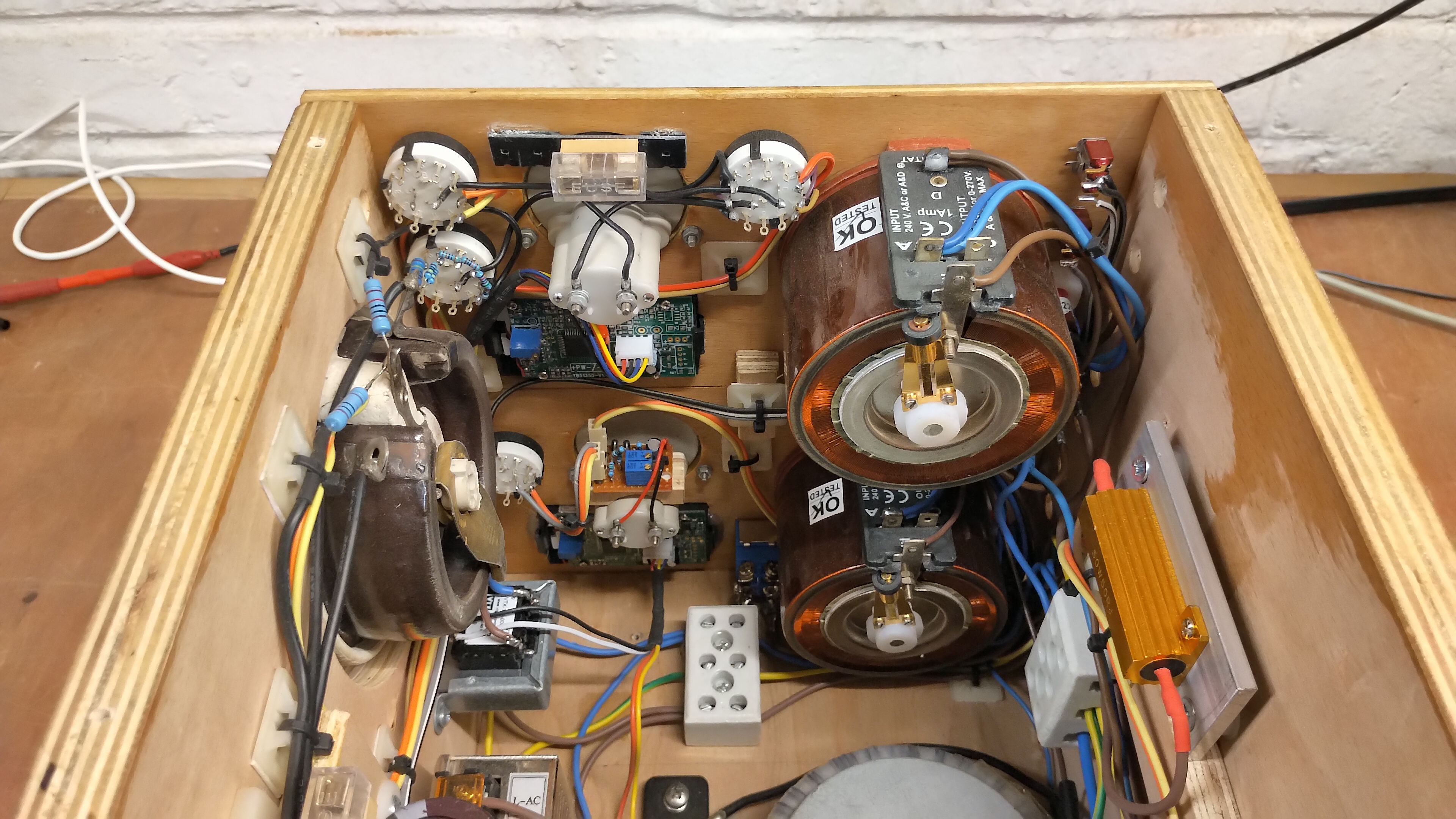
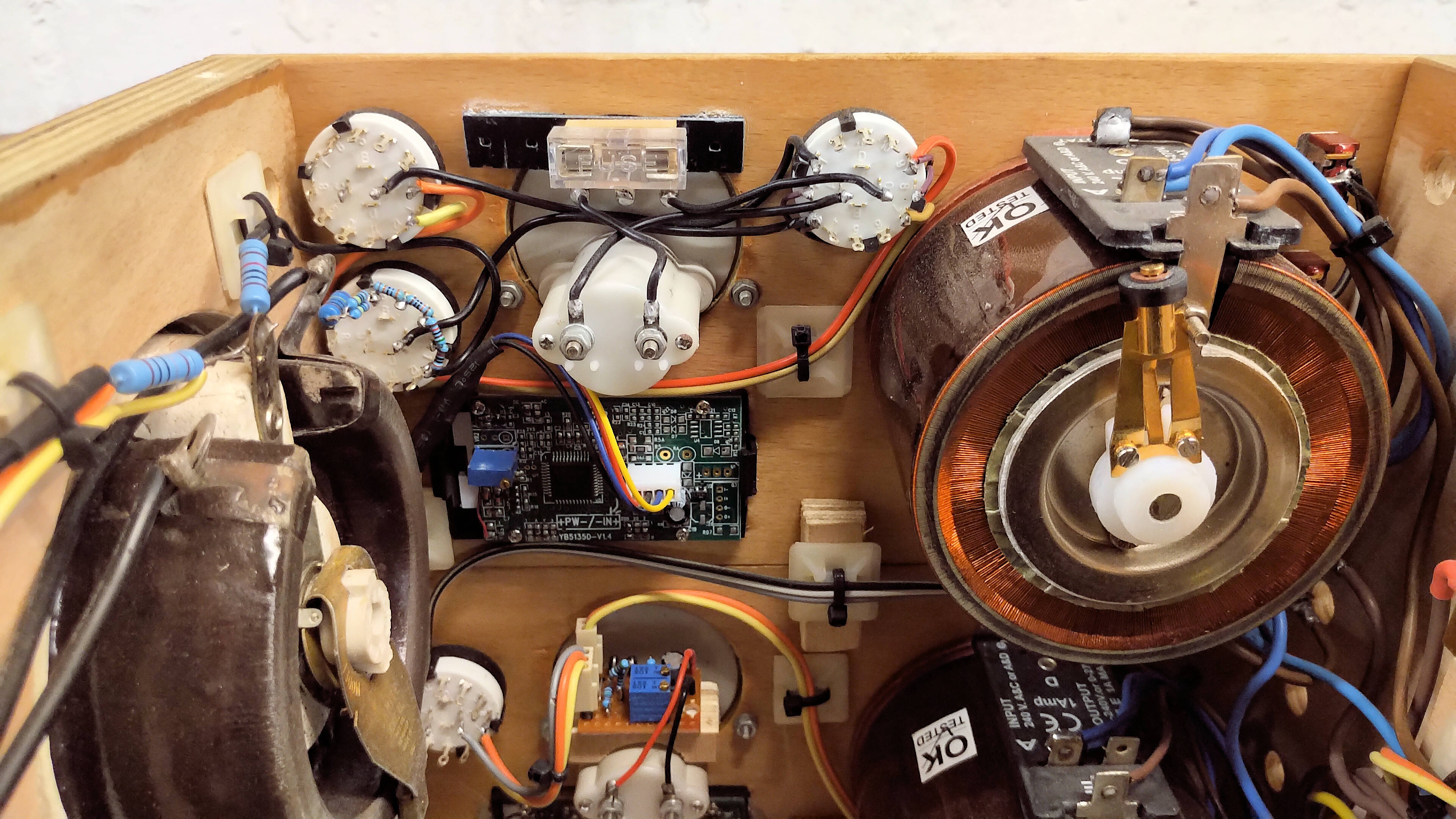
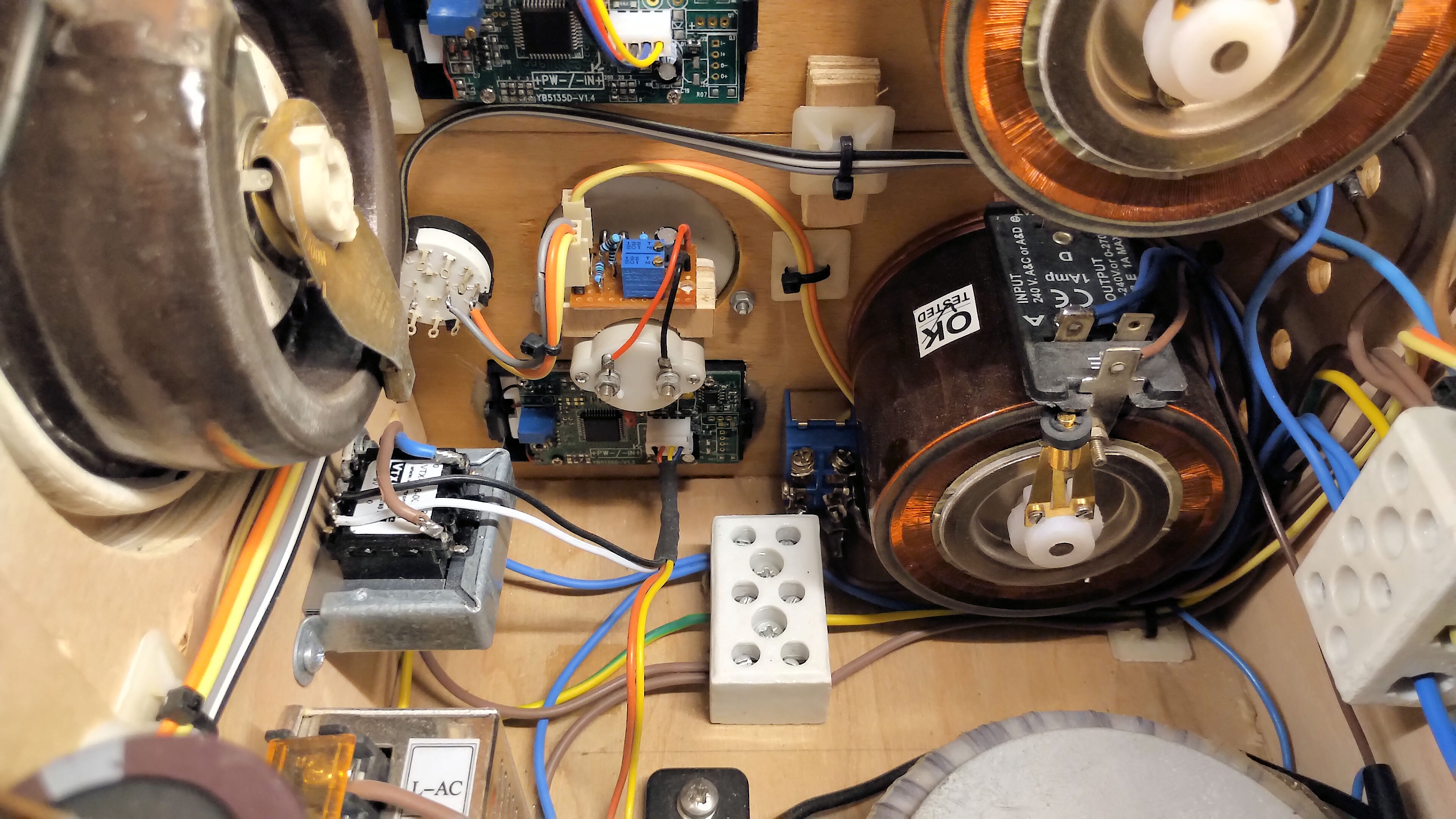
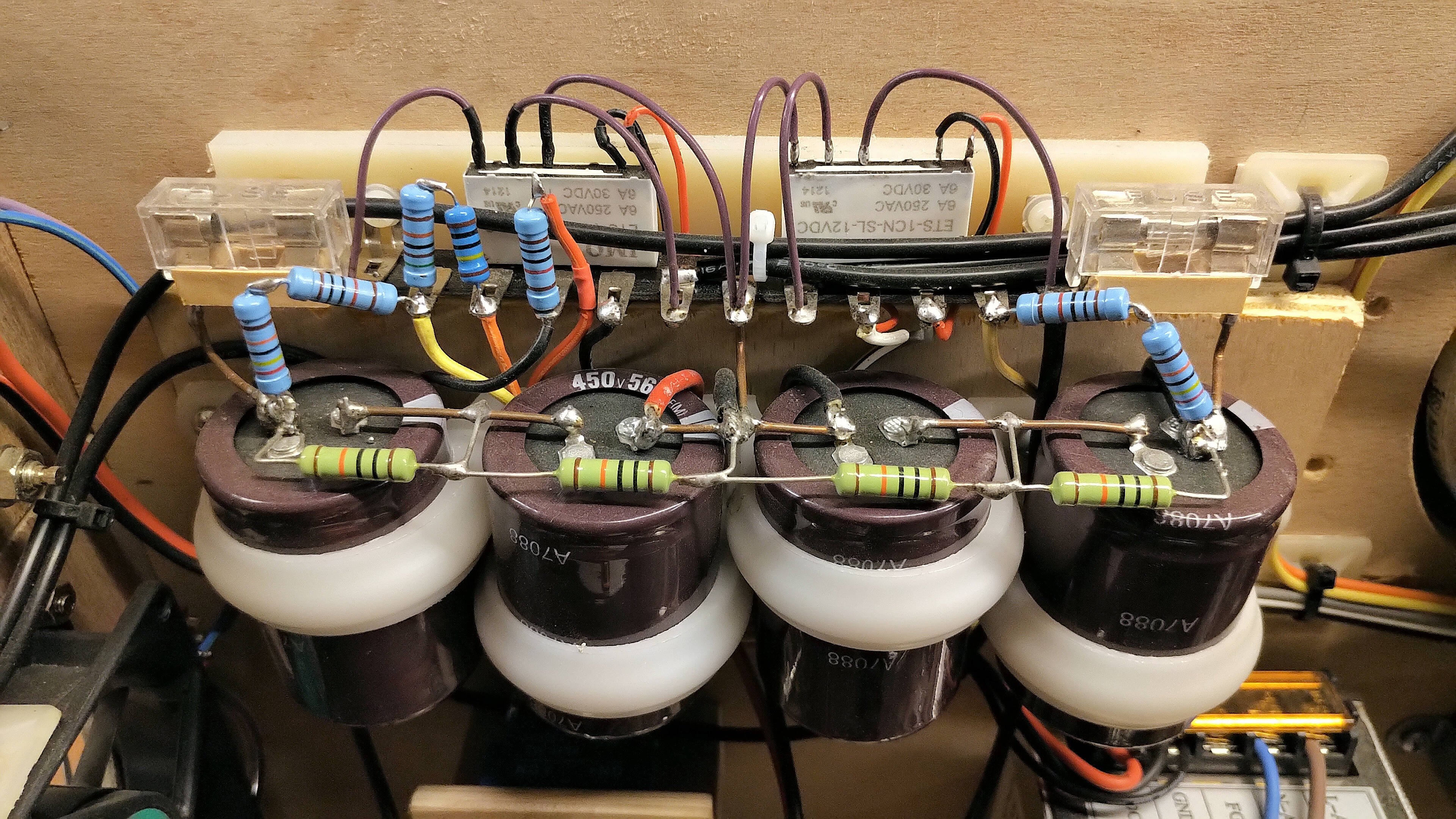
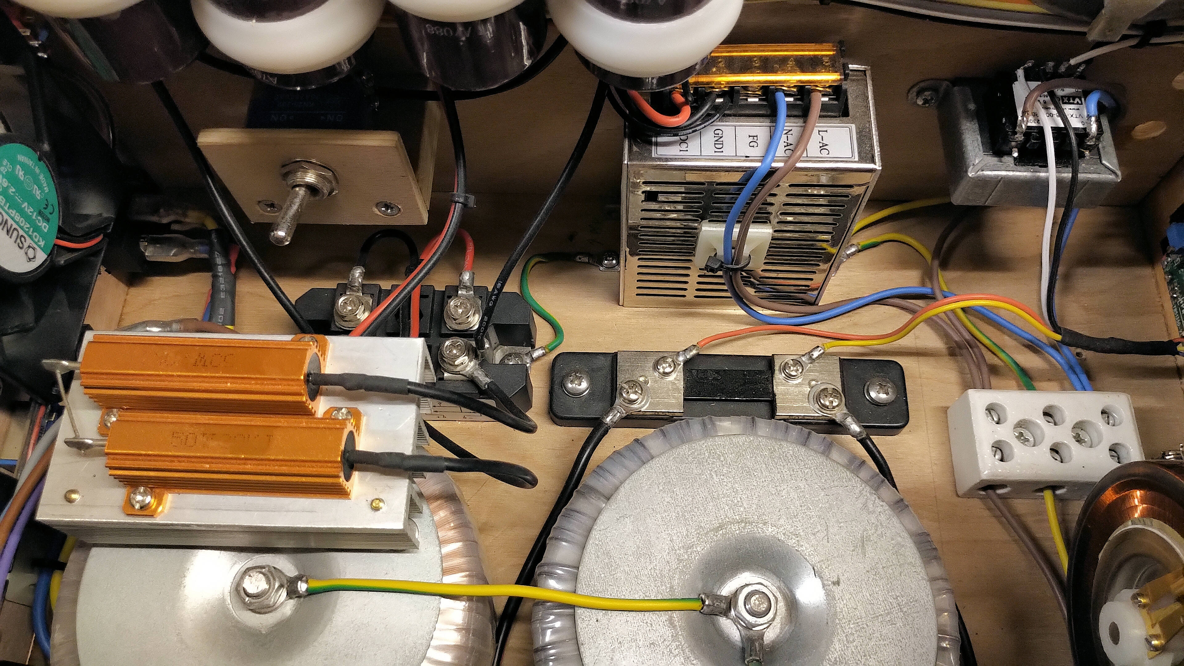


It can be seen from figures 3 that the overall layout and construction is relatively straightforward. Care with proper positioning and wiring of the high voltage components is very important, particularly in spacing of contacts, the wire type used to connect the high voltage components, and isolation from the user controls on the front-panel. Otherwise a flexible design is possible from a simple circuit, is easy to diagnose and fix if and when a problem occurs, and facilitates a very wide range of experimental conditions that can be adapted, adjusted, and tuned quickly in a research and development prototype setting.
The next parts in this tube power supply series will cover the plate supply, and the individual tube board designs and circuit configurations.
Click here to continue to the next part, looking at Tube Power Supply – High Voltage & Plate.
1. A & P Electronic Media, AMInnovations by Adrian Marsh, 2019, EMediaPress
2. Dollard, E. and Energetic Forum Members, Energetic Forum, 2008 onwards.